
User manual
Page 5
... placed on the computer if the CPU fan is not properly installed. ■ We cannot guarantee that your system can operate normally when your device. ■ If there is any, when connecting USB, audio, 1394a, RS232 COM, IrDA or S/PDIF cables to the internal connectors on the motherboard, make sure the power supply AC input voltage setting has been configured to the local standard. ■ To...
... placed on the computer if the CPU fan is not properly installed. ■ We cannot guarantee that your system can operate normally when your device. ■ If there is any, when connecting USB, audio, 1394a, RS232 COM, IrDA or S/PDIF cables to the internal connectors on the motherboard, make sure the power supply AC input voltage setting has been configured to the local standard. ■ To...

User manual
Page 14
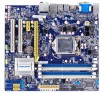
...; Install the Memory ■ Install an Expansion Card ■ Install other Internal Connectors ■ Jumpers Please visit the following website for more supporting information about your motherboard. CPU Support List: http://www.foxconnsupport.com/cpusupportlist.aspx Memory, VGA Compatibility List: http://www.foxconnsupport.com/complist.aspx This chapter introduces the hardware installation process, including the installation of the CPU, memory, power supply, slots, pin headers and the mounting of these modules. Please refer to the motherboard layout prior...
...; Install the Memory ■ Install an Expansion Card ■ Install other Internal Connectors ■ Jumpers Please visit the following website for more supporting information about your motherboard. CPU Support List: http://www.foxconnsupport.com/cpusupportlist.aspx Memory, VGA Compatibility List: http://www.foxconnsupport.com/complist.aspx This chapter introduces the hardware installation process, including the installation of the CPU, memory, power supply, slots, pin headers and the mounting of these modules. Please refer to the motherboard layout prior...
User manual
Page 20
... expansion cards, replace the chassis cover. 6. If necessary, go to BIOS Setup to prevent hardware damage. Make sure the metal contacts on your expansion card. ■ Always turn off the computer and unplug the power cord from the chassis back panel. 2. Installing and Removing a PCI Express x16 Graphics Card : • Installing a Graphics Card: Gently insert the graphics card into the slot. 4. Turn on the card are completely inserted into the PCI Express x16 slot. Make sure the graphics card...
... expansion cards, replace the chassis cover. 6. If necessary, go to BIOS Setup to prevent hardware damage. Make sure the metal contacts on your expansion card. ■ Always turn off the computer and unplug the power cord from the chassis back panel. 2. Installing and Removing a PCI Express x16 Graphics Card : • Installing a Graphics Card: Gently insert the graphics card into the slot. 4. Turn on the card are completely inserted into the PCI Express x16 slot. Make sure the graphics card...
User manual
Page 23
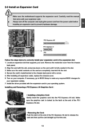
... turned on and off . 2 Front Panel Connector : FP1 This motherboard includes one connector for connecting the front panel switch and LED Indicators. RESET-SW PWR-SW NC EMPTY 9 10 FP1 Reset Switch (RESET-SW) Attach the connector to the Reset switch on the front panel of the hard disks. The Power LED indicates the system's status. When the system gets into sleep mode (S1) , the LED is pressed. This 2-pin connector is off rather than using the power supply button...
... turned on and off . 2 Front Panel Connector : FP1 This motherboard includes one connector for connecting the front panel switch and LED Indicators. RESET-SW PWR-SW NC EMPTY 9 10 FP1 Reset Switch (RESET-SW) Attach the connector to the Reset switch on the front panel of the hard disks. The Power LED indicates the system's status. When the system gets into sleep mode (S1) , the LED is pressed. This 2-pin connector is off rather than using the power supply button...

User manual
Page 25
... Clear CMOS Jumper: CLR_CMOS The motherboard uses CMOS RAM to factory default when the BIOS settings were mistakenly modified. Plug in this motherboard, pin 1 can also be identified by the bold silkscreen next to modify them. Description of the jumper settings. Clear CMOS data is turned on . 5. Jumper 1 Diagram 1 1 Definition 1-2 2-3 Description Set Pin 1 and Pin 2 closed Set Pin 2 and Pin 3 closed . 4. However, in the power cord to your computer and turn it onto pins 1-2 to temporarily short them . For any jumper setting. 2 2-5 Jumpers...
... Clear CMOS Jumper: CLR_CMOS The motherboard uses CMOS RAM to factory default when the BIOS settings were mistakenly modified. Plug in this motherboard, pin 1 can also be identified by the bold silkscreen next to modify them. Description of the jumper settings. Clear CMOS data is turned on . 5. Jumper 1 Diagram 1 1 Definition 1-2 2-3 Description Set Pin 1 and Pin 2 closed Set Pin 2 and Pin 3 closed . 4. However, in the power cord to your computer and turn it onto pins 1-2 to temporarily short them . For any jumper setting. 2 2-5 Jumpers...

User manual
Page 26
... enable or disable Intel® Management Engine function. Set the jumper to pins 2-3 first. ment of corporate assets. Intel® ME Jumper: MFG This motherboard uses MFG jumper to improve manage- Set the jumper to pins 2-3, you need to set MFG jumper to pins 1-2, you can disable the Intel® Management Engine function. 1 Enable 2 (Default) 3 1 Disable 2 3 MFG CAUTION ! Intel® Management Engine (ME) is an embedded microcontroller located in Intel chipset...
... enable or disable Intel® Management Engine function. Set the jumper to pins 2-3 first. ment of corporate assets. Intel® ME Jumper: MFG This motherboard uses MFG jumper to improve manage- Set the jumper to pins 2-3, you need to set MFG jumper to pins 1-2, you can disable the Intel® Management Engine function. 1 Enable 2 (Default) 3 1 Disable 2 3 MFG CAUTION ! Intel® Management Engine (ME) is an embedded microcontroller located in Intel chipset...

User manual
Page 28
... key in correct password before boot or access to Setup. If you need now is explained below: Main It displays the basic system configuration, such as less I/O cards, less memory ...etc.), still, it may offer better performance in the BIOS Setup, and we shall not be set up through this menu to prevent unauthorized use of the screen, you to find out the best setting for your CPU...
... key in correct password before boot or access to Setup. If you need now is explained below: Main It displays the basic system configuration, such as less I/O cards, less memory ...etc.), still, it may offer better performance in the BIOS Setup, and we shall not be set up through this menu to prevent unauthorized use of the screen, you to find out the best setting for your CPU...
User manual
Page 33
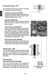
... XD Bit This item is used to 3. Set Limit CPUID Maximum to enable/disable the Hyper-Threading Technology feature. 26 C opyright (C) 2011 American Megatrends, Inc. F-Center CPU Configuration Intel AES-NI CPU Brand Name: Genuine Intel(R) CPU @ 1.80GHz L1 Data Cache 32 KB X 4 L1 Code Cache 32 KB X 4 L2 Cache 256 KB X 4 L3 Cache 8192KB Processor Stepping 2 Max CPU Speed 1800 MHZ Min CPU Speed 1300MHz CPU Speed 1800MHz Processor Cores...
... XD Bit This item is used to 3. Set Limit CPUID Maximum to enable/disable the Hyper-Threading Technology feature. 26 C opyright (C) 2011 American Megatrends, Inc. F-Center CPU Configuration Intel AES-NI CPU Brand Name: Genuine Intel(R) CPU @ 1.80GHz L1 Data Cache 32 KB X 4 L1 Code Cache 32 KB X 4 L2 Cache 256 KB X 4 L3 Cache 8192KB Processor Stepping 2 Max CPU Speed 1800 MHZ Min CPU Speed 1300MHz CPU Speed 1800MHz Processor Cores...
User manual
Page 39
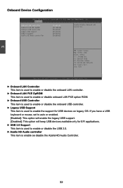
... Controller Enabled] Onboard LAN PXE OpROM Disabled] Onboard USB Controller Enabled] Legacy USB Support Enabled] USB3.0 Support Enabled] Azalia HD Audio controller [Enabled] Enable/Disable Onboard LAN Controller. → ← : Select Screen ↑ ↓ : Select Item Enter: Select +/-: Change Opt. F1: General Help F2: Previous Values F3: Optimized Defaults F4: Save & Exit ESC: Exit Version 2.14.1219. If you have a USB keyboard or mouse, set to enable or disable the USB 3.0. ► Azalia HD Audio controller This item is used to auto or enabled. [Enabled]: This option...
... Controller Enabled] Onboard LAN PXE OpROM Disabled] Onboard USB Controller Enabled] Legacy USB Support Enabled] USB3.0 Support Enabled] Azalia HD Audio controller [Enabled] Enable/Disable Onboard LAN Controller. → ← : Select Screen ↑ ↓ : Select Item Enter: Select +/-: Change Opt. F1: General Help F2: Previous Values F3: Optimized Defaults F4: Save & Exit ESC: Exit Version 2.14.1219. If you have a USB keyboard or mouse, set to enable or disable the USB 3.0. ► Azalia HD Audio controller This item is used to auto or enabled. [Enabled]: This option...

User manual
Page 40
... Megatrends, Inc. Setting options:[Native IDE Mode]; [AHCI];[ RAID]. [Native IDE] - This item is used to set the operating mode of the hardware/software interface between system software and the host controller hardware. The specification includes a description of your SATA drives must also support AHCI. ► SATA Port1/SATA Port2/SATA Port3/SATA Port4/SATA Port5/SATA Port6 Press to go to its specification. Advanced SATA Configuration Onboard SATA Controller Onboard SATA Mode [Enabled] [Native IDE] SATA Ports Device Names if Present and Enabled. ▶ SATA Port1:Not...
... Megatrends, Inc. Setting options:[Native IDE Mode]; [AHCI];[ RAID]. [Native IDE] - This item is used to set the operating mode of the hardware/software interface between system software and the host controller hardware. The specification includes a description of your SATA drives must also support AHCI. ► SATA Port1/SATA Port2/SATA Port3/SATA Port4/SATA Port5/SATA Port6 Press to go to its specification. Advanced SATA Configuration Onboard SATA Controller Onboard SATA Mode [Enabled] [Native IDE] SATA Ports Device Names if Present and Enabled. ▶ SATA Port1:Not...
User manual
Page 42
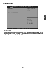
... install a TPM device on the motherboard and set this item to support TPM (Trusted Platform Module) device function. O.S. F1: General Help F2: Previous Values F3: Optimized Defaults F4: Save & Reset ESC: Exit Version 2.14.1219. 3 Trusted Computing Aptio Setup Utility - Current TPM Status Information NO TPM Hardware → ← : Select Screen ↑ ↓ : Select Item Enter: Select +/-: Change Opt. Advanced TPM Configuration TPM SUPPORT [Disabled] Enables or Disables TPM support...
... install a TPM device on the motherboard and set this item to support TPM (Trusted Platform Module) device function. O.S. F1: General Help F2: Previous Values F3: Optimized Defaults F4: Save & Reset ESC: Exit Version 2.14.1219. 3 Trusted Computing Aptio Setup Utility - Current TPM Status Information NO TPM Hardware → ← : Select Screen ↑ ↓ : Select Item Enter: Select +/-: Change Opt. Advanced TPM Configuration TPM SUPPORT [Disabled] Enables or Disables TPM support...
User manual
Page 46
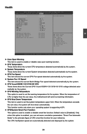
... Temperature CPU Smart Fan Control System Smart Fan Fan Control [Disabled] [Disabled] [Disabled] [Disabled] → ← : Select Screen ↑ ↓ : Select Item Enter: Select +/-: Change Opt. When the temperature exceeds the set value, the system will send out warning information. ► CPU Shut Down Temperature This item is used to set value, the motherboard will shut down automatically. Default value is enabled, you can set the warning temperature for your reference. Only when this option is [Disabled]. This function works...
... Temperature CPU Smart Fan Control System Smart Fan Fan Control [Disabled] [Disabled] [Disabled] [Disabled] → ← : Select Screen ↑ ↓ : Select Item Enter: Select +/-: Change Opt. When the temperature exceeds the set value, the system will send out warning information. ► CPU Shut Down Temperature This item is used to set value, the motherboard will shut down automatically. Default value is enabled, you can set the warning temperature for your reference. Only when this option is [Disabled]. This function works...

User manual
Page 47
... Password Create New Password 40 3 Security Aptio Setup Utility - C opyright (C) 2011 American Megatrends, Inc. If ONLY the Administrator's password is set,then this only limits access to setup and is used to install or change user password. ► HDD BootSector Write This item is used to install or change administrator password. F1: General Help F2: Previous Values F3: Optimized Defaults F4: Save & Exit ESC: Exit Version 2.14.1219. Main F-Center Advanced Boot Power...
... Password Create New Password 40 3 Security Aptio Setup Utility - C opyright (C) 2011 American Megatrends, Inc. If ONLY the Administrator's password is set,then this only limits access to setup and is used to install or change user password. ► HDD BootSector Write This item is used to install or change administrator password. F1: General Help F2: Previous Values F3: Optimized Defaults F4: Save & Exit ESC: Exit Version 2.14.1219. Main F-Center Advanced Boot Power...
User manual
Page 50
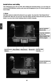
.... Driver Use these options to install all the drivers for your PC screen to guide you how to install it manually. You must click "Intel Chipset Driver" to Install 43 43 4 Install driver and utility This motherboard comes with one DVD, after installing the Operating System, you can simply put it into your DVD-ROM drive, and the main menu will be displayed on each individual driver to install. 1. After that, you can click "One Click Setup...
.... Driver Use these options to install all the drivers for your PC screen to guide you how to install it manually. You must click "Intel Chipset Driver" to Install 43 43 4 Install driver and utility This motherboard comes with one DVD, after installing the Operating System, you can simply put it into your DVD-ROM drive, and the main menu will be displayed on each individual driver to install. 1. After that, you can click "One Click Setup...
User manual
Page 79
... key to use in creating the volume. [↑↓]-Prev/Next [SPACE]-SelectDisk [ENTER]-Done [↑↓]-Change [TAB]-Next [ESC]-Previous Menu [ENTER]-Select 72 Intel(RIn) tMela(Rtr)ixRSatpoirdagSetoMraagneaTgeecrhonpotilongyR-OOMptvio5n.0R.0O.1M01-11I0C.0H.90R.10w3R2AID5 CCooppyyrriigghhtt((CC)) 22000033--1004 IInntteell CCoorrppoorraattiioonn.AlAl Rll iRgihgthstsReRseesrevrevde.d. [ CREATE VOLUME MENU ] Name: TryRAID0 RAID Level: RAID0(Stripe) [ SELECT DISKS ] Port Drive Model Serial...
... key to use in creating the volume. [↑↓]-Prev/Next [SPACE]-SelectDisk [ENTER]-Done [↑↓]-Change [TAB]-Next [ESC]-Previous Menu [ENTER]-Select 72 Intel(RIn) tMela(Rtr)ixRSatpoirdagSetoMraagneaTgeecrhonpotilongyR-OOMptvio5n.0R.0O.1M01-11I0C.0H.90R.10w3R2AID5 CCooppyyrriigghhtt((CC)) 22000033--1004 IInntteell CCoorrppoorraattiioonn.AlAl Rll iRgihgthstsReRseesrevrevde.d. [ CREATE VOLUME MENU ] Name: TryRAID0 RAID Level: RAID0(Stripe) [ SELECT DISKS ] Port Drive Model Serial...

User manual
Page 92
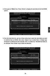
... Non-RAID Disk 74.5GB Non-RAID Disk Select 3 to 6 disks to use Up or Down arrow key to reach the hard disks you want to combine them as RAID5, then press key to use in creating the volume. [↑↓]-Prev/Next [SPACE]-SelectDisk [ENTER]-Done [↑↓]-Change [TAB]-Next [ESC]-Previous Menu [ENTER]-Select 5. Press to "Disks" item. It then goes to display the hard disks list...
... Non-RAID Disk 74.5GB Non-RAID Disk Select 3 to 6 disks to use Up or Down arrow key to reach the hard disks you want to combine them as RAID5, then press key to use in creating the volume. [↑↓]-Prev/Next [SPACE]-SelectDisk [ENTER]-Done [↑↓]-Change [TAB]-Next [ESC]-Previous Menu [ENTER]-Select 5. Press to "Disks" item. It then goes to display the hard disks list...

User manual
Page 102
..., remove the Non-RAID disk, and we will enter BIOS setup. 3. Exit RAID BIOS 1. Recover Volume Options 2. Acceleration Options 6. Physical Devices: ID Device Model 0 ST3320418AS 1 ST3160815AS Serial # 9VM8Y4D8 5RX4M04N Size Type/Status(Vol ID) 298.0GB Non-RAID Disk 149.0GB Non-RAID Disk [↑↓]-Select [ESC]-Exit [ENTER]-Select Menu 2. Exit [ DISK/VOLUME INFORMATION ] RAID Volume : None Defined. Press to start Windows installation. 5 95 Delete RAID Volume 3. Restart computer to exit Intel® Matrix Storage Manager program. Reset Disks...
..., remove the Non-RAID disk, and we will enter BIOS setup. 3. Exit RAID BIOS 1. Recover Volume Options 2. Acceleration Options 6. Physical Devices: ID Device Model 0 ST3320418AS 1 ST3160815AS Serial # 9VM8Y4D8 5RX4M04N Size Type/Status(Vol ID) 298.0GB Non-RAID Disk 149.0GB Non-RAID Disk [↑↓]-Select [ESC]-Exit [ENTER]-Select Menu 2. Exit [ DISK/VOLUME INFORMATION ] RAID Volume : None Defined. Press to start Windows installation. 5 95 Delete RAID Volume 3. Restart computer to exit Intel® Matrix Storage Manager program. Reset Disks...

User manual
Page 103
... RAID driver. 96 When you set the SATA Mode in BIOS to either AHCI or RAID, you need to reboot the system again. Copyright (C) 2010 American Megatrends, Inc. 4. C opyright (C) 2010 American Megatrends, Inc. Main Advanced Chipset Boot Power Health Security Save & Exit Boot Configuration Bootup Numlock State [On] Set the system boot order Quiet Boot [Enabled] CSM16 Module Version 07.63 Boot Option Priorities Boot Option #1 [SATA: ATAPI DVD ...] CD/DVD ROM Drive BBS Priorities → ← : Select Screen...
... RAID driver. 96 When you set the SATA Mode in BIOS to either AHCI or RAID, you need to reboot the system again. Copyright (C) 2010 American Megatrends, Inc. 4. C opyright (C) 2010 American Megatrends, Inc. Main Advanced Chipset Boot Power Health Security Save & Exit Boot Configuration Bootup Numlock State [On] Set the system boot order Quiet Boot [Enabled] CSM16 Module Version 07.63 Boot Option Priorities Boot Option #1 [SATA: ATAPI DVD ...] CD/DVD ROM Drive BBS Priorities → ← : Select Screen...

User manual
Page 104
... type of one or more mass storage devices installed in your system, the following mass storage device(s): * To specify additional SCSI adapters, CD-ROM drivers, or special disk controllers for use with Windows, including those for the following picture appears, press to continue the specific driver installation. Windows Setup Please insert the disk labeled manufacturer-supplied hardware support disk into you do not want to specify additional mass storage devices for use with Windows, press ENTER...
... type of one or more mass storage devices installed in your system, the following mass storage device(s): * To specify additional SCSI adapters, CD-ROM drivers, or special disk controllers for use with Windows, including those for the following picture appears, press to continue the specific driver installation. Windows Setup Please insert the disk labeled manufacturer-supplied hardware support disk into you do not want to specify additional mass storage devices for use with Windows, press ENTER...
User manual
Page 106
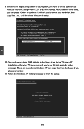
... D. 305251 MB Disk 0 at id 0 on bus 0 on this computer. Follow the Windows XP install processes to continue. It will display the partition of your hard disk, then copy files...etc., until the whole Windows is setup. Windows XP Professional Setup Insert the disk labeled: Intel Matrix Storage Manager driver into drive A: * Press ENTER when ready F3=Quit ENTER=Continue 99 Windows XP Professional Setup The following list shows the existing...
... D. 305251 MB Disk 0 at id 0 on bus 0 on this computer. Follow the Windows XP install processes to continue. It will display the partition of your hard disk, then copy files...etc., until the whole Windows is setup. Windows XP Professional Setup Insert the disk labeled: Intel Matrix Storage Manager driver into drive A: * Press ENTER when ready F3=Quit ENTER=Continue 99 Windows XP Professional Setup The following list shows the existing...


