
English manual
Page 4
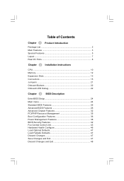
... List 2 Main Features 3 Special Features 5 Layout ...7 Rear I/O Ports 8 Chapter 2 Installation Instructions CPU ...10 Memory 12 Expansion Slots 13 Connectors 15 Jumpers 21 Onboard Buttons 22 Onboard LED Debug 22 Chapter 3 BIOS Description Enter BIOS Setup 24 Main menu 24 Standard BIOS Features 26 Advanced BIOS Features 26 Advanced Chipset Features 32 PCI/PNP Resource Management 35 Boot Configuration Features 36 Power Management Features 38 BIOS Security Features 42 Fox Central Control Unit 43 Hardware Health Configure 46 Load Optimal Defaults 47 Load Failsafe Defaults...
... List 2 Main Features 3 Special Features 5 Layout ...7 Rear I/O Ports 8 Chapter 2 Installation Instructions CPU ...10 Memory 12 Expansion Slots 13 Connectors 15 Jumpers 21 Onboard Buttons 22 Onboard LED Debug 22 Chapter 3 BIOS Description Enter BIOS Setup 24 Main menu 24 Standard BIOS Features 26 Advanced BIOS Features 26 Advanced Chipset Features 32 PCI/PNP Resource Management 35 Boot Configuration Features 36 Power Management Features 38 BIOS Security Features 42 Fox Central Control Unit 43 Hardware Health Configure 46 Load Optimal Defaults 47 Load Failsafe Defaults...
English manual
Page 5
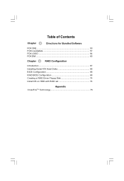
Table of Contents Chapter 4 Directions for Bundled Software FOX ONE 50 FOX LiveUpdate 57 FOX LOGO 64 FOX DMI 65 Chapter 5 RAID Configuration Introduction 67 Installing Serial ATA Hard Disks 68 BIOS Configuration 68 RAID BIOS Configuration 68 Creating a RAID Driver Floppy Disk 74 Install OS on HDD with RAID set 74 Appendix CrossFireTM Technology 76
Table of Contents Chapter 4 Directions for Bundled Software FOX ONE 50 FOX LiveUpdate 57 FOX LOGO 64 FOX DMI 65 Chapter 5 RAID Configuration Introduction 67 Installing Serial ATA Hard Disks 68 BIOS Configuration 68 RAID BIOS Configuration 68 Creating a RAID Driver Floppy Disk 74 Install OS on HDD with RAID set 74 Appendix CrossFireTM Technology 76

English manual
Page 6
... overclock. Attention: The pictures of objects used in this motherboard. Please refer to the motherboard and CPU due high temperatures. 3. W e do not guarantee that your system or memory module. Attention: Please visit the Foxconn English website (http://www.foxconnchannel. It is just for this manual are upgraded from time to download the latest BIOS file and drivers for reference. Failure to switch off before inserting or removing expansion cards...
... overclock. Attention: The pictures of objects used in this motherboard. Please refer to the motherboard and CPU due high temperatures. 3. W e do not guarantee that your system or memory module. Attention: Please visit the Foxconn English website (http://www.foxconnchannel. It is just for this manual are upgraded from time to download the latest BIOS file and drivers for reference. Failure to switch off before inserting or removing expansion cards...
English manual
Page 15
Caution should be exercised during the installation of the CPU, memory, power supply, slots, and pin headers, an d the mounting o f jumpers. This chapter includes the following information: v CPU v Memory v Expansion Slots v Connectors v Jumpers v Onboard Buttons v Onboard LED Debug 9 Please refer to the motherboard layout prior to any installation and read the contents in this chapter carefully. Chapter 1 Product Introduction 2 Chapter This chapter introduces the hardware installation process, including the installation of these modules.
Caution should be exercised during the installation of the CPU, memory, power supply, slots, and pin headers, an d the mounting o f jumpers. This chapter includes the following information: v CPU v Memory v Expansion Slots v Connectors v Jumpers v Onboard Buttons v Onboard LED Debug 9 Please refer to the motherboard layout prior to any installation and read the contents in this chapter carefully. Chapter 1 Product Introduction 2 Chapter This chapter introduces the hardware installation process, including the installation of these modules.

English manual
Page 17
... to your CPU fan user guide for correct installation. 11 Close the load plate, and slightly push down without tilting or sliding the CPU in order to prevent overheating and damage to protect the contacts of the socket. Please refer to socket cutouts. Chapter 2 Installation Instructions 3. Alignment Key Pin 1 position Socket Cutouts 4. Always replace the socket cover if the CPU is used to the CPU. The alignment key also provides...
... to your CPU fan user guide for correct installation. 11 Close the load plate, and slightly push down without tilting or sliding the CPU in order to prevent overheating and damage to protect the contacts of the socket. Please refer to socket cutouts. Chapter 2 Installation Instructions 3. Alignment Key Pin 1 position Socket Cutouts 4. Always replace the socket cover if the CPU is used to the CPU. The alignment key also provides...
English manual
Page 19
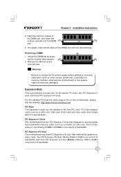
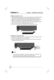
... detailed PCI Express cards support list on this motherboard, please visit the website: http://www.foxconnchannel.com PCI Slots The expansion cards can be seriously damaged. PCI Express x16 Slots This motherboard has three PCI Express x16 slots that comply with PCI specifications. Remove the Memory bank from the slot. Chapter 2 Installation Instructions 2. The plastic clips at both sides of bandwidth. Expansion Slots This motherboard includes two 32-bit master PCI slots, two PCI Express x1 slots and three PCI Express x16 slots. Warning...
... detailed PCI Express cards support list on this motherboard, please visit the website: http://www.foxconnchannel.com PCI Slots The expansion cards can be seriously damaged. PCI Express x16 Slots This motherboard has three PCI Express x16 slots that comply with PCI specifications. Remove the Memory bank from the slot. Chapter 2 Installation Instructions 2. The plastic clips at both sides of bandwidth. Expansion Slots This motherboard includes two 32-bit master PCI slots, two PCI Express x1 slots and three PCI Express x16 slots. Warning...
English manual
Page 20
... can remove the expansion card from the slot. Uninstalling an expansion card 1. Note: If a performance graphics card was installed into x16 PCI Express slot, 24-pin power supply was recommended. 14 Make sure to unplug the power cord before adding any expansion cards, Remove the bracket on the real panel. 3. Align the card with the interface of the chassis with and make the necessary hardware settings for the card. 2. Secure the card...
... can remove the expansion card from the slot. Uninstalling an expansion card 1. Note: If a performance graphics card was installed into x16 PCI Express slot, 24-pin power supply was recommended. 14 Make sure to unplug the power cord before adding any expansion cards, Remove the bracket on the real panel. 3. Align the card with the interface of the chassis with and make the necessary hardware settings for the card. 2. Secure the card...
English manual
Page 22
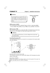
... the connector to the case's IDE indicator LED indicating the activity status of the case; the system will restart when the switch is pressed. 16 Front Panel Connector: FP1 This motherboard includes one connector for connecting the front panel switch and LED indicators. 1 + HD_LED - 2 + - Empty Front Panel Connector Hard Disk LED Connector (HD_LED) The connector connects to the Reset switch on the front panel of hard disks. If you want to use 8-pin ATX 12V power supply. Chapter 2 Installation Instructions Attention: We recommend you use 4-pin power supply...
... the connector to the case's IDE indicator LED indicating the activity status of the case; the system will restart when the switch is pressed. 16 Front Panel Connector: FP1 This motherboard includes one connector for connecting the front panel switch and LED indicators. 1 + HD_LED - 2 + - Empty Front Panel Connector Hard Disk LED Connector (HD_LED) The connector connects to the Reset switch on the front panel of hard disks. If you want to use 8-pin ATX 12V power supply. Chapter 2 Installation Instructions Attention: We recommend you use 4-pin power supply...

English manual
Page 23
... allows up to the power LED on and off . Chapter 2 Installation Instructions Power LED Connector (PW R_LED) Attach the connector to 300MB/s data transfer rate. When the system is in S1 status, the LED is off rather than using the power supply button. Power Switch Connector (PWRSW) Attach the connector to the power button of the case. These connectors support the thin Serial ATA II cables for Serial ATA II devices. The Power LED indicates the system's status...
... allows up to the power LED on and off . Chapter 2 Installation Instructions Power LED Connector (PW R_LED) Attach the connector to 300MB/s data transfer rate. When the system is in S1 status, the LED is off rather than using the power supply button. Power Switch Connector (PWRSW) Attach the connector to the power button of the case. These connectors support the thin Serial ATA II cables for Serial ATA II devices. The Power LED indicates the system's status...
English manual
Page 24
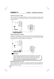
... marker of motherboard also have two 10-pin headers onboard, which may be connected to either the front (provided that the front panel of your chassis is for a serial (COM) port. make sure to provide additional four USB ports. Connect the serial port module cable to the connector, then install the module to the USB ports on the rear panel, this series of each USB pin headers correctly, otherwise the USB ports will not work. USB 2.0 Connectors Warning: 10...
... marker of motherboard also have two 10-pin headers onboard, which may be connected to either the front (provided that the front panel of your chassis is for a serial (COM) port. make sure to provide additional four USB ports. Connect the serial port module cable to the connector, then install the module to the USB ports on the rear panel, this series of each USB pin headers correctly, otherwise the USB ports will not work. USB 2.0 Connectors Warning: 10...
English manual
Page 27
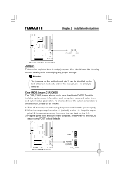
... pins 2-3 (default) to load defaults. 1 Clear 1 Normal (default) Clear CMOS Jumper CLR_ CMOS 21 Attention The jumpers on the computer, press to enter BIOS setup during POST to pins 1-2. The data includes system setup information such as follows: 1. Chapter 2 Installation Instructions 1 INTRUDERJ GND INTR Chassis Intruder Connector Jumpers This section explains how to modifying any jumper settings. Move the jumper cap from the power supply. 2. Clear CMOS Jumper: CLR_CMOS The CLR_CMOS jumper allows you to it. Plug the power cord and turn on the motherboard, pin...
... pins 2-3 (default) to load defaults. 1 Clear 1 Normal (default) Clear CMOS Jumper CLR_ CMOS 21 Attention The jumpers on the computer, press to enter BIOS setup during POST to pins 1-2. The data includes system setup information such as follows: 1. Chapter 2 Installation Instructions 1 INTRUDERJ GND INTR Chassis Intruder Connector Jumpers This section explains how to modifying any jumper settings. Move the jumper cap from the power supply. 2. Clear CMOS Jumper: CLR_CMOS The CLR_CMOS jumper allows you to it. Plug the power cord and turn on the motherboard, pin...

English manual
Page 29
... system settings through the BIOS Setup menus. You want to change the default CMOS settings. This chapter includes the following cases occur: 1. You have to run the Setup Program when the following information: v Enter BIOS Setup v Main Menu v Standard BIOS Features v Advanced BIOS Features v Advanced Chipset Features v PCI/PNP Resource Management v Boot Configuration Features v Power Management Features v BIOS Security Features v Fox Central Control Unit v Hardware Health Configure v Load Optimal Defaults v Load Failsafe Defaults v Discard Changes v Save Changes and...
... system settings through the BIOS Setup menus. You want to change the default CMOS settings. This chapter includes the following cases occur: 1. You have to run the Setup Program when the following information: v Enter BIOS Setup v Main Menu v Standard BIOS Features v Advanced BIOS Features v Advanced Chipset Features v PCI/PNP Resource Management v Boot Configuration Features v Power Management Features v BIOS Security Features v Fox Central Control Unit v Hardware Health Configure v Load Optimal Defaults v Load Failsafe Defaults v Discard Changes v Save Changes and...
English manual
Page 31
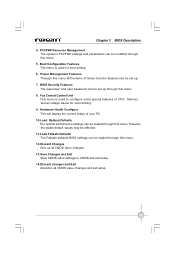
... and user password can be set up all voltage values for boot setting. 6. Boot Configuration Features The menu is used for overclocking. 9. Fox Central Control Unit This menu is used to CMOS and exit setup. 14.Discard changes and Exit Abandon all CMOS value changes and exit setup. 25 Hardware Health Configure This will display the current status of your PC. 10.Load Optimal Defaults The optimal performance settings can be loaded through this menu. 8. Chapter 3 BIOS Description 4. Power...
... and user password can be set up all voltage values for boot setting. 6. Boot Configuration Features The menu is used for overclocking. 9. Fox Central Control Unit This menu is used to CMOS and exit setup. 14.Discard changes and Exit Abandon all CMOS value changes and exit setup. 25 Hardware Health Configure This will display the current status of your PC. 10.Load Optimal Defaults The optimal performance settings can be loaded through this menu. 8. Chapter 3 BIOS Description 4. Power...
English manual
Page 34
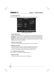
... ownership change should claim by EHCI driver. 2.2.1 USB Mass Storage Device Press to go to utilize during boot and while using DOS. [Auto]: auto detects USB keyboard or mouse and if found, allows it to the next page sub menu. Chapter 3 BIOS Description 2.2 USB Configuration Scroll to this item and press to view the following screen: USB Configuration Menu vLegacy USB Support Legacy USB support refers to the USB mouse and USB keyboard support. [Disabled]: to prevent the use of any USB device...
... ownership change should claim by EHCI driver. 2.2.1 USB Mass Storage Device Press to go to utilize during boot and while using DOS. [Auto]: auto detects USB keyboard or mouse and if found, allows it to the next page sub menu. Chapter 3 BIOS Description 2.2 USB Configuration Scroll to this item and press to view the following screen: USB Configuration Menu vLegacy USB Support Legacy USB support refers to the USB mouse and USB keyboard support. [Disabled]: to prevent the use of any USB device...
English manual
Page 35
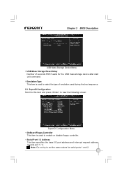
... enable or disable floppy controller. Note: Do not try to set the same values for the USB mass storage device after start unit command. Chapter 3 BIOS Description USB Mass Storage Device Menu vUSB Mass Storage Reset Delay Number of emulation used during the boot sequence. 2.3 SuperIO Configuration Scroll to this item and press to view the following screen: SuperIO Configuration Menu vOnBoard Floppy Controller This item is used to select the type of seconds POST waits for serial ports...
... enable or disable floppy controller. Note: Do not try to set the same values for the USB mass storage device after start unit command. Chapter 3 BIOS Description USB Mass Storage Device Menu vUSB Mass Storage Reset Delay Number of emulation used during the boot sequence. 2.3 SuperIO Configuration Scroll to this item and press to view the following screen: SuperIO Configuration Menu vOnBoard Floppy Controller This item is used to select the type of seconds POST waits for serial ports...
English manual
Page 38
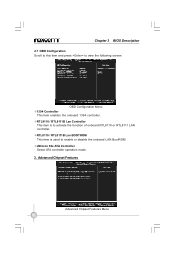
vRTL8110 / RTL8111B Lan BOOTROM This item is to enable or disable the onboard LAN BootROM. vJMicron 36x ATA Controller Select ATA controller operation mode. 3. Advanced Chipset Features Advanced Chipset Features Menu 32 vRTL8110 / RTL8111B Lan Controller This item is used to activate the function of onboard RTL8110 or RTL8111 LAN controller. Chapter 3 BIOS Description 2.7 OBD Configuration Scroll to this item and press to view the following screen: OBD Configuration Menu v1394 Controller This item enables the onboard 1394 controller.
vRTL8110 / RTL8111B Lan BOOTROM This item is to enable or disable the onboard LAN BootROM. vJMicron 36x ATA Controller Select ATA controller operation mode. 3. Advanced Chipset Features Advanced Chipset Features Menu 32 vRTL8110 / RTL8111B Lan Controller This item is used to activate the function of onboard RTL8110 or RTL8111 LAN controller. Chapter 3 BIOS Description 2.7 OBD Configuration Scroll to this item and press to view the following screen: OBD Configuration Menu v1394 Controller This item enables the onboard 1394 controller.
English manual
Page 40
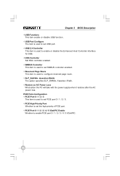
... The option specifies SLP_S4#Min. vHDA Controller Set HDA controller enabled. PCIE Ports Configuration vPCIE Port 0 / 1 / 2 / 3 This item is used to set PCIE port 0 / 1 / 2 / 3. vSMBUS Controller This item is used to enable or disable the Enhanced Host Controller Interface for USB. Assertion W idth. Chapter 3 BIOS Description vUSB Functions This item enable or disable USB function. vPCIE Port 0 / 1 / 2 / 3 / 4 / 5 IOxAPIC Enable Whether to configure reserved page route. vPCIE High Priority Port Whether to set the high priority of PCIE port. vRestore on AC Power Loss...
... The option specifies SLP_S4#Min. vHDA Controller Set HDA controller enabled. PCIE Ports Configuration vPCIE Port 0 / 1 / 2 / 3 This item is used to set PCIE port 0 / 1 / 2 / 3. vSMBUS Controller This item is used to enable or disable the Enhanced Host Controller Interface for USB. Assertion W idth. Chapter 3 BIOS Description vUSB Functions This item enable or disable USB function. vPCIE Port 0 / 1 / 2 / 3 / 4 / 5 IOxAPIC Enable Whether to configure reserved page route. vPCIE High Priority Port Whether to set the high priority of PCIE port. vRestore on AC Power Loss...
English manual
Page 49
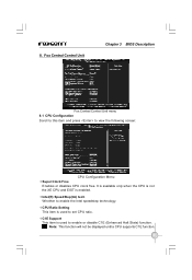
... displayed until a CPU supports C1E function. 43 Fox Central Control Unit Chapter 3 BIOS Description Fox Central Control Unit menu 8.1 CPU Configuration Scroll to this item and press to enable or disable C1E (Enhanced Halt State) function. It is available only when the CPU is not the XE CPU and EIST is used to view the following screen: CPU Configuration Menu vSuper Clock Free Enables or disables CPU clock free. vIntel(R) SpeedStep(tm) tech W hether to set CPU...
... displayed until a CPU supports C1E function. 43 Fox Central Control Unit Chapter 3 BIOS Description Fox Central Control Unit menu 8.1 CPU Configuration Scroll to this item and press to enable or disable C1E (Enhanced Halt State) function. It is available only when the CPU is not the XE CPU and EIST is used to view the following screen: CPU Configuration Menu vSuper Clock Free Enables or disables CPU clock free. vIntel(R) SpeedStep(tm) tech W hether to set CPU...

English manual
Page 74
...setting and then exit the BIOS setup program. Connect SATA power cable to SATA hard disk. 3. Enter the BIOS setup by pressing keys W hen the following message appears on the screen During the POST: Press the to enter Configuration Utility. Creating RAID 0 1. Connect one end of the SATA cable to motherboard's SATA onnectors and the end to the power connector of SATA hard disk. RAID BIOS Configuration Enter RAID BIOS Setup Enter the Intel® Matrix Storage Manager Option ROM Utility main menu by pressing key during the POST. 2. Chapter 5 RAID Configuration Installing Serial...
...setting and then exit the BIOS setup program. Connect SATA power cable to SATA hard disk. 3. Enter the BIOS setup by pressing keys W hen the following message appears on the screen During the POST: Press the to enter Configuration Utility. Creating RAID 0 1. Connect one end of the SATA cable to motherboard's SATA onnectors and the end to the power connector of SATA hard disk. RAID BIOS Configuration Enter RAID BIOS Setup Enter the Intel® Matrix Storage Manager Option ROM Utility main menu by pressing key during the POST. 2. Chapter 5 RAID Configuration Installing Serial...
English manual
Page 80
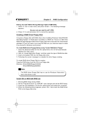
... RAID Drive Floppy", and then select the type of RAID drive disk. 3. Entering BIOS Setup during POST. 2. Exit" in Windows environment: To create RAID deiver Floppy Disk by yourself in main menu and press , The following picture appears, press , then insert the RAID driver FDD to complete the drive floppy creating. There is a 32bit Intel Matrix Storage Manager RAID Driver Floppy Disk that is included in -box driver it by using "Create RAID Drive Floppy" 1. Insert a formatted FDD into the floppy disk drive. 4. Chapter 5 RAID Configuration...
... RAID Drive Floppy", and then select the type of RAID drive disk. 3. Entering BIOS Setup during POST. 2. Exit" in Windows environment: To create RAID deiver Floppy Disk by yourself in main menu and press , The following picture appears, press , then insert the RAID driver FDD to complete the drive floppy creating. There is a 32bit Intel Matrix Storage Manager RAID Driver Floppy Disk that is included in -box driver it by using "Create RAID Drive Floppy" 1. Insert a formatted FDD into the floppy disk drive. 4. Chapter 5 RAID Configuration...


