
English manual
Page 4
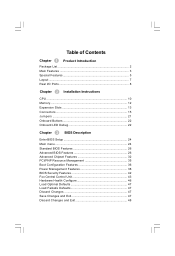
Table of Contents Chapter 1 Product Introduction Package List 2 Main Features 3 Special Features 5 Layout ...7 Rear I/O Ports 8 Chapter 2 Installation Instructions CPU ...10 Memory 12 Expansion Slots 13 Connectors 15 Jumpers 21 Onboard Buttons 22 Onboard LED Debug 22 Chapter 3 BIOS Description Enter BIOS Setup 24 Main menu 24 ...
Table of Contents Chapter 1 Product Introduction Package List 2 Main Features 3 Special Features 5 Layout ...7 Rear I/O Ports 8 Chapter 2 Installation Instructions CPU ...10 Memory 12 Expansion Slots 13 Connectors 15 Jumpers 21 Onboard Buttons 22 Onboard LED Debug 22 Chapter 3 BIOS Description Enter BIOS Setup 24 Main menu 24 ...

English manual
Page 6
... Attention: W e cannot guarantee that the content of this manual will operate normally while overclock. Attention: 1. W e do not guarantee that your reference. Attention: Please visit the Foxconn English website (http://www.foxconnchannel. Normal operation depends on the machine if the CPU fan is suggested to select high-quality, certified fans in serious...in this manual are upgraded from time to switch off before inserting or removing expansion cards or other peripherals, especially when you insert or remove a memory module. Attention: The pictures of your system or...
... Attention: W e cannot guarantee that the content of this manual will operate normally while overclock. Attention: 1. W e do not guarantee that your reference. Attention: Please visit the Foxconn English website (http://www.foxconnchannel. Normal operation depends on the machine if the CPU fan is suggested to select high-quality, certified fans in serious...in this manual are upgraded from time to switch off before inserting or removing expansion cards or other peripherals, especially when you insert or remove a memory module. Attention: The pictures of your system or...
English manual
Page 9
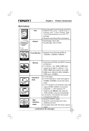
... upcoming 45nm processors Northbridge: Intel® X38 Southbridge: Intel® ICH9R Front Side Bus Supports Front Side Bus(FSB) at 1333MHz / 1066MHz / 800MHz Memory Dual-Channel DDR2 and DDR3 memory architecture 4 x 240-pin, 1.8V, DDR2 DIMM slots support up to 8GB; 2 x 240-pin, 1.5V, DDR3 DIMM slots support up to 4GB DDR2...
... upcoming 45nm processors Northbridge: Intel® X38 Southbridge: Intel® ICH9R Front Side Bus Supports Front Side Bus(FSB) at 1333MHz / 1066MHz / 800MHz Memory Dual-Channel DDR2 and DDR3 memory architecture 4 x 240-pin, 1.8V, DDR2 DIMM slots support up to 8GB; 2 x 240-pin, 1.5V, DDR3 DIMM slots support up to 4GB DDR2...

English manual
Page 11
.... Ferrite Choke FOX ONE Ferrite Choke design holds energy at a higher frequency than traditional iron cores, resulting in less power loss and more online with memory. CONNECTIVITY FOR THE DIGITAL WORLD Dual eSATA Dual eSATA ports located on the next page) 5 Onboard chipset and W indows-based control panel for easy overclocking...
.... Ferrite Choke FOX ONE Ferrite Choke design holds energy at a higher frequency than traditional iron cores, resulting in less power loss and more online with memory. CONNECTIVITY FOR THE DIGITAL WORLD Dual eSATA Dual eSATA ports located on the next page) 5 Onboard chipset and W indows-based control panel for easy overclocking...
English manual
Page 15
Chapter 1 Product Introduction 2 Chapter This chapter introduces the hardware installation process, including the installation of these modules. This chapter includes the following information: v CPU v Memory v Expansion Slots v Connectors v Jumpers v Onboard Buttons v Onboard LED Debug 9 Caution should be exercised during the installation of the CPU, memory, power supply, slots, and pin headers, an d the mounting o f jumpers. Please refer to the motherboard layout prior to any installation and read the contents in this chapter carefully.
Chapter 1 Product Introduction 2 Chapter This chapter introduces the hardware installation process, including the installation of these modules. This chapter includes the following information: v CPU v Memory v Expansion Slots v Connectors v Jumpers v Onboard Buttons v Onboard LED Debug 9 Caution should be exercised during the installation of the CPU, memory, power supply, slots, and pin headers, an d the mounting o f jumpers. Please refer to the motherboard layout prior to any installation and read the contents in this chapter carefully.
English manual
Page 18
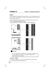
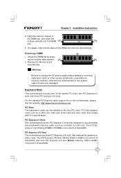
... 240-pin DDR3 DIMM Slots Warning: Do not install DDR2 and DDR3 memory modules simultaneously on this motherboard, doing so may result in one memory bank to the motherboard and your system. For the detailed memory support list on this motherboard, please visit the website: http://www.foxconnchannel....com The figures illustrate the location of the DIMM slot, and the memory module can be fixed in damage...
... 240-pin DDR3 DIMM Slots Warning: Do not install DDR2 and DDR3 memory modules simultaneously on this motherboard, doing so may result in one memory bank to the motherboard and your system. For the detailed memory support list on this motherboard, please visit the website: http://www.foxconnchannel....com The figures illustrate the location of the DIMM slot, and the memory module can be fixed in damage...
English manual
Page 19
... Warning: Be sure to accommodate less bandwidth-intensive cards, such as a LAN card, USB card, SCSI card and other system peripherals, especially the memory modules, otherwise the motherboard or the system might be installed in the two PCI slots. The PCI Express x1 slot offering 250MB/s (500MB/s concurrent... to unplug the AC power supply before adding or removing expansion cards or other cards that reserved for graphics or video cards. Align the memory module to the DIMM slot, and insert the module vertically into the DIMM slot. 3. ing the module clips outward. 2. For the ...
... Warning: Be sure to accommodate less bandwidth-intensive cards, such as a LAN card, USB card, SCSI card and other system peripherals, especially the memory modules, otherwise the motherboard or the system might be installed in the two PCI slots. The PCI Express x1 slot offering 250MB/s (500MB/s concurrent... to unplug the AC power supply before adding or removing expansion cards or other cards that reserved for graphics or video cards. Align the memory module to the DIMM slot, and insert the module vertically into the DIMM slot. 3. ing the module clips outward. 2. For the ...
English manual
Page 31
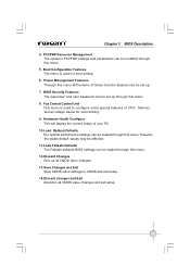
....Discard Changes Give up all CMOS value changes. 13.Save Changes and Exit Save CMOS value settings to configure some special features of CPU、Memory and all voltage values for boot setting. 6. Hardware Health Configure This will display the current status of Green function features can be modified through this...
....Discard Changes Give up all CMOS value changes. 13.Save Changes and Exit Save CMOS value settings to configure some special features of CPU、Memory and all voltage values for boot setting. 6. Hardware Health Configure This will display the current status of Green function features can be modified through this...
English manual
Page 39
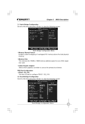
Chapter 3 BIOS Description 3.1 North Bridge Configuration Scroll to this item and press to use of overlapped PCI memory above the total physical memory. vMemory Hole This reserves the 15MB to allow remapping of ISA expan sion card. PEG Port Configuration vPEI-E1 / E2_X16 This item is used to ... Configuration Menu 33 vInitate Graphic Adapter Select which graphics controller to view the following screen: North Bridge Configuration Menu vMemory Remap Feature Enable to 16MB memory address space for use as the primary boot device.
Chapter 3 BIOS Description 3.1 North Bridge Configuration Scroll to this item and press to use of overlapped PCI memory above the total physical memory. vMemory Hole This reserves the 15MB to allow remapping of ISA expan sion card. PEG Port Configuration vPEI-E1 / E2_X16 This item is used to ... Configuration Menu 33 vInitate Graphic Adapter Select which graphics controller to view the following screen: North Bridge Configuration Menu vMemory Remap Feature Enable to 16MB memory address space for use as the primary boot device.
English manual
Page 42
.... Chapter 3 BIOS Description vIRQ3 / 4 / 5 / 7 / 9 / 10 / 11 / 14 / 15 & DMA Channel 0 / 1 / 3 / 5 / 6 / 7 The items are for legacy ISA devices. 5. vReserved Memory Size This item is available to be used to set the size of memory block to reserve for IRQ / DMA to decide whether or not to be modified between POST messages or OEM...
.... Chapter 3 BIOS Description vIRQ3 / 4 / 5 / 7 / 9 / 10 / 11 / 14 / 15 & DMA Channel 0 / 1 / 3 / 5 / 6 / 7 The items are for legacy ISA devices. 5. vReserved Memory Size This item is available to be used to set the size of memory block to reserve for IRQ / DMA to decide whether or not to be modified between POST messages or OEM...
English manual
Page 43
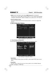
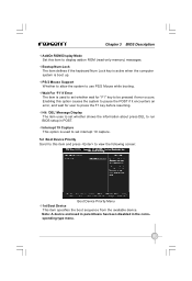
... this option causes the system to pause the POST if it encounters an error, and wait for "F1" key to display addon ROM (read-only memory) messages.
... this option causes the system to pause the POST if it encounters an error, and wait for "F1" key to display addon ROM (read-only memory) messages.
English manual
Page 50
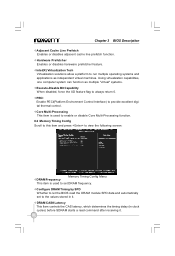
... prefetcher feature. vCore Multi-Processing This item is used to enable or disable Core Multi-Processing function. 8.2 Memory Timing Config Scroll to this item and press to view the following screen: vDRAM Frequency Memory Timing Config Menu This item is used to provide excellent digital thermal control. Chapter 3 BIOS Description vAdjacent Cache...
... prefetcher feature. vCore Multi-Processing This item is used to enable or disable Core Multi-Processing function. 8.2 Memory Timing Config Scroll to this item and press to view the following screen: vDRAM Frequency Memory Timing Config Menu This item is used to provide excellent digital thermal control. Chapter 3 BIOS Description vAdjacent Cache...

English manual
Page 51
...time (in clock cycles). CPU Voltage Margining offset = 12.5mV x Step. vMemory / NB / SB / FSB Voltage Control This item is used to change Memory / NB / SB / FSB Voltage. 8.4 Fox Intelligent Stepping You can select different overclocking options by this item and press to view the following screen: All Voltage...Voltage Control Scroll to this item. 8.5 ******* Ratio and Clock Setting ******* vCPU Frequency Setting This item is used to set CPU frequency. vCPU Frequency : Memory Speed The option specifies CPU frequency : memory speed. vPCI Clock This item is used to set PCI clock. 45
...time (in clock cycles). CPU Voltage Margining offset = 12.5mV x Step. vMemory / NB / SB / FSB Voltage Control This item is used to change Memory / NB / SB / FSB Voltage. 8.4 Fox Intelligent Stepping You can select different overclocking options by this item and press to view the following screen: All Voltage...Voltage Control Scroll to this item. 8.5 ******* Ratio and Clock Setting ******* vCPU Frequency Setting This item is used to set CPU frequency. vCPU Frequency : Memory Speed The option specifies CPU frequency : memory speed. vPCI Clock This item is used to set PCI clock. 45

English manual
Page 59
... changes Apply the changes 4.1 Limit Setting - Show current CPU Go to Freq. Chapter 4 Directions for Bundled Software 3. Frequency Control This page enables you to set memory and PCI Express frequency manually. Freq.
... changes Apply the changes 4.1 Limit Setting - Show current CPU Go to Freq. Chapter 4 Directions for Bundled Software 3. Frequency Control This page enables you to set memory and PCI Express frequency manually. Freq.

English manual
Page 62
Fan Page - Voltage Page - Go to Fan page W hether to set Adjust by dragging the lever Reset the changes Apply the changes 56 Chapter 4 Directions for Bundled Software 5. Go to Voltage page Select the option you to set fan speed manually. Fan Control This page helps you want to enable smart fan function Set fan speed by manual Reset the changes Apply the changes 6. Voltage Control This page is used to enable smart fan function or set CPU voltage, memory voltage and northbridge voltage manually.
Fan Page - Voltage Page - Go to Fan page W hether to set Adjust by dragging the lever Reset the changes Apply the changes 56 Chapter 4 Directions for Bundled Software 5. Go to Voltage page Select the option you to set fan speed manually. Fan Control This page helps you want to enable smart fan function Set fan speed by manual Reset the changes Apply the changes 6. Voltage Control This page is used to enable smart fan function or set CPU voltage, memory voltage and northbridge voltage manually.
English manual
Page 71
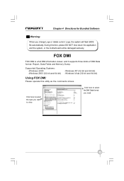
... BIOS file automatically. FOX DMI FOX DMI is a full DMI information viewer, and it supports three kinds of DMI Data format: Report, Data Fields and Memory Dump. Click here to view. During this utility as the comments shows . Click here to select the DMI Data format you want to select the...
... BIOS file automatically. FOX DMI FOX DMI is a full DMI information viewer, and it supports three kinds of DMI Data format: Report, Data Fields and Memory Dump. Click here to view. During this utility as the comments shows . Click here to select the DMI Data format you want to select the...
