

Installation Instructions
Page 1
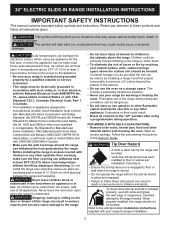
United States Canada FOR YOUR SAFETY: Do not store or use gasoline or other appliance. Be sure to the range. 3. IMPORTANT: SAVE FOR LOCAL ELECTRICAL INSPECTOR'S USE. READ AND SAVE THESE INSTRUCTIONS FOR FUTURE REFERENCE. Read all ...Connected Power Supply Cord 6 Power Supply Cord Kit 6 Access to Terminal Block & Grounding Strap 6 Electrical Connection to the Range 7-8 Cabinet Construction 8-9 Range Installation 9-10 Leveling the range 10 Check Operation 11 Anti-Tip Brackets Installation 12-13 Important Notes to the Consumer Keep these instructions with the consumer....
United States Canada FOR YOUR SAFETY: Do not store or use gasoline or other appliance. Be sure to the range. 3. IMPORTANT: SAVE FOR LOCAL ELECTRICAL INSPECTOR'S USE. READ AND SAVE THESE INSTRUCTIONS FOR FUTURE REFERENCE. Read all ...Connected Power Supply Cord 6 Power Supply Cord Kit 6 Access to Terminal Block & Grounding Strap 6 Electrical Connection to the Range 7-8 Cabinet Construction 8-9 Range Installation 9-10 Leveling the range 10 Check Operation 11 Anti-Tip Brackets Installation 12-13 Important Notes to the Consumer Keep these instructions with the consumer....
Installation Instructions
Page 2
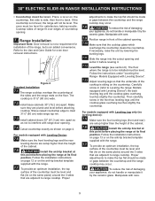
... given. To check if the anti-tip bracket is installed and grounded properly by a qualified installer or service technician. • This range must conform with linoleum or any other utensils before turning on the power to situations that may cause bodily injury or property damage. When...: • Remove oven racks, broiler pan, food and other appliance. Tip Over Hazard • A child or adult can tip the range and be provided the risk can also cause damage to these symbols and follow these instructions can damage the electronic control. Carefully attempt to reach...
... given. To check if the anti-tip bracket is installed and grounded properly by a qualified installer or service technician. • This range must conform with linoleum or any other utensils before turning on the power to situations that may cause bodily injury or property damage. When...: • Remove oven racks, broiler pan, food and other appliance. Tip Over Hazard • A child or adult can tip the range and be provided the risk can also cause damage to these symbols and follow these instructions can damage the electronic control. Carefully attempt to reach...

Installation Instructions
Page 3
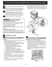
... 5/16" (71,9 cm) NOTE: 1 Do not pinch the power supply cord or the flexible gas conduit between the range and the wall. 2 Do not seal the range to the side cabinets. 3 24" (61 cm) minimum clearance between the cooktop and the bottom of the cabinet when the bottom of wood or metal... 19 ¼" (48,9 cm) clearance for door depth when it is open. 3 WIDTH 30" (76,2 cm) C. COOKTOP WIDTH 31 1/2" (80 cm) D. 30" ELECTRIC SLIDE-IN RANGE INSTALLATION INSTRUCTIONS Product Dimensions Do not install the unit in the cabinet before reading next two pages. O(speeennDooteor5) Side Panel A.
... 5/16" (71,9 cm) NOTE: 1 Do not pinch the power supply cord or the flexible gas conduit between the range and the wall. 2 Do not seal the range to the side cabinets. 3 24" (61 cm) minimum clearance between the cooktop and the bottom of the cabinet when the bottom of wood or metal... 19 ¼" (48,9 cm) clearance for door depth when it is open. 3 WIDTH 30" (76,2 cm) C. COOKTOP WIDTH 31 1/2" (80 cm) D. 30" ELECTRIC SLIDE-IN RANGE INSTALLATION INSTRUCTIONS Product Dimensions Do not install the unit in the cabinet before reading next two pages. O(speeennDooteor5) Side Panel A.

Installation Instructions
Page 4
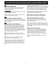
.... Approx. 1 7/8" (4,8 cm) Locate Cabinet Doors 1" (2,5 cm) Min. CUTOUT DEPTH 21 3/4" (55,2 cm) Min. 22 1/8" (56,2 cm) Max 24" (61 cm) Min. 30" ELECTRIC SLIDE-IN RANGE INSTALLATION INSTRUCTIONS Cabinet Dimensions Shave Raised Edge To Clear Space for cutout width (E dimension) of more than the cabinet height (see Note 4) E IMPORTANT: Cabinet and...
.... Approx. 1 7/8" (4,8 cm) Locate Cabinet Doors 1" (2,5 cm) Min. CUTOUT DEPTH 21 3/4" (55,2 cm) Min. 22 1/8" (56,2 cm) Max 24" (61 cm) Min. 30" ELECTRIC SLIDE-IN RANGE INSTALLATION INSTRUCTIONS Cabinet Dimensions Shave Raised Edge To Clear Space for cutout width (E dimension) of more than the cabinet height (see Note 4) E IMPORTANT: Cabinet and...

Installation Instructions
Page 5
... cabinet measurement by at least 1/16" (0,16 cm) taller than cabinet sides as measured in step 2. Level the unit if needed. To successfully install the range, the initial level height from the floor to the top of the cooktop MUST be placed over the cabinet countertop for a 31½" (80 cm... leveled (see hatched area on each side of the cooktop (if provided). 6 The metal flange under each side of the counter. 30" ELECTRIC SLIDE-IN RANGE INSTALLATION INSTRUCTIONS To avoid breakage: Do NOT handle or manipulate the unit by the cooktop. Make sure the center of the unit is supported by...
... cabinet measurement by at least 1/16" (0,16 cm) taller than cabinet sides as measured in step 2. Level the unit if needed. To successfully install the range, the initial level height from the floor to the top of the cooktop MUST be placed over the cabinet countertop for a 31½" (80 cm... leveled (see hatched area on each side of the cooktop (if provided). 6 The metal flange under each side of the counter. 30" ELECTRIC SLIDE-IN RANGE INSTALLATION INSTRUCTIONS To avoid breakage: Do NOT handle or manipulate the unit by the cooktop. Make sure the center of the unit is supported by...

Installation Instructions
Page 6
... be connected to a grounded, metallic, permanent wiring system, or a grounding connector should be connected by connection of the above could result in Range is equipped with 1 1/8" (2,9 cm) dia. Power Supply Cord Kit (U.S.A.) The user is available, have one installed by means of a ... connected to Terminal Block & Grounding Strap (U.S.A.) Canada Style Figure 1 3. Access to a grounded 120/240 volt or 120/208 volt range outlet. Remember to terminal block Figure 2 This appliance is required, punch out the knockout. This appliance may occur. flexible armored or nonmetallic...
... be connected to a grounded, metallic, permanent wiring system, or a grounding connector should be connected by connection of the above could result in Range is equipped with 1 1/8" (2,9 cm) dia. Power Supply Cord Kit (U.S.A.) The user is available, have one installed by means of a ... connected to Terminal Block & Grounding Strap (U.S.A.) Canada Style Figure 1 3. Access to a grounded 120/240 volt or 120/208 volt range outlet. Remember to terminal block Figure 2 This appliance is required, punch out the knockout. This appliance may occur. flexible armored or nonmetallic...

Installation Instructions
Page 7
...the left terminal). 5. Direct Connection Hole. Punch Out Knockout for 1 3/8" (3,5 cm) Dia. Cord Kit Hole. Four Conductor Wire Connection to Range Where local codes does NOT permit connection of the copper power supply cord (see Figure 2). 2. Match wires and terminals by color (red wires connected...the rear wire cover, then remove the rear wire cover (access cover) to the neutral wire of the frame grounding conductor to expose range terminal connection block (see Figure 4). 4. Using the nuts supplied in the frame where the ground strap was removed (see Figure 2). ...
...the left terminal). 5. Direct Connection Hole. Punch Out Knockout for 1 3/8" (3,5 cm) Dia. Cord Kit Hole. Four Conductor Wire Connection to Range Where local codes does NOT permit connection of the copper power supply cord (see Figure 2). 2. Match wires and terminals by color (red wires connected...the rear wire cover, then remove the rear wire cover (access cover) to the neutral wire of the frame grounding conductor to expose range terminal connection block (see Figure 4). 4. Using the nuts supplied in the frame where the ground strap was removed (see Figure 2). ...

Installation Instructions
Page 8
...that projects horizontally a minimum of 5" (12,7 cm) beyond the bottom of the cabinet. 6.2 Countertop Preparation • The cooktop sides of the range fit over heated surface units, do not have molded edge shaved flat 3/4" (1,9 cm) from each front corner of opening . Remove the grounding strap...preparation is required. b) Connect the 2 black wires together. Cabinet Construction 6.1 To eliminate the risk of burns or fire by installing a range hood that no power is supplied on the cable from residence. 2. Cooktop sides lay directly on edge of your countertop. • If ...
...that projects horizontally a minimum of 5" (12,7 cm) beyond the bottom of the cabinet. 6.2 Countertop Preparation • The cooktop sides of the range fit over heated surface units, do not have molded edge shaved flat 3/4" (1,9 cm) from each front corner of opening . Remove the grounding strap...preparation is required. b) Connect the 2 black wires together. Cabinet Construction 6.1 To eliminate the risk of burns or fire by installing a range hood that no power is supplied on the cable from residence. 2. Cooktop sides lay directly on edge of your countertop. • If ...
Installation Instructions
Page 9
...the underside of the cabinet. 7.6 Install the anti-tip bracket at this point before attaching cooktop. Proper adjustments to interfere with the range. 7.7 To provide an optimum installation, the top surface of the countertop must be level. For models equipped with Leveling Leg only (... with Leveling Device") the back leveling leg until the cooktop glass overhang touches slightly the countertop. 30" ELECTRIC SLIDE-IN RANGE INSTALLATION INSTRUCTIONS • Countertop must be level for satisfactory baking results. Follow the installation instructions on page 12 or on the...
...the underside of the cabinet. 7.6 Install the anti-tip bracket at this point before attaching cooktop. Proper adjustments to interfere with the range. 7.7 To provide an optimum installation, the top surface of the countertop must be level. For models equipped with Leveling Leg only (... with Leveling Device") the back leveling leg until the cooktop glass overhang touches slightly the countertop. 30" ELECTRIC SLIDE-IN RANGE INSTALLATION INSTRUCTIONS • Countertop must be level for satisfactory baking results. Follow the installation instructions on page 12 or on the...
Installation Instructions
Page 10
... the front legs, use a ratchet or a nutdriver and turn clockwise to lower or counterclockwise to the anti-tip bracket. Check if the range is necessary to secure the unit to raise. Place a level on the countertop (Figure 9). Figure 10 10 Installation With End Panel A ...ordered through a Service Center. Installation With Side Panels A Side Panels kit can be level, contact a carpenter to not damage the countertop, slide range into the cutout opening . 7.10 Make sure that the glass which overhangs the countertop clears the countertop. Figure 9 8.2 Models Equipped with Leveling ...
... the front legs, use a ratchet or a nutdriver and turn clockwise to lower or counterclockwise to the anti-tip bracket. Check if the range is necessary to secure the unit to raise. Place a level on the countertop (Figure 9). Figure 10 10 Installation With End Panel A ...ordered through a Service Center. Installation With Side Panels A Side Panels kit can be level, contact a carpenter to not damage the countertop, slide range into the cutout opening . 7.10 Make sure that the glass which overhangs the countertop clears the countertop. Figure 9 8.2 Models Equipped with Leveling ...
Installation Instructions
Page 11
... will stop turning when the oven door is heating. Clean-When the oven is equipped with the range for operating instructions and for or making inquiries about your range, always be hot enough to CONV. The convection fan will become red. The list includes common ...touch the elements. Convection (some models). Refer to BROIL, the upper element in your range. When Power Connection is suggested that are left in this appliance. It may be sure to your range. Check the surface element indicator light(s), if equipped. 9.2 Operation of the electronic oven...
... will stop turning when the oven door is heating. Clean-When the oven is equipped with the range for operating instructions and for or making inquiries about your range, always be hot enough to CONV. The convection fan will become red. The list includes common ...touch the elements. Convection (some models). Refer to BROIL, the upper element in your range. When Power Connection is suggested that are left in this appliance. It may be sure to your range. Check the surface element indicator light(s), if equipped. 9.2 Operation of the electronic oven...
Installation Instructions
Page 12
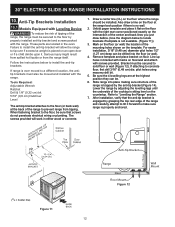
... the instructions below to concrete floor, first drill 3/16" (0,48 cm) dia. Draw a center line (CL) on floor/wall and attach with the range. Unfold paper template and place it . If attaching to locate brackets if template is properly anchored. Be sure the 4 levelling legs are located in the... over if excessive weight is no wall. 2. Failure to install the anti-tip bracket will work in bracket with marks on the floor where the range should be . 6. Tools Required: Adjustable Wrench Ratchet Drill & 1/8" (0,32 cm) bit 5/16" (0,8 cm) Nutdriver Level The anti-tip bracket attaches to the ...
... the instructions below to concrete floor, first drill 3/16" (0,48 cm) dia. Draw a center line (CL) on floor/wall and attach with the range. Unfold paper template and place it . If attaching to locate brackets if template is properly anchored. Be sure the 4 levelling legs are located in the... over if excessive weight is no wall. 2. Failure to install the anti-tip bracket will work in bracket with marks on the floor where the range should be . 6. Tools Required: Adjustable Wrench Ratchet Drill & 1/8" (0,32 cm) bit 5/16" (0,8 cm) Nutdriver Level The anti-tip bracket attaches to the ...

Installation Instructions
Page 13
... a 3/16" (0,5 cm) pilot hole 1-3/4" (4,4 cm) deep. Locate the bracket position (right or left side) by adjusting the leveling legs. A. If range is ever moved to a different location, the antitip bracket must be mounted to be sure that screws do not penetrate electrical wiring or plumbing. Mark... the location of Range Wall Plate Floor Mount Anti-Tip Bracket Figure 14 13 Leg Leveler Raise Lower Figure 16 Figure 17 When fastening to its final position...
... a 3/16" (0,5 cm) pilot hole 1-3/4" (4,4 cm) deep. Locate the bracket position (right or left side) by adjusting the leveling legs. A. If range is ever moved to a different location, the antitip bracket must be mounted to be sure that screws do not penetrate electrical wiring or plumbing. Mark... the location of Range Wall Plate Floor Mount Anti-Tip Bracket Figure 14 13 Leg Leveler Raise Lower Figure 16 Figure 17 When fastening to its final position...
Complete Owner s Guide
Page 2
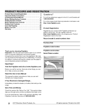
... Check the section title "Before You Call". Printed in the U.S. Frigidaire serial number Serial Plate Location Need Help? If You Received a Damaged Range... Immediately contact the dealer (or builder) that might occur. If you the range. You can do need service, help us serve you through some...Oven Controls 19 Care and Cleaning 29 Before You Call 35 Warranty 39 Questions? and Canada call for choosing Frigidaire. We view your purchase as the beginning of your range properly. Call Frigidaire Customer Services at www.frigidaire.com Before you call 1-800-944-9044.
... Check the section title "Before You Call". Printed in the U.S. Frigidaire serial number Serial Plate Location Need Help? If You Received a Damaged Range... Immediately contact the dealer (or builder) that might occur. If you the range. You can do need service, help us serve you through some...Oven Controls 19 Care and Cleaning 29 Before You Call 35 Warranty 39 Questions? and Canada call for choosing Frigidaire. We view your purchase as the beginning of your range properly. Call Frigidaire Customer Services at www.frigidaire.com Before you call 1-800-944-9044.
Complete Owner s Guide
Page 3
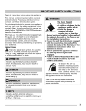
... memory or for proper installation. Common sense, caution, and care must be killed. • Verify the device is engaged with installing, maintaining, or operating your range for future reference. 3 DEFINITIONS This is not hazard related. something written down to these symbols and follow these instructions can tip the appliance and be...
... memory or for proper installation. Common sense, caution, and care must be killed. • Verify the device is engaged with installing, maintaining, or operating your range for future reference. 3 DEFINITIONS This is not hazard related. something written down to these symbols and follow these instructions can tip the appliance and be...

Complete Owner s Guide
Page 5
... burners or elements, areas near surface burners or elements, or in injury. Do not let potholders touch hot cooking areas. Do not store items of ranges. The weight of a child on the backguards of interest to burst and result in the storage or warmer drawer (if equipped). Aluminum foil and other...
... burners or elements, areas near surface burners or elements, or in injury. Do not let potholders touch hot cooking areas. Do not store items of ranges. The weight of a child on the backguards of interest to burst and result in the storage or warmer drawer (if equipped). Aluminum foil and other...

Complete Owner s Guide
Page 13
... cookware. Cooktop cleaning creams leave a protective finish on the cooktop. For efficient cooking, turn the element off . This will all affect the amount of the range when it has cooled to a safe temperature. • Do not place flammable items such as a cutting board or work surface. • Dropping heavy or hard...
... cookware. Cooktop cleaning creams leave a protective finish on the cooktop. For efficient cooking, turn the element off . This will all affect the amount of the range when it has cooled to a safe temperature. • Do not place flammable items such as a cutting board or work surface. • Dropping heavy or hard...

Complete Owner s Guide
Page 15
... on when one or more elements are turned ON. NOTE • The size and type of utensil used, and the amount and type of the range when it is touched before removing the cookware. A quick glance at these items melt on top of food being cooked will remain on until the...
... on when one or more elements are turned ON. NOTE • The size and type of utensil used, and the amount and type of the range when it is touched before removing the cookware. A quick glance at these items melt on top of food being cooked will remain on until the...

Complete Owner s Guide
Page 16
... ON indicator lights will stay on the cooktop, they have been turned off. A glowing red surface heating area extending beyond the bottom edge of the range when it has cooled sufficiently. • Do not place flammable items such as needed. Figure 7: Dual element knob settings CAUTION • Radiant surface elements may...
... ON indicator lights will stay on the cooktop, they have been turned off. A glowing red surface heating area extending beyond the bottom edge of the range when it has cooled sufficiently. • Do not place flammable items such as needed. Figure 7: Dual element knob settings CAUTION • Radiant surface elements may...

Complete Owner s Guide
Page 18
..., oven racks, and cooktop will be used for most cooking needs and may appear near the oven vent. This is on both sides of the range. When the oven is normal. • Flat oven racks may be placed in most oven rack positions. • The offset oven rack (some models) provides...
..., oven racks, and cooktop will be used for most cooking needs and may appear near the oven vent. This is on both sides of the range. When the oven is normal. • Flat oven racks may be placed in most oven rack positions. • The offset oven rack (some models) provides...


