Installation Instructions
Page 1
All about the Installation of your Split Type Room Air Conditioner Refer to Page 2 for table of contents. 2020323B2335 (June 2009) www.frigidaire.com USA 1-866-942-1567 www.frigidaire.ca Canada 1-866-942-1567
All about the Installation of your Split Type Room Air Conditioner Refer to Page 2 for table of contents. 2020323B2335 (June 2009) www.frigidaire.com USA 1-866-942-1567 www.frigidaire.ca Canada 1-866-942-1567

Installation Instructions
Page 2
... of your new air conditioner and thank you for choosing Frigidaire. It is not recommended for heavy commercial or industrial use only. Please refer to the information related to the model you need to dispose of this manual for future reference. We hope you will enjoy your domestic garbage. Attention!! This manual contains all of the instructions before using the air conditioner and keep...
... of your new air conditioner and thank you for choosing Frigidaire. It is not recommended for heavy commercial or industrial use only. Please refer to the information related to the model you need to dispose of this manual for future reference. We hope you will enjoy your domestic garbage. Attention!! This manual contains all of the instructions before using the air conditioner and keep...
Installation Instructions
Page 3
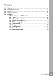
Environmental advices 01 03. Installation: 5.1 Choosing the installation site 04 5.2 Parts list 06 5.3 Indoor unit installation 08 5.4 Outdoor unit installation 12 5.5 Refrigerant piping connection 14 5.6 Electrical work 16 5.7 Purging the system 20 5.8 Electrical safety 23 5.9 Gas leak check 23 5.10 Initial operation test 24 Contents 02 Safety precautions 03 05. Contents 01. Contents 02 04. Welcome 01 02.
Environmental advices 01 03. Installation: 5.1 Choosing the installation site 04 5.2 Parts list 06 5.3 Indoor unit installation 08 5.4 Outdoor unit installation 12 5.5 Refrigerant piping connection 14 5.6 Electrical work 16 5.7 Purging the system 20 5.8 Electrical safety 23 5.9 Gas leak check 23 5.10 Initial operation test 24 Contents 02 Safety precautions 03 05. Contents 01. Contents 02 04. Welcome 01 02.
Installation Instructions
Page 4
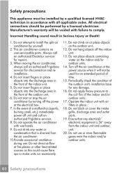
... of the indoor unit. 5. Do not start or stop the air conditioner by a licensed electrician. Turn off the power at the electrical box. 7. Operate the indoor unit with failure to comply. This air conditioner contains no user-serviceable parts. In the event of a malfunction (sparks, burning smell, etc.) immediately power off the indoor unit. 13. Do not hang objects off unit and call an authorized Frigidaire servicer for repairs. 3. Do not use . All electrical connections should...
... of the indoor unit. 5. Do not start or stop the air conditioner by a licensed electrician. Turn off the power at the electrical box. 7. Operate the indoor unit with failure to comply. This air conditioner contains no user-serviceable parts. In the event of a malfunction (sparks, burning smell, etc.) immediately power off the indoor unit. 13. Do not hang objects off unit and call an authorized Frigidaire servicer for repairs. 3. Do not use . All electrical connections should...

Installation Instructions
Page 5
.... 3. Sites with machine oil. 2. Sites with all applicable codes. Carefully read the installation manual before beginning. 2. This appliance must inevitably install the unit at the following sites may cause problems. If you must be performed by a qualified licensed HVAC technician in a void of the manufacturer's warranty. 4. Observe all safety notices. All electrical connections should be installed by a licensed electrician. Failure...
.... 3. Sites with machine oil. 2. Sites with all applicable codes. Carefully read the installation manual before beginning. 2. This appliance must inevitably install the unit at the following sites may cause problems. If you must be performed by a qualified licensed HVAC technician in a void of the manufacturer's warranty. 4. Observe all safety notices. All electrical connections should be installed by a licensed electrician. Failure...
Installation Instructions
Page 6
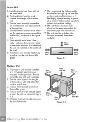
... than 6" Outdoor Unit 1. The site must support the weight of the wall. 6. We recommend the indoor unit to be installed at a location protected from direct sunlight. The site must provide enough space around the indoor unit, as possible on the inside wall (minimum of 7 feet high), always leaving a space of at least 3 feet (1 meter) between the top of the connector pipe and drain hose. 9. The indoor unit must...
... than 6" Outdoor Unit 1. The site must support the weight of the wall. 6. We recommend the indoor unit to be installed at a location protected from direct sunlight. The site must provide enough space around the indoor unit, as possible on the inside wall (minimum of 7 feet high), always leaving a space of at least 3 feet (1 meter) between the top of the connector pipe and drain hose. 9. The indoor unit must...
Installation Instructions
Page 7
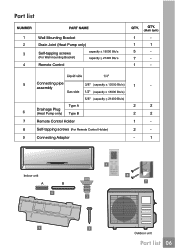
Part list Wall Mounting Bracket Drain Joint (Heat Pump only) Self-tapping screws (For Wall mounting Bracket) Remote Control 21400 Connecting pipe assembly Drainage Plug (Heat Pump only) Type A Type B 21400 Remote Control Holder Self-tapping screws (For Remote Control Holder) Connecting Adaptor (Multi Split) 1 - 1 1 5 - 7 - 1 - 1 - 2 2 2 2 1 - 2 - - 1 A B Part list 06
Part list Wall Mounting Bracket Drain Joint (Heat Pump only) Self-tapping screws (For Wall mounting Bracket) Remote Control 21400 Connecting pipe assembly Drainage Plug (Heat Pump only) Type A Type B 21400 Remote Control Holder Self-tapping screws (For Remote Control Holder) Connecting Adaptor (Multi Split) 1 - 1 1 5 - 7 - 1 - 1 - 2 2 2 2 1 - 2 - - 1 A B Part list 06
Installation Instructions
Page 10
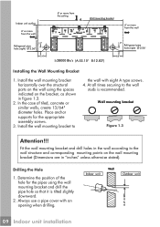
... and corresponding mounting points on the wall using the wall mounting bracket and drill the pipe hole so that it is recommended. Determine the position of tiled, concrete or similar walls, create 13/64" diameter holes. Indoor unit Wall Outdoor unit 09 Indoor unit installation Always use a pipe cover with eight A type screws. 4. Drilling the Hole 1. Install the wall mounting bracket horizontally over the structural parts on the wall mounting bracket (Dimensions are in figure 1.3. 2. Install the wall mounting bracket to the wall with an opening when drilling...
... and corresponding mounting points on the wall using the wall mounting bracket and drill the pipe hole so that it is recommended. Determine the position of tiled, concrete or similar walls, create 13/64" diameter holes. Indoor unit Wall Outdoor unit 09 Indoor unit installation Always use a pipe cover with eight A type screws. 4. Drilling the Hole 1. Install the wall mounting bracket horizontally over the structural parts on the wall mounting bracket (Dimensions are in figure 1.3. 2. Install the wall mounting bracket to the wall with an opening when drilling...

Installation Instructions
Page 11
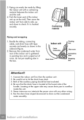
... the air conditioner to see that it may be laid at the back of the indoor unit on the upper hook of the wall mounting bracket, move the indoor unit from the side panel. Pipe cover (right) Pipe holder Pipe cover (left) Left piping Right piping Rear right piping Figure 1.4 Rear left -hand and right-hand piping, remove the pipe cover from side to side to any other place. 2. Do not install the drain hose...
... the air conditioner to see that it may be laid at the back of the indoor unit on the upper hook of the wall mounting bracket, move the indoor unit from the side panel. Pipe cover (right) Pipe holder Pipe cover (left) Left piping Right piping Rear right piping Figure 1.4 Rear left -hand and right-hand piping, remove the pipe cover from side to side to any other place. 2. Do not install the drain hose...
Installation Instructions
Page 12
... careful not to overflow inside the unit. 5. 3. Connect the indoor unit first, then the outdoor unit. 2. Locating at the lowest side of the bundle. Both of room, do not put anything else in the sideward figure. 2. Never intercross nor intertwist the power wire with any other wiring. 6. Because the condensed water from side to side, up and down to drain out the condensed water smoothly. 11 Indoor unit installation
... careful not to overflow inside the unit. 5. 3. Connect the indoor unit first, then the outdoor unit. 2. Locating at the lowest side of the bundle. Both of room, do not put anything else in the sideward figure. 2. Never intercross nor intertwist the power wire with any other wiring. 6. Because the condensed water from side to side, up and down to drain out the condensed water smoothly. 11 Indoor unit installation

Installation Instructions
Page 13
... mount with a bolt and nut 2/5" or 5/16" diameter (Purchased separately). If the installation site is exposed to heavy winds, such as possible, especially in coastal areas, place the unit along the widest part of outdoor unit. A condenser pad is no obstacle which blocks exhausting air, including schrubs or bushes. Direct the air vent toward an area without obstacles. 3. Air inlet Air inlet Air outlet Capacity (BTU...
... mount with a bolt and nut 2/5" or 5/16" diameter (Purchased separately). If the installation site is exposed to heavy winds, such as possible, especially in coastal areas, place the unit along the widest part of outdoor unit. A condenser pad is no obstacle which blocks exhausting air, including schrubs or bushes. Direct the air vent toward an area without obstacles. 3. Air inlet Air inlet Air outlet Capacity (BTU...

Installation Instructions
Page 17
... requirements in table 2.1. 3. If there is a ground wire. (Canadian Electrical Code) for the indoor unit as well as the communication signal and ground between the outdoor and indoor unit. Capacity (BTU/h) System Voltage Volts-Ph.- Fuse/Circuit Breaker Amps(MOP) 15 15 20 25 30 40 35 35 Connecting (Power and Control Cable) cable from the outdoor unit to the client until the problem is grounded well. 5. Electrical work 16
... requirements in table 2.1. 3. If there is a ground wire. (Canadian Electrical Code) for the indoor unit as well as the communication signal and ground between the outdoor and indoor unit. Capacity (BTU/h) System Voltage Volts-Ph.- Fuse/Circuit Breaker Amps(MOP) 15 15 20 25 30 40 35 35 Connecting (Power and Control Cable) cable from the outdoor unit to the client until the problem is grounded well. 5. Electrical work 16
Installation Instructions
Page 18
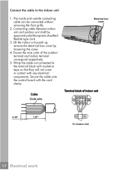
... come in contact with the cord clamp. The inside and outside connecting cable can be approved polychloroprene sheathed flexible type cord. 3. Connecting cable between indoor unit and outdoor unit shall be connected without removing the front grille. 2. Secure the cable onto the control board with any electrical components. Ensure the wire color of indoor unit N(1) 2 3 0.39" 1.57" To Outdoor Unit 17 Electrical work Cable Code wire Electrical box cover Terminal block of the outdoor terminal and indoor...
... come in contact with the cord clamp. The inside and outside connecting cable can be approved polychloroprene sheathed flexible type cord. 3. Connecting cable between indoor unit and outdoor unit shall be connected without removing the front grille. 2. Secure the cable onto the control board with any electrical components. Ensure the wire color of indoor unit N(1) 2 3 0.39" 1.57" To Outdoor Unit 17 Electrical work Cable Code wire Electrical box cover Terminal block of the outdoor terminal and indoor...
Installation Instructions
Page 19
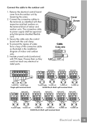
... Btu/h Multi split terminal block Indoor unit A Indoor unit B Indoor unit C Indoor unit D Indoor unit E L1 L2 33400 Btu/h Multi split terminal block Electrical work 18 Connect the cable to power supply shall be approved polychloroprene sheathed flexible cord. 3. The connective cable to the outdoor unit 1. Process them so they could not touch any electrical or metal parts. Connect the connective cables to the terminals as illustrated in the installation diagram of indoor and outdoor units. Remove the electrical control board cover...
... Btu/h Multi split terminal block Indoor unit A Indoor unit B Indoor unit C Indoor unit D Indoor unit E L1 L2 33400 Btu/h Multi split terminal block Electrical work 18 Connect the cable to power supply shall be approved polychloroprene sheathed flexible cord. 3. The connective cable to the outdoor unit 1. Process them so they could not touch any electrical or metal parts. Connect the connective cables to the terminals as illustrated in the installation diagram of indoor and outdoor units. Remove the electrical control board cover...

Installation Instructions
Page 20
... wiring and have an air gap contact separation of at more than 90 percent of the rated voltage marked on the inside of control cover. 2. Cooling or heating (only for disconnection from a power supply shall be evacuated to remove any noncondensables and moisture from vibrations to that the cable thickness is sufficient. 5. Water may freeze and block capillary tubing. 5. Therefore, the indoor unit...
... wiring and have an air gap contact separation of at more than 90 percent of the rated voltage marked on the inside of control cover. 2. Cooling or heating (only for disconnection from a power supply shall be evacuated to remove any noncondensables and moisture from vibrations to that the cable thickness is sufficient. 5. Water may freeze and block capillary tubing. 5. Therefore, the indoor unit...
Installation Instructions
Page 21
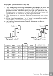
... Additional amount of refrigerant to another place, perform evacuation using vacuum pump. 3. Check that both liquid and gas side tubes) between the indoor and outdoor units have been properly connected and all wiring for single split type air conditioner. (see tabel 2.2) Outdoor unit (A) (B) Outdoor unit (A) Oil trap (B) Indoor unit Piping length under 16' Indoor unit Piping length 16' or more Table 2.2 Cooling capacity (BTU/h) System 9000 Heat Pump 12000 Heat Pump 18000 Cooling Only 18000 Heat Pump Connective pipe Max height length...
... Additional amount of refrigerant to another place, perform evacuation using vacuum pump. 3. Check that both liquid and gas side tubes) between the indoor and outdoor units have been properly connected and all wiring for single split type air conditioner. (see tabel 2.2) Outdoor unit (A) (B) Outdoor unit (A) Oil trap (B) Indoor unit Piping length under 16' Indoor unit Piping length 16' or more Table 2.2 Cooling capacity (BTU/h) System 9000 Heat Pump 12000 Heat Pump 18000 Cooling Only 18000 Heat Pump Connective pipe Max height length...
Installation Instructions
Page 22
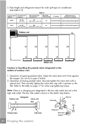
... on page 17 for multi split type air conditioner. (see tabel 2.3) Table 2.3 Cooling capacity Connective pipe (BTU/h) length (Lx) Max connective pipe total length (H1) Max height difference (H2) Air purging Additional amount of closing packed valve: Securely tighten the valve stem with a spanner or the like. Refer to open it hits against the stopper. Operation of refrigerant to be charged 26000...
... on page 17 for multi split type air conditioner. (see tabel 2.3) Table 2.3 Cooling capacity Connective pipe (BTU/h) length (Lx) Max connective pipe total length (H1) Max height difference (H2) Air purging Additional amount of closing packed valve: Securely tighten the valve stem with a spanner or the like. Refer to open it hits against the stopper. Operation of refrigerant to be charged 26000...
Installation Instructions
Page 23
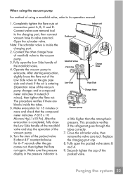
... refrigerant goes through the tubes correctly. 7. Note: The schrader valve is Outdoor unit Indoor unit Manifold Valve -76cm/Hg Charge Hose Low Side High Side Charge Hose Vacuum pump a little higher than the atmospheric pressure. Fully open the packed valve stems B and A. 9. Make sure the pressure display in the pressure indicator is inside the tubes. 5. Purging the system 22 Operate the vacuum pump...
... refrigerant goes through the tubes correctly. 7. Note: The schrader valve is Outdoor unit Indoor unit Manifold Valve -76cm/Hg Charge Hose Low Side High Side Charge Hose Vacuum pump a little higher than the atmospheric pressure. Fully open the packed valve stems B and A. 9. Make sure the pressure display in the pressure indicator is inside the tubes. 5. Purging the system 22 Operate the vacuum pump...
Installation Instructions
Page 24
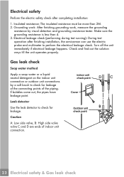
... water or a liquid neutral detergent on the indoor unit connection or outdoor unit connections by visual detection and grounding resistance tester. indoor unit check point Cover Outdoor unit check point 23 Electrical safety & Gas leak check Grounding work: After finishing grounding work, measure the grounding resistance by a soft brush to check for leakage. Make sure the grounding resistance is less than 2M. 2. Leak detector Use the leak...
... water or a liquid neutral detergent on the indoor unit connection or outdoor unit connections by visual detection and grounding resistance tester. indoor unit check point Cover Outdoor unit check point 23 Electrical safety & Gas leak check Grounding work: After finishing grounding work, measure the grounding resistance by a soft brush to check for leakage. Make sure the grounding resistance is less than 2M. 2. Leak detector Use the leak...

Installation Instructions
Page 25
... models with heating function), AUTO and FAN to run in cooling mode, manual operation can be taken. Manual operation is used only when the remote controller is too low(lower than 63 oF), the unit cannot be controlled by the remote controller to check if all the functions work well. 3. Connect the power, press the ON/OFF button on the remote controller to turn the unit on. 2. Initial operation test Perform test operation after completing gas leak...
... models with heating function), AUTO and FAN to run in cooling mode, manual operation can be taken. Manual operation is used only when the remote controller is too low(lower than 63 oF), the unit cannot be controlled by the remote controller to check if all the functions work well. 3. Connect the power, press the ON/OFF button on the remote controller to turn the unit on. 2. Initial operation test Perform test operation after completing gas leak...


