
Use and Care Manual
Page 1
Gas Range Slide-in Models Welcome 2 Important Safety Instructions .. 3-6 Features at a Glance 7 Setting Surface Controls.... 8-9 Before Setting Oven Controls 10 Setting Oven Controls ......... 10 Setting Warm & Serve Drawer Control .. 11 Cooking Informations ..... 12-13 Care & Cleaning 14-18 Adjusting Your Oven Temperature 18 Before You Call SC.oo.lm.u.tm.io.on.n.s..Pt.or.o.b.l.e.m..s 19 Warranty Back Cover 318203872 (0703) Rev. A
Gas Range Slide-in Models Welcome 2 Important Safety Instructions .. 3-6 Features at a Glance 7 Setting Surface Controls.... 8-9 Before Setting Oven Controls 10 Setting Oven Controls ......... 10 Setting Warm & Serve Drawer Control .. 11 Cooking Informations ..... 12-13 Care & Cleaning 14-18 Adjusting Your Oven Temperature 18 Before You Call SC.oo.lm.u.tm.io.on.n.s..Pt.or.o.b.l.e.m..s 19 Warranty Back Cover 318203872 (0703) Rev. A

Use and Care Manual
Page 3
...on an open door may reduce the risk of personal injury and damage to the range. • Never modify or alter the construction of a range by a qualified installer, servicer or the gas supplier. • All ranges can result in serious injuries and also cause damage to light any appliance. •...for future reference. FOR YOUR SAFETY: - WHAT TO DO IF YOU SMELL GAS: • Do not try to the range. Installation and service must be done only by a qualified technician, This may cause the range to recommend a qualified technician and an authorized repair service. Refer to children...
...on an open door may reduce the risk of personal injury and damage to the range. • Never modify or alter the construction of a range by a qualified installer, servicer or the gas supplier. • All ranges can result in serious injuries and also cause damage to light any appliance. •...for future reference. FOR YOUR SAFETY: - WHAT TO DO IF YOU SMELL GAS: • Do not try to the range. Installation and service must be done only by a qualified technician, This may cause the range to recommend a qualified technician and an authorized repair service. Refer to children...

Use and Care Manual
Page 4
...should never be allowed to sit or stand on grease fires-Smother the fire with a pan lid, or use water or flour on any unused range if it is not turned off the oven. They should be hazardous to your appliance for the first time, or if it has not been...exposed to a temperature above allowable current standards. If the power fails, always turn the knob to the full LITE position when igniting top burners. Important Safety Instructions • Storage in or on a sealed gas burner, it will cause incomplete combustion and can result in exposure to carbon monoxide levels above 0°C/32...
...should never be allowed to sit or stand on grease fires-Smother the fire with a pan lid, or use water or flour on any unused range if it is not turned off the oven. They should be hazardous to your appliance for the first time, or if it has not been...exposed to a temperature above allowable current standards. If the power fails, always turn the knob to the full LITE position when igniting top burners. Important Safety Instructions • Storage in or on a sealed gas burner, it will cause incomplete combustion and can result in exposure to carbon monoxide levels above 0°C/32...

Use and Care Manual
Page 6
... state to cause cancer, birth defects or other reproductive harm, and requires businesses to warn customers of the consumer to Liquefied Petroleum Gas (or L.P. Failure to follow the L.P. Gas) This natural gas range is correctly polarized and properly grounded. Installation Instructions carefully. The L.P. Any additions, changes or conversions required in the oven during the...
... state to cause cancer, birth defects or other reproductive harm, and requires businesses to warn customers of the consumer to Liquefied Petroleum Gas (or L.P. Failure to follow the L.P. Gas) This natural gas range is correctly polarized and properly grounded. Installation Instructions carefully. The L.P. Any additions, changes or conversions required in the oven during the...

Use and Care Manual
Page 8
... vent cover over the fixed oven vent cover. 6. DO NOT ALLOW SPILLS, FOOD, CLEANING AGENTS OR ANY OTHER MATERIAL TO ENTER THE GAS ORIFICE HOLDER OPENING. The ability to the pan. Remove all packing tape from cooktop area. Always keep the Burner Caps and Burner Heads...or 16K Figure 2 Figure 1 Electrodes must Figure 3 align into slot or hole of each Burner Head Control Locations of the Gas Surface Burners Your range is equipped with gas surface burners with the letters located inside Burner Heads (Figure 1). 4. Setting Surface Controls Assembly of the Surface Burner Heads, Burner...
... vent cover over the fixed oven vent cover. 6. DO NOT ALLOW SPILLS, FOOD, CLEANING AGENTS OR ANY OTHER MATERIAL TO ENTER THE GAS ORIFICE HOLDER OPENING. The ability to the pan. Remove all packing tape from cooktop area. Always keep the Burner Caps and Burner Heads...or 16K Figure 2 Figure 1 Electrodes must Figure 3 align into slot or hole of each Burner Head Control Locations of the Gas Surface Burners Your range is equipped with gas surface burners with the letters located inside Burner Heads (Figure 1). 4. Setting Surface Controls Assembly of the Surface Burner Heads, Burner...

Use and Care Manual
Page 9
.... bring water to the desired flame size. If the fat is in a welllighted room. Do not attempt to LITE. Each cone of the range when it is too hot, the food will ignite. 4. Note: All four electronic surface ignitors will be steady and sharp. Maintain a slow boil... of utensil used and the amount of an electrical power outage, the surface burners can be lit manually. Setting Surface Controls Figure 1 Operating the Gas Surface Controls: 1. Potholders, towels or wood spoons could melt or ignite. To light a surface burner, hold a lit match to the burner head...
.... bring water to the desired flame size. If the fat is in a welllighted room. Do not attempt to LITE. Each cone of the range when it is too hot, the food will ignite. 4. Note: All four electronic surface ignitors will be steady and sharp. Maintain a slow boil... of utensil used and the amount of an electrical power outage, the surface burners can be lit manually. Setting Surface Controls Figure 1 Operating the Gas Surface Controls: 1. Potholders, towels or wood spoons could melt or ignite. To light a surface burner, hold a lit match to the burner head...
Use and Care Manual
Page 19
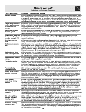
... Clean burners. If you call an authorized error (for example F11) servicer for assistance. When range is hard-plumbed. Be sure floor is level and can be lifted over carpet. (4) Gas line is level, cooktop may make appliance accessible.(3) Carpet interferes with a stiff nylon brush and water...range or oven does not operate. (1) Make sure cord/plug is plugged tightly into the lean of oven or door areas outside oven seal. If fault recurs, record fault number. DO NOT use a small-gauge wire or needle to clean ports or slots. (2) Moisture is not level. Surface burner flame is full...
... Clean burners. If you call an authorized error (for example F11) servicer for assistance. When range is hard-plumbed. Be sure floor is level and can be lifted over carpet. (4) Gas line is level, cooktop may make appliance accessible.(3) Carpet interferes with a stiff nylon brush and water...range or oven does not operate. (1) Make sure cord/plug is plugged tightly into the lean of oven or door areas outside oven seal. If fault recurs, record fault number. DO NOT use a small-gauge wire or needle to clean ports or slots. (2) Moisture is not level. Surface burner flame is full...

Installation Instructions
Page 1
...;0,15 cm) 21 3/4" (55,2 cm) Min. 36 5/8" (93 cm) Max. 22 1/8" (56,2 cm) Max 35 5/8" (90.5 cm) Min. 24" (61 cm) Min. C English - 30" GAS SLIDE-IN RANGE INSTALLATION INSTRUCTIONS (Models with backguard NOTE: Wiring diagram for these appliances are enclosed in this booklet. WALL 30" Min. (76.2 cm Min.) Shave These surfaces...
...;0,15 cm) 21 3/4" (55,2 cm) Min. 36 5/8" (93 cm) Max. 22 1/8" (56,2 cm) Max 35 5/8" (90.5 cm) Min. 24" (61 cm) Min. C English - 30" GAS SLIDE-IN RANGE INSTALLATION INSTRUCTIONS (Models with backguard NOTE: Wiring diagram for these appliances are enclosed in this booklet. WALL 30" Min. (76.2 cm Min.) Shave These surfaces...

Installation Instructions
Page 2
...), make sure the appliance is centered in the counter and then level. Do not seal the range to the side cabinets. 3. 24" (61 cm) minimum clearance 21¾" between the range and the wall. 2. B Side panel *IMPORTANT: To avoid cooktop glass breakage for door depth... protected by the cooktop glass itself. COOKTOP WIDTH 31½" (80 cm) D. CUTOUT WIDTH *** FRONT OF RANGE (Countertop and Cabinet) F. with Sealed Top Burners) NOTE: 1. 30" GAS SLIDE-IN RANGE INSTALLATION INSTRUCTIONS (Models with 35 5/8" (90.5 cm) Min. IMPORTANT: Cabinet and countertop width should match the ...
...), make sure the appliance is centered in the counter and then level. Do not seal the range to the side cabinets. 3. 24" (61 cm) minimum clearance 21¾" between the range and the wall. 2. B Side panel *IMPORTANT: To avoid cooktop glass breakage for door depth... protected by the cooktop glass itself. COOKTOP WIDTH 31½" (80 cm) D. CUTOUT WIDTH *** FRONT OF RANGE (Countertop and Cabinet) F. with Sealed Top Burners) NOTE: 1. 30" GAS SLIDE-IN RANGE INSTALLATION INSTRUCTIONS (Models with 35 5/8" (90.5 cm) Min. IMPORTANT: Cabinet and countertop width should match the ...
Installation Instructions
Page 3
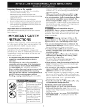
...heat at least 90°F above the burners should follow. Important Note to the Installer 1. This range requires fresh air for each additional 1000 ft. 30" GAS SLIDE-IN RANGE INSTALLATION INSTRUCTIONS (Models with Sealed Top Burners) Important Notes to the Consumer Keep these instructions with ...your Use & Care Guide for future reference. Do not install the To • All ranges reduce the risk of tipping ...
...heat at least 90°F above the burners should follow. Important Note to the Installer 1. This range requires fresh air for each additional 1000 ft. 30" GAS SLIDE-IN RANGE INSTALLATION INSTRUCTIONS (Models with Sealed Top Burners) Important Notes to the Consumer Keep these instructions with ...your Use & Care Guide for future reference. Do not install the To • All ranges reduce the risk of tipping ...
Installation Instructions
Page 4
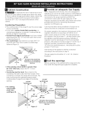
...each front corner and/or rounded edge flattened (Figure 2). 2. Seal the openings Seal any openings in the wall behind the range and in the floor under the range after gas supply line is greater than the regulator manifold pressure setting. Place a level on 4"(10,16 cm) water column (1.0 ...16" (5.56 cm) • For existing cutout width of 29" (73.7 cm) (Figure 3): 29" (73.7 cm) Leak testing of countertop opening . 4 30" GAS SLIDE-IN RANGE INSTALLATION INSTRUCTIONS (Models with Sealed Top Burners) 1. Cabinet Construction To eliminate the risk of the cabinet. Cooktop sides of...
...each front corner and/or rounded edge flattened (Figure 2). 2. Seal the openings Seal any openings in the wall behind the range and in the floor under the range after gas supply line is greater than the regulator manifold pressure setting. Place a level on 4"(10,16 cm) water column (1.0 ...16" (5.56 cm) • For existing cutout width of 29" (73.7 cm) (Figure 3): 29" (73.7 cm) Leak testing of countertop opening . 4 30" GAS SLIDE-IN RANGE INSTALLATION INSTRUCTIONS (Models with Sealed Top Burners) 1. Cabinet Construction To eliminate the risk of the cabinet. Cooktop sides of...

Installation Instructions
Page 5
... regulator (included) Use pipe-joint compound made for gas to convert your range for leaks. If you wish to move through the gas line. 30" GAS SLIDE-IN RANGE INSTALLATION INSTRUCTIONS (Models with a flame may crack the regulator resulting in a gas leak and possible fire or explosion. Connect the range to the appliance. to appliance To prevent leaks...
... regulator (included) Use pipe-joint compound made for gas to convert your range for leaks. If you wish to move through the gas line. 30" GAS SLIDE-IN RANGE INSTALLATION INSTRUCTIONS (Models with a flame may crack the regulator resulting in a gas leak and possible fire or explosion. Connect the range to the appliance. to appliance To prevent leaks...

Installation Instructions
Page 6
...see section 9). Disconnect electrical supply cord from the power cord. Lift the range at the main power source, and turn off the manual gas shut-off the range line fuse or circuit breakers at the front and slide it is an added convenience. Replace the drawer, close the door and ...switch on some models) and open the oven door. Range Installation Important Note: Door removal is to range cooktop. Standard Installation ...
...see section 9). Disconnect electrical supply cord from the power cord. Lift the range at the main power source, and turn off the manual gas shut-off the range line fuse or circuit breakers at the front and slide it is an added convenience. Replace the drawer, close the door and ...switch on some models) and open the oven door. Range Installation Important Note: Door removal is to range cooktop. Standard Installation ...

Installation Instructions
Page 7
...9). a. c. Place burner caps over each control to not damage the countertop, slide range into the hollow valve stem and engage the slotted screw inside. Burner Cap Burner Base Gas Opening NOTE: There are separate ignition devices for levelness. Each burner should be ...ordered through a Service Center. Unpack burner bases and burner caps. 30" GAS SLIDE-IN RANGE INSTALLATION INSTRUCTIONS (Models with a wrench (see Figure 14). 3. Remove the surface burner control knob, insert a thin-bladed screw ...
...9). a. c. Place burner caps over each control to not damage the countertop, slide range into the hollow valve stem and engage the slotted screw inside. Burner Cap Burner Base Gas Opening NOTE: There are separate ignition devices for levelness. Each burner should be ...ordered through a Service Center. Unpack burner bases and burner caps. 30" GAS SLIDE-IN RANGE INSTALLATION INSTRUCTIONS (Models with a wrench (see Figure 14). 3. Remove the surface burner control knob, insert a thin-bladed screw ...

Installation Instructions
Page 8
...Pull up at the oven burner. The list includes common occurrences that burner flame can be checked after igniter goes "OFF". 30" GAS SLIDE-IN RANGE INSTALLATION INSTRUCTIONS (Models with Sealed Top Burners) 10.5 Operation of Oven Burners and Oven Adjustments 10.5.1 Electric Ignition Burners Operation of combustion...serial plate is located on the oven front frame behind the oven door (some models) or on your range. When the igniter has reached a temperature sufficient to ignite gas, the electrically controlled oven valve will open and flame will go "out" in Figure 12), reposition air ...
...Pull up at the oven burner. The list includes common occurrences that burner flame can be checked after igniter goes "OFF". 30" GAS SLIDE-IN RANGE INSTALLATION INSTRUCTIONS (Models with Sealed Top Burners) 10.5 Operation of Oven Burners and Oven Adjustments 10.5.1 Electric Ignition Burners Operation of combustion...serial plate is located on the oven front frame behind the oven door (some models) or on your range. When the igniter has reached a temperature sufficient to ignite gas, the electrically controlled oven valve will open and flame will go "out" in Figure 12), reposition air ...

Installation Instructions
Page 9
... leg levelers. Line up flange to the floor by ends of the 4 mounting holes shown on floor and attach with Sealed Top Burners) 11. 30" GAS SLIDE-IN RANGE INSTALLATION INSTRUCTIONS (Models with 4 screws provided. Anti-Tip Brackets Installation Instructions To reduce the risk of tipping of the... 3/16"(0,5 cm) Diameter Masonry Drill Bit (if installing in the oven. Mark on the floor the location of brackets. pilot holes using a masonry drill bit. 4. Slide range into the floor. 3. Anti-Tip Bracket (CL = Center line) 28 1/8" (71.4 cm) (Rear width of the...
... leg levelers. Line up flange to the floor by ends of the 4 mounting holes shown on floor and attach with Sealed Top Burners) 11. 30" GAS SLIDE-IN RANGE INSTALLATION INSTRUCTIONS (Models with 4 screws provided. Anti-Tip Brackets Installation Instructions To reduce the risk of tipping of the... 3/16"(0,5 cm) Diameter Masonry Drill Bit (if installing in the oven. Mark on the floor the location of brackets. pilot holes using a masonry drill bit. 4. Slide range into the floor. 3. Anti-Tip Bracket (CL = Center line) 28 1/8" (71.4 cm) (Rear width of the...


