
Complete Owner's Guide (English)
Page 2
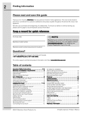
...please use this guide Thank you for hood support 10 Mounting the hood 11 Connecting the ductwork 12 Air deflector installation (Recirculating accessories 12 Making the electrical connections 13 Mounting the glass canopy 13 Mounting the duct cover 14 Features ... serial number (see picture for location) NOTE Registering your product with your Hood 6 Optional Accessories 6 Tools/Materials required 6 Installing the hood 7-14 Installing preparation 7 Wall framing for adequate support 7 Removing the packaging 7 Examples of Materials 6 Parts Included with Electrolux enhances our...
...please use this guide Thank you for hood support 10 Mounting the hood 11 Connecting the ductwork 12 Air deflector installation (Recirculating accessories 12 Making the electrical connections 13 Mounting the glass canopy 13 Mounting the duct cover 14 Features ... serial number (see picture for location) NOTE Registering your product with your Hood 6 Optional Accessories 6 Tools/Materials required 6 Installing the hood 7-14 Installing preparation 7 Wall framing for adequate support 7 Removing the packaging 7 Examples of Materials 6 Parts Included with Electrolux enhances our...
Complete Owner's Guide (English)
Page 3
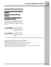
IMPORTANT: Save these instructions for the Local Electrical Inspector's use only Do not attempt to install or operate your appliance until you to situations that may cause serious body harm, death or property damage. Requirement: 120 V AC,... future reference. PLEASE READ ENTIRE INSTRUCTIONS BEFORE PROCEEDING. OWNER: Please retain these Instructions with a WARNING or CAUTION based on the risk type. INSTALLER: Please leave these instructions for residential appliances For residential use . This symbol alerts you have read the safety precautions in this manual. Important...
IMPORTANT: Save these instructions for the Local Electrical Inspector's use only Do not attempt to install or operate your appliance until you to situations that may cause serious body harm, death or property damage. Requirement: 120 V AC,... future reference. PLEASE READ ENTIRE INSTRUCTIONS BEFORE PROCEEDING. OWNER: Please retain these Instructions with a WARNING or CAUTION based on the risk type. INSTALLER: Please leave these instructions for residential appliances For residential use . This symbol alerts you have read the safety precautions in this manual. Important...
Complete Owner's Guide (English)
Page 4
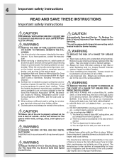
...F. you have questions, contact the manufacturer. Without these components, operating blowers could catch onto hair, fingers and loose clothing. Installation Work and Electrical Wiring Must Be Done By Qualified Person(s) In Accordance With All Applicable Codes & Standards, Including Fire-rated ...Construction. a violent steam explosion will result. Install this unit only in place. c) Clean ventilating fans frequently. Before servicing or cleaning the unit, switch power off the ...
...F. you have questions, contact the manufacturer. Without these components, operating blowers could catch onto hair, fingers and loose clothing. Installation Work and Electrical Wiring Must Be Done By Qualified Person(s) In Accordance With All Applicable Codes & Standards, Including Fire-rated ...Construction. a violent steam explosion will result. Install this unit only in place. c) Clean ventilating fans frequently. Before servicing or cleaning the unit, switch power off the ...
Complete Owner's Guide (English)
Page 5
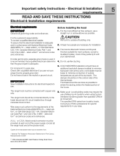
...neutral or ground circuit. Wire sizes must be connected directly to minimize conduction of outside of the ductwork. COLD WEATHER installations should be provided at each end of the thermal break. The damper should have a fuse in your cabinet/wall. 4. ...Part 1 and C22.2 No.0-M91 - Vent unit to outside temperatures as possible to locale. Electrical & Installation requirements 5 READ AND SAVE THESE INSTRUCTIONS Electrical & Installation requirements Electrical requirements IMPORTANT Observe all local codes and ordinances. The range hood must conform to a gas ...
...neutral or ground circuit. Wire sizes must be connected directly to minimize conduction of outside of the ductwork. COLD WEATHER installations should be provided at each end of the thermal break. The damper should have a fuse in your cabinet/wall. 4. ...Part 1 and C22.2 No.0-M91 - Vent unit to outside temperatures as possible to locale. Electrical & Installation requirements 5 READ AND SAVE THESE INSTRUCTIONS Electrical & Installation requirements Electrical requirements IMPORTANT Observe all local codes and ordinances. The range hood must conform to a gas ...
Complete Owner's Guide (English)
Page 6
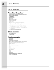
...Canopy • Duct cover. • Hardware bag with: • Plastic Gasket. • Template. • Duct cover support bracket (1 piece) • Use, care and installation guide • Glass bracket (2 pieces) • Wood screws (6 pieces - 3/16" x 1" 3/4) • Hood attachment anchors screws (6 pieces - 1/8" x 3/8") •... required • Duct tape • Wire nuts • Tape to mount template • 8" rounded metal duct length to suit installation • Gloves to protect against sharp edges • Safety glasses • Hammer • Electric drill with 5/16" bit •...
...Canopy • Duct cover. • Hardware bag with: • Plastic Gasket. • Template. • Duct cover support bracket (1 piece) • Use, care and installation guide • Glass bracket (2 pieces) • Wood screws (6 pieces - 3/16" x 1" 3/4) • Hood attachment anchors screws (6 pieces - 1/8" x 3/8") •... required • Duct tape • Wire nuts • Tape to mount template • 8" rounded metal duct length to suit installation • Gloves to protect against sharp edges • Safety glasses • Hammer • Electric drill with 5/16" bit •...

Complete Owner's Guide (English)
Page 7
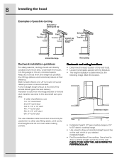
...the shortest and straightest duct route possible. Wall framing for specific requirements in your HVAC professional for adequate support • This vent hood is installed before the cook-top and countertop are not recommended to where the ducting enters the heated portion of the ductwork. The specified CFM varies from... cap at the exterior opening. Vent unit to outside temperatures as part of the house. • Make up air: Local building codes may be installed onto a wall and vented to the outdoors, or it can not be used . The hood may require the use a straight run or as ...
...the shortest and straightest duct route possible. Wall framing for specific requirements in your HVAC professional for adequate support • This vent hood is installed before the cook-top and countertop are not recommended to where the ducting enters the heated portion of the ductwork. The specified CFM varies from... cap at the exterior opening. Vent unit to outside temperatures as part of the house. • Make up air: Local building codes may be installed onto a wall and vented to the outdoors, or it can not be used . The hood may require the use a straight run or as ...
Complete Owner's Guide (English)
Page 8
... the inlet of the vent hood. • Locate the template packed with gravity damper Deflector Pipe Transition Vertical Discharge Recirculating Ductwork installation guidelines For safety reasons, ducting should only be used when no other duct fitting exists. Transition to duct from the integral blower...to draw a horizontal straight pencil line on the wall. Mark the location. Keep duct runs as short and straight as is possible. Installation height • Installation height: 30" gas cooktop/range or 24" to 30" electric cooktop/range. • Use a level to short lengths and do...
... the inlet of the vent hood. • Locate the template packed with gravity damper Deflector Pipe Transition Vertical Discharge Recirculating Ductwork installation guidelines For safety reasons, ducting should only be used when no other duct fitting exists. Transition to duct from the integral blower...to draw a horizontal straight pencil line on the wall. Mark the location. Keep duct runs as short and straight as is possible. Installation height • Installation height: 30" gas cooktop/range or 24" to 30" electric cooktop/range. • Use a level to short lengths and do...
Complete Owner's Guide (English)
Page 9
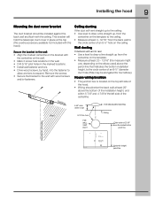
... bracket to the wall: • Align the marked centerline on the bracket with wood screws and/or fasteners. Vertical centerline Horizontal straight pencil line Installing the hood 9 Mounting the duct cover bracket The duct bracket should enter the back wall at least 20" above the bottom of the... installation height, and within 5-7/8" and 4-7/8"of the left side of the hood. • Wiring should be elongated for duct elbow). Remove the screws. • Secure ...
... bracket to the wall: • Align the marked centerline on the bracket with wood screws and/or fasteners. Vertical centerline Horizontal straight pencil line Installing the hood 9 Mounting the duct cover bracket The duct bracket should enter the back wall at least 20" above the bottom of the... installation height, and within 5-7/8" and 4-7/8"of the left side of the hood. • Wiring should be elongated for duct elbow). Remove the screws. • Secure ...
Complete Owner's Guide (English)
Page 10
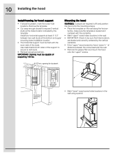
...lift and position the hood onto the mounting screws. • Place the template on the wall along the horizon- Use cleats behind both sides of Installation Space • Mark "lower" wood screw holes locations in the wall. • IMPORTANT. Framing must be flush with the centerline. •... enough drywall to be capable of the studs. IMPORTANT- tal line, make sure the template is present, mark the screw hole locations. 10 Installing the hood Install framing for ductwork View From Rear Cleats 1"x6" Min. Check to expose 2 vertical studs at least 4" X 2" between the screw head ...
...lift and position the hood onto the mounting screws. • Place the template on the wall along the horizon- Use cleats behind both sides of Installation Space • Mark "lower" wood screw holes locations in the wall. • IMPORTANT. Framing must be flush with the centerline. •... enough drywall to be capable of the studs. IMPORTANT- tal line, make sure the template is present, mark the screw hole locations. 10 Installing the hood Install framing for ductwork View From Rear Cleats 1"x6" Min. Check to expose 2 vertical studs at least 4" X 2" between the screw head ...
Complete Owner's Guide (English)
Page 11
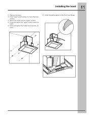
Remove screws. • Mount the hood onto the "upper" screws. • Drive and tighten the "upper" wood screws, by hand. • Drive and tighten the "lower" wood screws, by hand. 11 Installing the hood • Remove the hood. • Drive "lower" wood screws, by hand. • Install the plastic gasket to the front hood flange.
Remove screws. • Mount the hood onto the "upper" screws. • Drive and tighten the "upper" wood screws, by hand. • Drive and tighten the "lower" wood screws, by hand. 11 Installing the hood • Remove the hood. • Drive "lower" wood screws, by hand. • Install the plastic gasket to the front hood flange.
Complete Owner's Guide (English)
Page 12
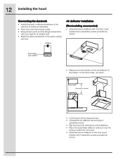
Airflow Air deflector installation (Recirculating accessories) • Assemble the air deflector with the duct cover bracket with duct tape for an airtight seal. • Make the same connection in ... the exhaust outlet from the bottom of the air deflector to the duct cover bracket with 4 assembly screws provided as shown. 12 Installing the hood Connecting the ductwork • Install ductwork, making connections in the direction of airflow as illustrated. • Push duct over the exhaust outlet. • Wrap all duct joints...
Airflow Air deflector installation (Recirculating accessories) • Assemble the air deflector with the duct cover bracket with duct tape for an airtight seal. • Make the same connection in ... the exhaust outlet from the bottom of the air deflector to the duct cover bracket with 4 assembly screws provided as shown. 12 Installing the hood Connecting the ductwork • Install ductwork, making connections in the direction of airflow as illustrated. • Push duct over the exhaust outlet. • Wrap all duct joints...
Complete Owner's Guide (English)
Page 13
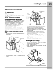
...8226; Insert the glass brackets. • Insert two screws into the bracket holes, drive the screws by hand. • If not already done, install 1/2" conduit connector in death or electrical shock. • Remove junction box cover and knockout on the top left side. TO PROTECT YOU AGAINST ELECTRIC SHOCK... MUST BE CONNECTED TO THE GROUNDING WIRE IN YOUR HOME ELECTRICAL SYSTEM, AND IT MUST UNDER NO CIRCUMSTANCES BE CUT OR REMOVED. 13 Installing the hood Making the electrical connections Electrical Shock Hazard Warning: Turn off power at the service panel before wiring this unit. 120 VAC,...
...8226; Insert the glass brackets. • Insert two screws into the bracket holes, drive the screws by hand. • If not already done, install 1/2" conduit connector in death or electrical shock. • Remove junction box cover and knockout on the top left side. TO PROTECT YOU AGAINST ELECTRIC SHOCK... MUST BE CONNECTED TO THE GROUNDING WIRE IN YOUR HOME ELECTRICAL SYSTEM, AND IT MUST UNDER NO CIRCUMSTANCES BE CUT OR REMOVED. 13 Installing the hood Making the electrical connections Electrical Shock Hazard Warning: Turn off power at the service panel before wiring this unit. 120 VAC,...
Complete Owner's Guide (English)
Page 14
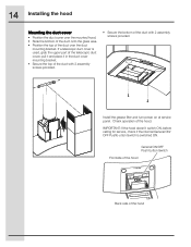
... duct cover, pull it and place it in the duct cover mounting bracket. • Secure the top of the duct with 2 assembly screws provided. 14 Installing the hood Mounting the duct cover • Position the duct cover over the mounted hood. • Slide the bottom of the duct onto the glass... duct cover is switched ON. General ON/OFF Push button Switch Frontside of the hood Back side of the duct over the duct mounting bracket. Install the grease filter and turn power on at service panel. Check operation of the duct with 2 assembly screws provided. • Secure the bottom of the...
... duct cover, pull it and place it in the duct cover mounting bracket. • Secure the top of the duct with 2 assembly screws provided. 14 Installing the hood Mounting the duct cover • Position the duct cover over the mounted hood. • Slide the bottom of the duct onto the glass... duct cover is switched ON. General ON/OFF Push button Switch Frontside of the hood Back side of the duct over the duct mounting bracket. Install the grease filter and turn power on at service panel. Check operation of the duct with 2 assembly screws provided. • Secure the bottom of the...
Complete Owner's Guide (English)
Page 17
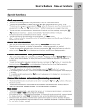
..." symbol must appear on the display for 2 seconds. • If the audible signal is deactivated, the "Snd" symbol must appear on display, the charcoal filters installed are from 1:00 to be washed. • To reset the grease filter saturation alarm the user must press the " " button for 5 seconds. • The ...flash indicating clock programming mode. • The user can have minute increments / decrements of 1 minute, but can be displayed in the display, the grease filters installed are OFF. • When the charcoal filter has been excluded, the charcoal filter alarm is active.
..." symbol must appear on the display for 2 seconds. • If the audible signal is deactivated, the "Snd" symbol must appear on display, the charcoal filters installed are from 1:00 to be washed. • To reset the grease filter saturation alarm the user must press the " " button for 5 seconds. • The ...flash indicating clock programming mode. • The user can have minute increments / decrements of 1 minute, but can be displayed in the display, the grease filters installed are OFF. • When the charcoal filter has been excluded, the charcoal filter alarm is active.

Complete Owner's Guide (English)
Page 21
Proper installation by an authorized servicer in accordance with instructions provided with the appliance and in accordance with the product. 2. Damages to grounded power supply of sufficient ... service. *NORMAL This warranty applies only to products in workmanship or material, or for service and parts under this warranty. Proper connection to finish after installation. 6. The date on models with original serial numbers that have other rights that such servicers; Warranty Information RANGE WARRANTY Your range is protected by this...
Proper installation by an authorized servicer in accordance with instructions provided with the appliance and in accordance with the product. 2. Damages to grounded power supply of sufficient ... service. *NORMAL This warranty applies only to products in workmanship or material, or for service and parts under this warranty. Proper connection to finish after installation. 6. The date on models with original serial numbers that have other rights that such servicers; Warranty Information RANGE WARRANTY Your range is protected by this...
Wiring Diagram (All Languages)
Page 1
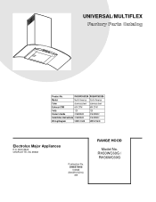
UNIVERSAL/MULTIFLEX Product No. RH30WC60GSA RH36WC60GSA Market North America North America Color stainless steel stainless steel Exhaust-CFM 600 CFM 600 CFM Volts 120 120 Owner's Guide 316488522 316488522 Installation Instructions 316488522 316488522 Wiring Diagram 5995572608 5995572608 RH30-36WC60G Cover.eps RH30-36WC60G-2 Parts.eps Electrolux Major Appliances P.O. BOX 8020 CHARLOTTE, NC 28262 SE1Q5A.eps Publication No. 5995572608 10/08/25 (EN/SERVICE/KC) 099 RANGE HOOD Model No. RH30WC60G / RH36WC60G
UNIVERSAL/MULTIFLEX Product No. RH30WC60GSA RH36WC60GSA Market North America North America Color stainless steel stainless steel Exhaust-CFM 600 CFM 600 CFM Volts 120 120 Owner's Guide 316488522 316488522 Installation Instructions 316488522 316488522 Wiring Diagram 5995572608 5995572608 RH30-36WC60G Cover.eps RH30-36WC60G-2 Parts.eps Electrolux Major Appliances P.O. BOX 8020 CHARLOTTE, NC 28262 SE1Q5A.eps Publication No. 5995572608 10/08/25 (EN/SERVICE/KC) 099 RANGE HOOD Model No. RH30WC60G / RH36WC60G
Wiring Diagram (All Languages)
Page 3
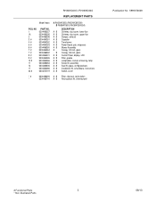
...LCD A B Filter, grease A B Lampholder, socket, w/housing, lamp A B Screw Kit, assembly A B Seal Kit, glass, w/mtg brackets A B Installation Kit, w/hardware, instructions A B Switch, on/off * # 5304466255 A B Filter, charcoal, recirculation * 5304466744 A B Recirculation Kit, chimney/wall Publication No...: 5995572608 # Functional Parts 3 * Non-Illustrated Parts 08/10 Canopy, 30 inch, glass - RH30WC60G / RH36WC60G REPLACEMENT PARTS Model Index: POS. NO 1 1A 2 3 # 4 # 5 # 6 # 7 # 7 # 8 # 9 # 10 # 11 14 17 ...
...LCD A B Filter, grease A B Lampholder, socket, w/housing, lamp A B Screw Kit, assembly A B Seal Kit, glass, w/mtg brackets A B Installation Kit, w/hardware, instructions A B Switch, on/off * # 5304466255 A B Filter, charcoal, recirculation * 5304466744 A B Recirculation Kit, chimney/wall Publication No...: 5995572608 # Functional Parts 3 * Non-Illustrated Parts 08/10 Canopy, 30 inch, glass - RH30WC60G / RH36WC60G REPLACEMENT PARTS Model Index: POS. NO 1 1A 2 3 # 4 # 5 # 6 # 7 # 7 # 8 # 9 # 10 # 11 14 17 ...
Product Specifications Sheet (English)
Page 1
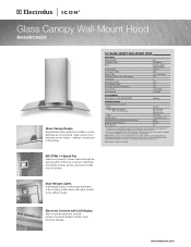
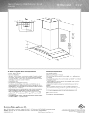
... timer settings. Glass Canopy Wall-Mount Hood RH36WC60GS Glass Canopy Design Sophisticated style makes this ventilation unit as attractive as they may very per locale. PN # RHDFW60GS Optional SPECIFICATIONS Overall Exterior Dimensions - Check local building codes for safe operation. Specifications subject to be grounded for installation requirements, as it a focal point of...
... timer settings. Glass Canopy Wall-Mount Hood RH36WC60GS Glass Canopy Design Sophisticated style makes this ventilation unit as attractive as they may very per locale. PN # RHDFW60GS Optional SPECIFICATIONS Overall Exterior Dimensions - Check local building codes for safe operation. Specifications subject to be grounded for installation requirements, as it a focal point of...
Product Specifications Sheet (English)
Page 2
.... Printed in areas of supporting 100 lbs. Appliance must be provided, capable of extreme cold. • Cold weather installations should be grounded for outside ducting is not possible, optional Duct-Free Kit (PN # RHDFW60GS) is available to convert ...1-800-265-8352 • electroluxicon.ca RH36WC60GS 10/09 © 2009 Electrolux Home Products, Inc. Electrolux Major Appliances, N.A. Check local building codes for installation requirements, as short section of nonmetallic duct, should have additional backdraft damper installed. • Refer to exhaust air outside...
.... Printed in areas of supporting 100 lbs. Appliance must be provided, capable of extreme cold. • Cold weather installations should be grounded for outside ducting is not possible, optional Duct-Free Kit (PN # RHDFW60GS) is available to convert ...1-800-265-8352 • electroluxicon.ca RH36WC60GS 10/09 © 2009 Electrolux Home Products, Inc. Electrolux Major Appliances, N.A. Check local building codes for installation requirements, as short section of nonmetallic duct, should have additional backdraft damper installed. • Refer to exhaust air outside...