

Operator Manual
Page 5
... has been tested and found to comply with the instruction manual, may cause harmful interference to radio communications. However, there is no guarantee that to Part 15 of the following measures: • Reorient or relocate the receiving antenna. • Increase the separation between the equipment and receiver. • Connect the equipment...
... has been tested and found to comply with the instruction manual, may cause harmful interference to radio communications. However, there is no guarantee that to Part 15 of the following measures: • Reorient or relocate the receiving antenna. • Increase the separation between the equipment and receiver. • Connect the equipment...

Operator Manual
Page 9
... domestic applications, or in scanner parts. cannot be conducted as required by local ordinances or regulations. Too avoid unexpected injury, read the followings carefully. Dispose of mercury Scanner lamp includes mercury. About the use of the scanner should be reproduced without the... permission of bank notes, currency, government-issued bonds and passports, licenses and permits issued by public and private organizations, official documents, private documents, etc.
... domestic applications, or in scanner parts. cannot be conducted as required by local ordinances or regulations. Too avoid unexpected injury, read the followings carefully. Dispose of mercury Scanner lamp includes mercury. About the use of the scanner should be reproduced without the... permission of bank notes, currency, government-issued bonds and passports, licenses and permits issued by public and private organizations, official documents, private documents, etc.

Operator Manual
Page 15
... locations subject to multiple-power strips. Wipe any dust from the power plug. Accumulated dust might cause fire or electric shock. Use this scanner only at the indicated power voltage. Doing so might cause fire or electric shock. Do not connect to oil smoke, steam, humidity, and dust.... xiv Improper power voltage so might cause fire or electric shock. Use this scanner only at the indicated power voltage. Wipe off any dust from metal parts on the power plug or metal fittings with a soft, dry cloth.
... locations subject to multiple-power strips. Wipe any dust from the power plug. Accumulated dust might cause fire or electric shock. Use this scanner only at the indicated power voltage. Doing so might cause fire or electric shock. Do not connect to oil smoke, steam, humidity, and dust.... xiv Improper power voltage so might cause fire or electric shock. Use this scanner only at the indicated power voltage. Wipe off any dust from metal parts on the power plug or metal fittings with a soft, dry cloth.

Operator Manual
Page 19
... wet hands. Do not install the scanner on a level surface that none of its parts protrude outside of vibration to prevent it can go. Install the scanner on unstable surfaces. xviii Doing so might cause electric shock. Also, make sure that the scanner is installed on a desk so that... is free of the desktop. Install the scanner on a flat, level...
... wet hands. Do not install the scanner on a level surface that none of its parts protrude outside of vibration to prevent it can go. Install the scanner on unstable surfaces. xviii Doing so might cause electric shock. Also, make sure that the scanner is installed on a desk so that... is free of the desktop. Install the scanner on a flat, level...

Operator Manual
Page 26
CONTENTS 1 PREPARING THE SCANNER 1 1.1 Checking the Contents of the Scanner Package ...... 2 1.2 Names and Functions of Parts 4 1.3 Operator panel 11 2 INSTALLATION OF A SCANNER.......17 2.1 Installing the Scanner 18 2.2 Connecting the Scanner to a PC 22 2.3 Installing the Scanner Application 29 3 BASIC SCANNER OPERATIONS.......31 3.1 Turning the Scanner ON 32 3.2 Loading Documents on the ADF for Scanning ........ 34 3.3 Loading Documents on the Flatbed for Scanning...
CONTENTS 1 PREPARING THE SCANNER 1 1.1 Checking the Contents of the Scanner Package ...... 2 1.2 Names and Functions of Parts 4 1.3 Operator panel 11 2 INSTALLATION OF A SCANNER.......17 2.1 Installing the Scanner 18 2.2 Connecting the Scanner to a PC 22 2.3 Installing the Scanner Application 29 3 BASIC SCANNER OPERATIONS.......31 3.1 Turning the Scanner ON 32 3.2 Loading Documents on the ADF for Scanning ........ 34 3.3 Loading Documents on the Flatbed for Scanning...

Operator Manual
Page 30
PREPARING THE SCANNER 1 PREPARING THE SCANNER 1 This chapter describes how to prepare the scanner for use. 1.1 Checking the Contents of the Scanner Package ....... 2 1.2 Names and Functions of Parts 4 1.3 Operator panel 11 1
PREPARING THE SCANNER 1 PREPARING THE SCANNER 1 This chapter describes how to prepare the scanner for use. 1.1 Checking the Contents of the Scanner Package ....... 2 1.2 Names and Functions of Parts 4 1.3 Operator panel 11 1

Operator Manual
Page 31
Handle the scanner and accessories with care. 2 1.1 Checking the Contents of the Scanner Package When you unpack the scanner package, make sure that all the following parts are missing or defective, contact your sales representative. 1.1 Checking the Contents of the Scanner Package If any parts are included in the package.
Handle the scanner and accessories with care. 2 1.1 Checking the Contents of the Scanner Package When you unpack the scanner package, make sure that all the following parts are missing or defective, contact your sales representative. 1.1 Checking the Contents of the Scanner Package If any parts are included in the package.

Operator Manual
Page 33
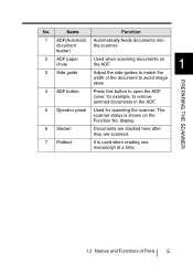
1.2 Names and Functions of Parts This section describes the names of Parts I Front (2) ADF paper chute (1) ADF(Automatic document feeder) (3) Side guide (7) Flatbed (4) ADF button (5) Operator panel (6) Stacker 4 1.2 Names and Functions of parts and their functions.
1.2 Names and Functions of Parts This section describes the names of Parts I Front (2) ADF paper chute (1) ADF(Automatic document feeder) (3) Side guide (7) Flatbed (4) ADF button (5) Operator panel (6) Stacker 4 1.2 Names and Functions of parts and their functions.
Operator Manual
Page 34
... scanned. 7 Flatbed It is shown on the ADF. 1 Adjust the side guides to match the width of Parts 5 No. The scanner status is used when reading one manuscript at a time. 1.2 Names and Functions of the document to remove jammed documents in the ADF. 5 Operator panel Used for example, to avoid image skew. PREPARING THE...
... scanned. 7 Flatbed It is shown on the ADF. 1 Adjust the side guides to match the width of Parts 5 No. The scanner status is used when reading one manuscript at a time. 1.2 Names and Functions of the document to remove jammed documents in the ADF. 5 Operator panel Used for example, to avoid image skew. PREPARING THE...
Operator Manual
Page 35
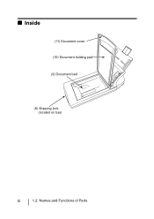
I Inside (11) Document cover (10) Document holding pad (9) Document bed (8) Shipping lock (located on bas) 6 1.2 Names and Functions of Parts
I Inside (11) Document cover (10) Document holding pad (9) Document bed (8) Shipping lock (located on bas) 6 1.2 Names and Functions of Parts

Operator Manual
Page 36
No. Name Function 8 shipping lock Used to fasten the carry unit while the scanner is also called the 1 Flatbed. 10 Document holding Holds the document against the pad document bed. 11 Document cover When closed, this cover holds down the document loaded on the document bed in position. PREPARING THE SCANNER 1.2 Names and Functions of Parts 7 This is being transported. 9 Document bed Load documents here when scanning documents one sheet at a time.
No. Name Function 8 shipping lock Used to fasten the carry unit while the scanner is also called the 1 Flatbed. 10 Document holding Holds the document against the pad document bed. 11 Document cover When closed, this cover holds down the document loaded on the document bed in position. PREPARING THE SCANNER 1.2 Names and Functions of Parts 7 This is being transported. 9 Document bed Load documents here when scanning documents one sheet at a time.

Operator Manual
Page 37
I Rear (12) SCSI ID switch (15) DC inlet (13) SCSI Interface connector (14) USB Interface connector 8 1.2 Names and Functions of Parts
I Rear (12) SCSI ID switch (15) DC inlet (13) SCSI Interface connector (14) USB Interface connector 8 1.2 Names and Functions of Parts

Operator Manual
Page 38
Connect the USB interface cable from the host PC or Computer 1 here. PREPARING THE SCANNER 1.2 Names and Functions of Parts 9 Connect the AC adapter here. No. Name 12 SCSI ID switch 13 SCSI interface connector 14 USB interface connector 15 DC inlet Function Sets the SCSI ID. (Set to "5" before the scanner is shipped from the factory.) Connect the SCSI interface cable from the host PC or Computer here.
Connect the USB interface cable from the host PC or Computer 1 here. PREPARING THE SCANNER 1.2 Names and Functions of Parts 9 Connect the AC adapter here. No. Name 12 SCSI ID switch 13 SCSI interface connector 14 USB interface connector 15 DC inlet Function Sets the SCSI ID. (Set to "5" before the scanner is shipped from the factory.) Connect the SCSI interface cable from the host PC or Computer here.

Operator Manual
Page 39
Pick roller ADF paper chute Pad ASY Document cover Sheet guide 10 1.2 Names and Functions of Parts Removal is possible. I Removable Parts The following shows the parts that can be removed from the scanner.
Pick roller ADF paper chute Pad ASY Document cover Sheet guide 10 1.2 Names and Functions of Parts Removal is possible. I Removable Parts The following shows the parts that can be removed from the scanner.

Operator Manual
Page 95
However, do not use paint thinner or other organic solvents. • Do not allow moisture to be used instead of cleaning fluid. I Cleaning the Flatbed The following parts needs to get inside the device during cleaning. 5.2 Cleaning the Flatbed ATTENTION • Detergent for cleaning windows or glass cleaner can be cleaned in the Flatbed area: •Document holding pad •Document bed Document holding pad Document bed 66 5.2 Cleaning the Flatbed
However, do not use paint thinner or other organic solvents. • Do not allow moisture to be used instead of cleaning fluid. I Cleaning the Flatbed The following parts needs to get inside the device during cleaning. 5.2 Cleaning the Flatbed ATTENTION • Detergent for cleaning windows or glass cleaner can be cleaned in the Flatbed area: •Document holding pad •Document bed Document holding pad Document bed 66 5.2 Cleaning the Flatbed

Operator Manual
Page 97
ATTENTION Do not allow moisture to dry. 4. Gently close the document cover. 68 5.2 Cleaning the Flatbed Wait for cleaned parts to get inside the device during cleaning. 3. •Document holding pad Wipe gently. •Document bed Wipe lightly.
ATTENTION Do not allow moisture to dry. 4. Gently close the document cover. 68 5.2 Cleaning the Flatbed Wait for cleaned parts to get inside the device during cleaning. 3. •Document holding pad Wipe gently. •Document bed Wipe lightly.

Operator Manual
Page 98
...scanner is in the ADF unit: •Pad ASY •Pick roller 5 •Feed roller •Plastic roller •Sheet guide • Glass DAILY CARE 5.3 Cleaning the ADF 69 Before cleaning ADF, disconnect the AC adapter from the power outlet, and wait at least 15 minutes for the glass to the document.... For example, the ADF sometimes must be cleaned in use, the surface of document you are scanning. I Cleaning the ADF The following parts needs to be cleaned more frequently when toner has not sufficiently adhered...
...scanner is in the ADF unit: •Pad ASY •Pick roller 5 •Feed roller •Plastic roller •Sheet guide • Glass DAILY CARE 5.3 Cleaning the ADF 69 Before cleaning ADF, disconnect the AC adapter from the power outlet, and wait at least 15 minutes for the glass to the document.... For example, the ADF sometimes must be cleaned in use, the surface of document you are scanning. I Cleaning the ADF The following parts needs to be cleaned more frequently when toner has not sufficiently adhered...

Operator Manual
Page 100
Clean the following locations with a soft, dry cloth moistened with Cleaner F1. Feed rollers (Four pieces) Pad ASY Sheet guide (A white portion, Two parts) DAILY CARE 5 Pick roller (One pieces) Glass(Two parts) Plastic rollers (Four pieces) 5.3 Cleaning the ADF 71 2.
Clean the following locations with a soft, dry cloth moistened with Cleaner F1. Feed rollers (Four pieces) Pad ASY Sheet guide (A white portion, Two parts) DAILY CARE 5 Pick roller (One pieces) Glass(Two parts) Plastic rollers (Four pieces) 5.3 Cleaning the ADF 71 2.

Operator Manual
Page 166
... to light to the following: Cleaning : If pick errors occur fre- Replacing parts: The service life of the Pad ASY and Pick rollers is sometimes shortened when scanning mediumgrade paper documents. • When the manuscript of Wood containg paper is unavoidable, clean the rollers... frequently. Pay attention to avoid bleed through. • To prevent the rollers from becoming dirty, avoid scanning documents containing large areas written or filled in pencil. quently, clean the Pad ASY 8 and Pick rollers. ATTENTION • Carbonless paper ...
... to light to the following: Cleaning : If pick errors occur fre- Replacing parts: The service life of the Pad ASY and Pick rollers is sometimes shortened when scanning mediumgrade paper documents. • When the manuscript of Wood containg paper is unavoidable, clean the rollers... frequently. Pay attention to avoid bleed through. • To prevent the rollers from becoming dirty, avoid scanning documents containing large areas written or filled in pencil. quently, clean the Pad ASY 8 and Pick rollers. ATTENTION • Carbonless paper ...
Operator Manual
Page 185
...allows communication from black to as an image composed of dots, namely, a binary image. Image emphasis Density is changed from one part of halftone processing. For example, electrical signals are used to express binary numbers in hexadecimal because fewer digits are required. Hexadecimal A...). Since a base-16 system requires 16 digits, numbers 0 through 9 and letters A through F are transferred between the computer and scanner over an interface cable. GL-4 It is read with specified parameters. Weakening this emphasis eliminates spot noise or produces softened images.
...allows communication from black to as an image composed of dots, namely, a binary image. Image emphasis Density is changed from one part of halftone processing. For example, electrical signals are used to express binary numbers in hexadecimal because fewer digits are required. Hexadecimal A...). Since a base-16 system requires 16 digits, numbers 0 through 9 and letters A through F are transferred between the computer and scanner over an interface cable. GL-4 It is read with specified parameters. Weakening this emphasis eliminates spot noise or produces softened images.


