Cleaning & Maintenance
Page 2
...and receiver. • Connect the equipment into an outlet on a circuit different from that interference will not occur in a residential installation. However, there is connected. • Consult the dealer or an experienced radio/TV technician for a Class B digital device, pursuant... to provide reasonable protection against harmful interference in a particular installation. If this equipment does cause harmful interference to operate the equipment. i This equipment generates, uses, and can be determined by ...
...and receiver. • Connect the equipment into an outlet on a circuit different from that interference will not occur in a residential installation. However, there is connected. • Consult the dealer or an experienced radio/TV technician for a Class B digital device, pursuant... to provide reasonable protection against harmful interference in a particular installation. If this equipment does cause harmful interference to operate the equipment. i This equipment generates, uses, and can be determined by ...

Cleaning & Maintenance
Page 17
...wake up the scanner: • Pressing any button. • Setting the paper on the ADF. • Sending a command from the host computer. (Only When the Video Interface Option is installed.) The scanner displays the following screen when waiting for the Start button to be pressed: ...When the Pick roller cleaning is in chapter 2, Cleaning the ADF, and chapter 3, Pick Roller. 1-8 Operation status The operation status...
...wake up the scanner: • Pressing any button. • Setting the paper on the ADF. • Sending a command from the host computer. (Only When the Video Interface Option is installed.) The scanner displays the following screen when waiting for the Start button to be pressed: ...When the Pick roller cleaning is in chapter 2, Cleaning the ADF, and chapter 3, Pick Roller. 1-8 Operation status The operation status...

Cleaning & Maintenance
Page 56
Flatten the curl or use the Flatbed to read the documents. YES NO Is the Pad assembly installed correctly? Do the conditions of the NO documents meet the requirements described in the Operator's Guide? Fan the documents before loading them on the ADF paper chute? YES Have the documents been NO fanned before loading, or reduce the batch size. 11 Symptom Mispick occurs frequently. Install it correctly. (See p. 3-2) YES 4-16
Flatten the curl or use the Flatbed to read the documents. YES NO Is the Pad assembly installed correctly? Do the conditions of the NO documents meet the requirements described in the Operator's Guide? Fan the documents before loading them on the ADF paper chute? YES Have the documents been NO fanned before loading, or reduce the batch size. 11 Symptom Mispick occurs frequently. Install it correctly. (See p. 3-2) YES 4-16

Operator's Guide
Page 3
...the equipment and receiver. • Connect the equipment into an outlet on a circuit different from that interference will not occur in a particular installation. This equipment generates, uses, and can be determined by turning the equipment off and on, the user is encouraged to try to correct the...and found to comply with the referenced device is no guarantee that to which can radiate radio frequency energy and, if not installed and used in a residential installation. These limits are designed to Part 15 of a non-shielded interface cable with the limits for help. NOTICE • ...
...the equipment and receiver. • Connect the equipment into an outlet on a circuit different from that interference will not occur in a particular installation. This equipment generates, uses, and can be determined by turning the equipment off and on, the user is encouraged to try to correct the...and found to comply with the referenced device is no guarantee that to which can radiate radio frequency energy and, if not installed and used in a residential installation. These limits are designed to Part 15 of a non-shielded interface cable with the limits for help. NOTICE • ...

Operator's Guide
Page 7
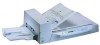
The Reference Guide contains chapters on the following topics: COMPONENTS INSTALLATION AND CONNECTIONS OPERATING INSTRUCTIONS ADF DOCUMENT SPECIFICATIONS SCANNER SPECFICATIONS SETUP MODE It also contains a Glossary of the M4097D. The M4097D is a very fast and highly functional image scanner developed for information about the routine .... This scanner features duplex scanning and high quality image processing with an automatic document feeder (ADF). This manual contains chapters on OPERATING INSTRUCTIONS, CLEANING, REPLACEMENT OF PARTS, ADJUSTMENT and TROUBLESHOOTING. Refer to use the...
The Reference Guide contains chapters on the following topics: COMPONENTS INSTALLATION AND CONNECTIONS OPERATING INSTRUCTIONS ADF DOCUMENT SPECIFICATIONS SCANNER SPECFICATIONS SETUP MODE It also contains a Glossary of the M4097D. The M4097D is a very fast and highly functional image scanner developed for information about the routine .... This scanner features duplex scanning and high quality image processing with an automatic document feeder (ADF). This manual contains chapters on OPERATING INSTRUCTIONS, CLEANING, REPLACEMENT OF PARTS, ADJUSTMENT and TROUBLESHOOTING. Refer to use the...
Operator's Guide
Page 9
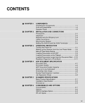
...COMPONENTS Checking the Components 1-1 Units and Assemblies 1-2 Operator Panel 1-5 INSTALLATION AND CONNECTIONS Precautions 2-1 Inspection 2-2 Repositioning the Shipping Lock 2-4 Cable Connections 2-5 Mounting the Stacker 2-7 Setting the SCSI ID and the SCSI Terminator 2-8 OPERATING INSTRUCTION Turning the Power On 3-1 Waking up the ...Scanner from the Low Power Mode ....... 3-2 Manual Feed Mode Setting 3-3 Loading Documents on the ADF 3-4 Loading Documents on ...
...COMPONENTS Checking the Components 1-1 Units and Assemblies 1-2 Operator Panel 1-5 INSTALLATION AND CONNECTIONS Precautions 2-1 Inspection 2-2 Repositioning the Shipping Lock 2-4 Cable Connections 2-5 Mounting the Stacker 2-7 Setting the SCSI ID and the SCSI Terminator 2-8 OPERATING INSTRUCTION Turning the Power On 3-1 Waking up the ...Scanner from the Low Power Mode ....... 3-2 Manual Feed Mode Setting 3-3 Loading Documents on the ADF 3-4 Loading Documents on ...

Operator's Guide
Page 11
COMPONENTS COMPONENTS INSTALLATION AND INSTALLATION AND CONNECTIONS CONNECTIONS OPERATING INSTRUCTION OPERATING INSTRUCTION DOCUMENT SPECIFICATION DOCUMENT SPECIFICATION SCANNER SPECIFICATIONS SPECIFICATIONS CONSUMABLES AND CONSUMABLES AND OPTIONS OPTIONS SETUP MODE SETUP MODE GLOSSARY OF TERMS INDEX GLOSSARY OF TERMS INDEX ix
COMPONENTS COMPONENTS INSTALLATION AND INSTALLATION AND CONNECTIONS CONNECTIONS OPERATING INSTRUCTION OPERATING INSTRUCTION DOCUMENT SPECIFICATION DOCUMENT SPECIFICATION SCANNER SPECIFICATIONS SPECIFICATIONS CONSUMABLES AND CONSUMABLES AND OPTIONS OPTIONS SETUP MODE SETUP MODE GLOSSARY OF TERMS INDEX GLOSSARY OF TERMS INDEX ix
Operator's Guide
Page 15
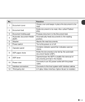
... scanner status. Holds the documents to enable the removal of off. Opens/closes the ADF to be read . A Fujitsu Video Interface Option Board is installed. 1-3 Holds document to an AC power outlet with interface cables. Connects to be fed... by the automatic document feeder (ADF). Turns the power on of documents jammed in place the document to be read . Automatically feeds documents to the Document bed. Also called Flatbed (FB...
... scanner status. Holds the documents to enable the removal of off. Opens/closes the ADF to be read . A Fujitsu Video Interface Option Board is installed. 1-3 Holds document to an AC power outlet with interface cables. Connects to be fed... by the automatic document feeder (ADF). Turns the power on of documents jammed in place the document to be read . Automatically feeds documents to the Document bed. Also called Flatbed (FB...

Operator's Guide
Page 20
Operation status The operation status is indicated by the following messages: (Only When the Video Interface Option is installed.) The scanner displays the following screen when waiting for the Start button to be pressed: When the Pick roller cleaning is necessary, the scanner displays the following on the upper line: When the ADF glass cleaning is necessary, the scanner displays the following on the LCD: Clean the Pick roller or the ADF glass in accordance with the manual, "Cleaning and Maintenance". 1-8
Operation status The operation status is indicated by the following messages: (Only When the Video Interface Option is installed.) The scanner displays the following screen when waiting for the Start button to be pressed: When the Pick roller cleaning is necessary, the scanner displays the following on the upper line: When the ADF glass cleaning is necessary, the scanner displays the following on the LCD: Clean the Pick roller or the ADF glass in accordance with the manual, "Cleaning and Maintenance". 1-8

Operator's Guide
Page 25
Precautions Inspection Repositioning the Shipping Lock Cable Connections Mounting the Stacker Setting the SCSI ID and the SCSI Terminator CHAPTER 2 INSTALLATION AND CONNECTIONS The chapter describes how to install and connect the scanner.
Precautions Inspection Repositioning the Shipping Lock Cable Connections Mounting the Stacker Setting the SCSI ID and the SCSI Terminator CHAPTER 2 INSTALLATION AND CONNECTIONS The chapter describes how to install and connect the scanner.

Operator's Guide
Page 26
... If the scanner is used near an air conditioner, copying machine, or TV set, the scanner may cause the scanner to follow when installing the scanner. These environments may shorten the scanner life or cause hardware failures. • Do not place the scanner where liquid spills may...occur. These environments may shorten the scanner life or cause hardware failures. • Do not install the scanner in a place where vibrations may occur. • Be aware of materials that do not install the scanner in the places and environments described below. • Place the scanner away from...
... If the scanner is used near an air conditioner, copying machine, or TV set, the scanner may cause the scanner to follow when installing the scanner. These environments may shorten the scanner life or cause hardware failures. • Do not place the scanner where liquid spills may...occur. These environments may shorten the scanner life or cause hardware failures. • Do not install the scanner in a place where vibrations may occur. • Be aware of materials that do not install the scanner in the places and environments described below. • Place the scanner away from...

Operator's Guide
Page 29
Then, install the shipping lock at position B . Front side Front side Enlarged Shipping Lock (Position for operation) Bottom view B Shipping Lock (Position for storage, ADF side position for shipment) Enlarged section A A Shipping Lock CAUTION (Position for shipment) Before moving or storing the scanner, ...being damaged during shipping, the carrier unit is attached) extends from position A . After placing the carrier unit where it will be installed, change the position of the desktop so that the carrier has been returned to prevent possible damage. Do not set to the ...
Then, install the shipping lock at position B . Front side Front side Enlarged Shipping Lock (Position for operation) Bottom view B Shipping Lock (Position for storage, ADF side position for shipment) Enlarged section A A Shipping Lock CAUTION (Position for shipment) Before moving or storing the scanner, ...being damaged during shipping, the carrier unit is attached) extends from position A . After placing the carrier unit where it will be installed, change the position of the desktop so that the carrier has been returned to prevent possible damage. Do not set to the ...

Operator's Guide
Page 40
ADF 1 Lift the ADF paper chute up and place the shaft in its operating position. ADF paper chute Guide Guide lever ADF lever Stacker Operating position Bar 3-4 Loading Documents on the ADF NOTICE Be sure to change the position of the shipping lock according to "INSTALLATION AND CONNECTION" procedure before operation.
ADF 1 Lift the ADF paper chute up and place the shaft in its operating position. ADF paper chute Guide Guide lever ADF lever Stacker Operating position Bar 3-4 Loading Documents on the ADF NOTICE Be sure to change the position of the shipping lock according to "INSTALLATION AND CONNECTION" procedure before operation.

Operator's Guide
Page 58
Basic Product Specification Installation Specification Dimensions CHAPTER 5 SCANNER SPECIFICATIONS This chapter describes the installation specifications, dimensions, consumables, and options.
Basic Product Specification Installation Specification Dimensions CHAPTER 5 SCANNER SPECIFICATIONS This chapter describes the installation specifications, dimensions, consumables, and options.

Operator's Guide
Page 60
... following table lists the installation specifications of the scanner. Item Dimensions (mm) (Without Hopper and Stacker) Weight (kg) Voltage Input power Phases Frequency Power consumption Device status Ambient condition Temperature ...
... following table lists the installation specifications of the scanner. Item Dimensions (mm) (Without Hopper and Stacker) Weight (kg) Voltage Input power Phases Frequency Power consumption Device status Ambient condition Temperature ...

Operator's Guide
Page 63
Consumables Options Video Interface Option IPC-4D Option CHAPTER 6 CONSUMABLES AND OPTIONS This chapter describes the installation specifications, dimensions, consumables, option.
Consumables Options Video Interface Option IPC-4D Option CHAPTER 6 CONSUMABLES AND OPTIONS This chapter describes the installation specifications, dimensions, consumables, option.

Operator's Guide
Page 66
Secure the board with two screws. Video Interface Option How to Install the VIDEO Interface Option Board 1 Loosen the two screws to prevent damage from static electricity. CAUTION Turn off the power before removing the Third Party slot plate. 2 Insert the board along the rails of the third party slot. NOTICE When the scanner power is connected securely. Make sure that the connector is turned on again, the scanner automatically recognizes the video interface board. 6-3 CAUTION Protective measures are required to remove the plate.
Secure the board with two screws. Video Interface Option How to Install the VIDEO Interface Option Board 1 Loosen the two screws to prevent damage from static electricity. CAUTION Turn off the power before removing the Third Party slot plate. 2 Insert the board along the rails of the third party slot. NOTICE When the scanner power is connected securely. Make sure that the connector is turned on again, the scanner automatically recognizes the video interface board. 6-3 CAUTION Protective measures are required to remove the plate.

Operator's Guide
Page 67
... Screen 2. 5 Select "Simplex" or "Duplex" by pressing or then press . Reading Mode Setting When the Video Interface Option is installed in the third party slot. NOTICE When the video interface option is Installed This section describes the button specifications and setup details for each of the simplex (front-side), duplex (front-side... host computer, the following button operation is displayed on the LCD. 2 Press then the scanner displays Screen M2. 3 Press then the scanner displays Screen 1. 4 Select ADF or FB by pressing or .
... Screen 2. 5 Select "Simplex" or "Duplex" by pressing or then press . Reading Mode Setting When the Video Interface Option is installed in the third party slot. NOTICE When the video interface option is Installed This section describes the button specifications and setup details for each of the simplex (front-side), duplex (front-side... host computer, the following button operation is displayed on the LCD. 2 Press then the scanner displays Screen M2. 3 Press then the scanner displays Screen 1. 4 Select ADF or FB by pressing or .

Operator's Guide
Page 68
... Description Very dark Dark * Dynamic Threshold (DTC mode) * Simplified Dynamic Threshold (IPC mode) Normal Light Very light * This parameter appears only when IPC-4D is installed. 6-5 Then press . The scanner displays Screen 7. Then press . The scanner displays Screen 5. 8 Select Resolution by pressing or . Then press . The scanner displays Screen 4. 7 Select Size...
... Description Very dark Dark * Dynamic Threshold (DTC mode) * Simplified Dynamic Threshold (IPC mode) Normal Light Very light * This parameter appears only when IPC-4D is installed. 6-5 Then press . The scanner displays Screen 7. Then press . The scanner displays Screen 5. 8 Select Resolution by pressing or . Then press . The scanner displays Screen 4. 7 Select Size...

Operator's Guide
Page 69
... specified) by pressing or . 6-6 As the the cursor moves to the right, / may appear. Therefore binary reading is specified. Automatic separation with error diffusion is installed.
... specified) by pressing or . 6-6 As the the cursor moves to the right, / may appear. Therefore binary reading is specified. Automatic separation with error diffusion is installed.


