

Cleaning & Maintenance
Page 11
Units 2 ADF 1 ADF lever 3 ADF paper chute 6 Document cover 7 Document holding pad 5 Stacker 4 Oparator panel 8 Document bed 9 Third party slot 12 Power switch 11 Power inlet 10 Interface connector 1-2
Units 2 ADF 1 ADF lever 3 ADF paper chute 6 Document cover 7 Document holding pad 5 Stacker 4 Oparator panel 8 Document bed 9 Third party slot 12 Power switch 11 Power inlet 10 Interface connector 1-2

Cleaning & Maintenance
Page 13
Assemblies Thumb screw Guide A ASY Stacker Pad ASY Pick roller 2 Pick roller 1 1-4
Assemblies Thumb screw Guide A ASY Stacker Pad ASY Pick roller 2 Pick roller 1 1-4
Operator's Guide
Page 9
...CONNECTIONS Precautions 2-1 Inspection 2-2 Repositioning the Shipping Lock 2-4 Cable Connections 2-5 Mounting the Stacker 2-7 Setting the SCSI ID and the SCSI Terminator 2-8 OPERATING INSTRUCTION Turning the Power On 3-1 Waking up the Scanner from ...the Low Power Mode ....... 3-2 Manual Feed Mode Setting 3-3 Loading Documents on the ADF 3-4 Loading Documents on the Flatbed 3-9 Loading Documents Larger than the Document Bed .... 3-10 Reading a Page from a Thick Book 3-11 ADF...
...CONNECTIONS Precautions 2-1 Inspection 2-2 Repositioning the Shipping Lock 2-4 Cable Connections 2-5 Mounting the Stacker 2-7 Setting the SCSI ID and the SCSI Terminator 2-8 OPERATING INSTRUCTION Turning the Power On 3-1 Waking up the Scanner from ...the Low Power Mode ....... 3-2 Manual Feed Mode Setting 3-3 Loading Documents on the ADF 3-4 Loading Documents on the Flatbed 3-9 Loading Documents Larger than the Document Bed .... 3-10 Reading a Page from a Thick Book 3-11 ADF...

Operator's Guide
Page 14
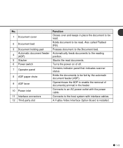
Units and Assemblies This section shows the exterior view and assemblies of each part and describes its functions. Units 1 Document cover 4 Operator panel 3 Document holding pad 2 Document bed 5 Stacker 9 ADF lever 8 ADF paper chute 7 Operator panel 12 Third party slot 6 Power switch 11 Interface connector 10 Power inlet M4097D NOTICE The shipping lock must be switched to page 2-4. 1-2 Refer to the operating position before the scanner can be used. This section also provides the name of the scanner.
Units and Assemblies This section shows the exterior view and assemblies of each part and describes its functions. Units 1 Document cover 4 Operator panel 3 Document holding pad 2 Document bed 5 Stacker 9 ADF lever 8 ADF paper chute 7 Operator panel 12 Third party slot 6 Power switch 11 Interface connector 10 Power inlet M4097D NOTICE The shipping lock must be switched to page 2-4. 1-2 Refer to the operating position before the scanner can be used. This section also provides the name of the scanner.
Operator's Guide
Page 15
Opens/closes the ADF to the host system with the power cable. A Fujitsu Video Interface Option Board is installed. 1-3 Also called Flatbed (FB). Holds the documents to the Document bed. Connects to enable the removal of off. Stacks the read . ... read documents. Connects to be read. No. 1 Document cover 2 Document bed 3 Document holding pad 4 Automatic document feeder (ADF) 5 Stacker 6 Power switch 7 Operator panel 8 ADF paper chute 9 ADF lever 10 Power inlet 11 Interface connectors 12 Third party slot Function Closes over and keeps in the feeder.
Opens/closes the ADF to the host system with the power cable. A Fujitsu Video Interface Option Board is installed. 1-3 Also called Flatbed (FB). Holds the documents to the Document bed. Connects to enable the removal of off. Stacks the read . ... read documents. Connects to be read. No. 1 Document cover 2 Document bed 3 Document holding pad 4 Automatic document feeder (ADF) 5 Stacker 6 Power switch 7 Operator panel 8 ADF paper chute 9 ADF lever 10 Power inlet 11 Interface connectors 12 Third party slot Function Closes over and keeps in the feeder.

Operator's Guide
Page 16
Assemblies Thumb screw Guide A ASY Stacker Pad ASY Pick roller 2 Pick roller 1 1-4
Assemblies Thumb screw Guide A ASY Stacker Pad ASY Pick roller 2 Pick roller 1 1-4

Operator's Guide
Page 25
CHAPTER 2 INSTALLATION AND CONNECTIONS The chapter describes how to install and connect the scanner. Precautions Inspection Repositioning the Shipping Lock Cable Connections Mounting the Stacker Setting the SCSI ID and the SCSI Terminator
CHAPTER 2 INSTALLATION AND CONNECTIONS The chapter describes how to install and connect the scanner. Precautions Inspection Repositioning the Shipping Lock Cable Connections Mounting the Stacker Setting the SCSI ID and the SCSI Terminator

Operator's Guide
Page 32
Stacker Pin (inside) Claw 2-7 Hook the pins on the stacker to the claws on the image scanner. Mounting the Stacker Mount the stacker using the following procedure. 1 Mount the stacker.
Stacker Pin (inside) Claw 2-7 Hook the pins on the stacker to the claws on the image scanner. Mounting the Stacker Mount the stacker using the following procedure. 1 Mount the stacker.

Operator's Guide
Page 40
ADF paper chute Guide Guide lever ADF lever Stacker Operating position Bar 3-4 Loading Documents on the ADF NOTICE Be sure to change the position of the shipping lock according to "INSTALLATION AND CONNECTION" procedure before operation. ADF 1 Lift the ADF paper chute up and place the shaft in its operating position.
ADF paper chute Guide Guide lever ADF lever Stacker Operating position Bar 3-4 Loading Documents on the ADF NOTICE Be sure to change the position of the shipping lock according to "INSTALLATION AND CONNECTION" procedure before operation. ADF 1 Lift the ADF paper chute up and place the shaft in its operating position.

Operator's Guide
Page 42
ADF paper chute Stacker 3-6 3 Preparing the Paper • Place the documents face down, with the top to the paper size, and then flip out the plate. Top A B D A BC (For portrait mode) C NOTICE Reduce the batch size of the documents if double feed or misspick occurs. 4 Adjust the stacker extension to the left as shown...
ADF paper chute Stacker 3-6 3 Preparing the Paper • Place the documents face down, with the top to the paper size, and then flip out the plate. Top A B D A BC (For portrait mode) C NOTICE Reduce the batch size of the documents if double feed or misspick occurs. 4 Adjust the stacker extension to the left as shown...

Operator's Guide
Page 44
6 After the read command is issued from the host system and the documents are read, scanned documents are expelled into the stacker for removal. 3-8
6 After the read command is issued from the host system and the documents are read, scanned documents are expelled into the stacker for removal. 3-8

Operator's Guide
Page 60
Installation Specification The following table lists the installation specifications of the scanner. Item Dimensions (mm) (Without Hopper and Stacker) Weight (kg) Voltage Input power Phases Frequency Power consumption Device status Ambient condition Temperature Humidity Heat capacity Shipping Weight (kg) Specification Depth Width Height 696 (...
Installation Specification The following table lists the installation specifications of the scanner. Item Dimensions (mm) (Without Hopper and Stacker) Weight (kg) Voltage Input power Phases Frequency Power consumption Device status Ambient condition Temperature Humidity Heat capacity Shipping Weight (kg) Specification Depth Width Height 696 (...
Operator's Guide
Page 96
... 1-6 R Reading mode 3-2 face 3-2 Resetting abrasion counter 6-6 Resolution 3-3 Reviewing the IPC/Memory Status 6-9 S Scanner 1-1 Setting double feed detection 6-3 IPC preset mode 6-4 Offset 6-7 picking start time 6-6 SCSI-ID 6-9 time-out limit 6-7 Setup mode 6-1, 6-2 Simplex 3-2 Size 3-3 Specifications 5-1 Stacker 1-2, 2-7 Start button 1-5, 1-6 Stop button 1-5, 1-6 T Terminator 1-1 Temporary error 1-9 Third party slot 1-2, 1-3 Turning the power on 3-1 the power off 2-5
... 1-6 R Reading mode 3-2 face 3-2 Resetting abrasion counter 6-6 Resolution 3-3 Reviewing the IPC/Memory Status 6-9 S Scanner 1-1 Setting double feed detection 6-3 IPC preset mode 6-4 Offset 6-7 picking start time 6-6 SCSI-ID 6-9 time-out limit 6-7 Setup mode 6-1, 6-2 Simplex 3-2 Size 3-3 Specifications 5-1 Stacker 1-2, 2-7 Start button 1-5, 1-6 Stop button 1-5, 1-6 T Terminator 1-1 Temporary error 1-9 Third party slot 1-2, 1-3 Turning the power on 3-1 the power off 2-5