
Manual/User Guide
Page 4
Document number T10/1236D Rev.20 [NCITS.351:2001] T10/996D Rev.8c [NCITS.306:1998] T10/1157D Rev.20 T10/1365D Rev.7 Title SCSI Primary Commands-2 (SPC-2) SCSI-3 Block Commands (SBC) SCSI Architecture Model-2 (SAM-2) SCSI Parallel Interface-4 (SPI-4) *1 ANSI = American National Standard Institute In case of conflict between this manual and any referenced document, this manual comply with the following ANSI (*1) standards. ii C141-E185 Related Standards Product specifications and functions described in this manual takes precedence.
Document number T10/1236D Rev.20 [NCITS.351:2001] T10/996D Rev.8c [NCITS.306:1998] T10/1157D Rev.20 T10/1365D Rev.7 Title SCSI Primary Commands-2 (SPC-2) SCSI-3 Block Commands (SBC) SCSI Architecture Model-2 (SAM-2) SCSI Parallel Interface-4 (SPI-4) *1 ANSI = American National Standard Institute In case of conflict between this manual and any referenced document, this manual comply with the following ANSI (*1) standards. ii C141-E185 Related Standards Product specifications and functions described in this manual takes precedence.

Manual/User Guide
Page 7
... To short the setting terminal, use the short plug attached when the device is on . • Write protect: CN2 9-10 (NP model only) 3. Do not connect or disconnect cables when power is shipped from the factory. Important Alert Items Important Alert Messages The important alert ...messages in this section. Hot temperature To prevent injury, do not handle the drive until after the device has 5-1 cooled sufficiently after turning off the power. Alert message Page Data loss 2-5 For MAS series, Reed ...
... To short the setting terminal, use the short plug attached when the device is on . • Write protect: CN2 9-10 (NP model only) 3. Do not connect or disconnect cables when power is shipped from the factory. Important Alert Items Important Alert Messages The important alert ...messages in this section. Hot temperature To prevent injury, do not handle the drive until after the device has 5-1 cooled sufficiently after turning off the power. Alert message Page Data loss 2-5 For MAS series, Reed ...

Manual/User Guide
Page 11
... page CHAPTER 1 GENERAL DESCRIPTION 1-1 1.1 Standard Features ...1-2 1.2 Hardware Structure...1-6 1.3 System Configuration ...1-9 CHAPTER 2 SPECIFICATIONS 2-1 2.1 Hardware Specifications...2-1 2.1.1 Model name and order number 2-1 2.1.2 Function specifications...2-2 2.1.3 Environmental specifications 2-4 2.1.4 Error rate ...2-5 2.1.5 Reliability...2-5 2.2 SCSI Function Specifications 2-7 CHAPTER 3 ...Mounting ...4-4 4.1.3 Notes on mounting ...4-4 4.2 Power Supply Requirements 4-8 4.3 Connection Requirements 4-11 4.3.1 SCA2 connector type 16-bit SCSI model (NC model 4-11 C141-E185 ix
... page CHAPTER 1 GENERAL DESCRIPTION 1-1 1.1 Standard Features ...1-2 1.2 Hardware Structure...1-6 1.3 System Configuration ...1-9 CHAPTER 2 SPECIFICATIONS 2-1 2.1 Hardware Specifications...2-1 2.1.1 Model name and order number 2-1 2.1.2 Function specifications...2-2 2.1.3 Environmental specifications 2-4 2.1.4 Error rate ...2-5 2.1.5 Reliability...2-5 2.2 SCSI Function Specifications 2-7 CHAPTER 3 ...Mounting ...4-4 4.1.3 Notes on mounting ...4-4 4.2 Power Supply Requirements 4-8 4.3 Connection Requirements 4-11 4.3.1 SCA2 connector type 16-bit SCSI model (NC model 4-11 C141-E185 ix

Manual/User Guide
Page 12
...model (NP model 4-13 Cable connector requirements 4-20 External operator panel (on NP model drives only 4-21 CHAPTER 5 INSTALLATION 5-1 5.1 Notes on Handling Drives 5-1 5.2 Connections...5-3 5.3 Setting Terminals ...5-5 5.3.1 SCSI ID setting...5-6 5.3.2 Each mode setting ...5-8 5.3.3 Mode settings ...5-10 5.4 Mounting Drives...5-13 5.6.2 Checking SCSI connection 5-14 5.6.3 Formatting ...5-17 5.6.4 Setting parameters ...5-19 5.7 Dismounting Drives...5-23 5.8 Spare Disk Drive ...5-23 CHAPTER 6 DIAGNOSTICS AND MAINTENANCE 6-1 6.1 Diagnostics ...6-1 6.1.1 Self-diagnostics ...6-1 6.1.2 Test ...
...model (NP model 4-13 Cable connector requirements 4-20 External operator panel (on NP model drives only 4-21 CHAPTER 5 INSTALLATION 5-1 5.1 Notes on Handling Drives 5-1 5.2 Connections...5-3 5.3 Setting Terminals ...5-5 5.3.1 SCSI ID setting...5-6 5.3.2 Each mode setting ...5-8 5.3.3 Mode settings ...5-10 5.4 Mounting Drives...5-13 5.6.2 Checking SCSI connection 5-14 5.6.3 Formatting ...5-17 5.6.4 Setting parameters ...5-19 5.7 Dismounting Drives...5-23 5.8 Spare Disk Drive ...5-23 CHAPTER 6 DIAGNOSTICS AND MAINTENANCE 6-1 6.1 Diagnostics ...6-1 6.1.1 Self-diagnostics ...6-1 6.1.2 Test ...

Manual/User Guide
Page 13
...6.4.2 6.4.3 6.4.4 6.4.5 Diagnostic test ...6-12 Troubleshooting Procedures 6-13 Outline of troubleshooting procedures 6-13 Troubleshooting with disk drive replacement in the field 6-13 Troubleshooting at the repair site 6-15 Troubleshooting with parts replacement in the factory ...), (B-47-xx), (B-49-00), (B-4D-xx) and (B-4E-00): SCSI interface error 7-4 APPENDIX A SETTING TERMINALS A-1 A.1 Setting Terminals (on NP model only A-2 APPENDIX B CONNECTOR SIGNAL ALLOCATION B-1 B.1 SCSI Connector Signal Allocation: SCA2 type LVD 16-bit SCSI B-2 B.2 SCSI Connector Signal Allocation: 68 pin ...
...6.4.2 6.4.3 6.4.4 6.4.5 Diagnostic test ...6-12 Troubleshooting Procedures 6-13 Outline of troubleshooting procedures 6-13 Troubleshooting with disk drive replacement in the field 6-13 Troubleshooting at the repair site 6-15 Troubleshooting with parts replacement in the factory ...), (B-47-xx), (B-49-00), (B-4D-xx) and (B-4E-00): SCSI interface error 7-4 APPENDIX A SETTING TERMINALS A-1 A.1 Setting Terminals (on NP model only A-2 APPENDIX B CONNECTOR SIGNAL ALLOCATION B-1 B.1 SCSI Connector Signal Allocation: SCA2 type LVD 16-bit SCSI B-2 B.2 SCSI Connector Signal Allocation: 68 pin ...

Manual/User Guide
Page 14
FIGURES Figure 1.1 Figure 1.2 Figure 1.3 Figure 1.4 page NC model drives outer view 1-6 NP model drives outer view 1-6 Disk/head configuration...1-7 System configuration ...1-9 Figure 3.1 Figure 3.2 Figure 3.3 Figure 3.4 Figure 3.5 Figure 3.6 Figure ...Figure 4.7 Figure 4.8 Figure 4.9 Figure 4.10 Figure 4.11 Figure 4.12 Figure 4.13 Figure 4.14 Figure 4.15 Figure 4.16 Figure 4.17 Figure 4.18 Figure 4.19 NC external dimensions...4-2 NP external dimensions ...4-3 IDD orientations ...4-4 Mounting frame structure ...4-5 Limitation of side-mounting 4-5 Surface temperature measurement points 4-6...
FIGURES Figure 1.1 Figure 1.2 Figure 1.3 Figure 1.4 page NC model drives outer view 1-6 NP model drives outer view 1-6 Disk/head configuration...1-7 System configuration ...1-9 Figure 3.1 Figure 3.2 Figure 3.3 Figure 3.4 Figure 3.5 Figure 3.6 Figure ...Figure 4.7 Figure 4.8 Figure 4.9 Figure 4.10 Figure 4.11 Figure 4.12 Figure 4.13 Figure 4.14 Figure 4.15 Figure 4.16 Figure 4.17 Figure 4.18 Figure 4.19 NC external dimensions...4-2 NP external dimensions ...4-3 IDD orientations ...4-4 Mounting frame structure ...4-5 Limitation of side-mounting 4-5 Surface temperature measurement points 4-6...
Manual/User Guide
Page 15
...-bit SCSI ID external input 4-16 Output signal for external LED 4-18 SCSI cables connection ...4-19 External operator panel circuit example 4-21 Figure 5.1 Figure 5.2 Figure 5.3 Figure 5.4 Figure 5.5 SCSI bus connections ...5-4 Setting terminals location (on NP models only 5-5 CN2 setting terminal (on NP models only 5-6 Checking the SCSI connection (A 5-15 Checking the SCSI connection...
...-bit SCSI ID external input 4-16 Output signal for external LED 4-18 SCSI cables connection ...4-19 External operator panel circuit example 4-21 Figure 5.1 Figure 5.2 Figure 5.3 Figure 5.4 Figure 5.5 SCSI bus connections ...5-4 Setting terminals location (on NP models only 5-5 CN2 setting terminal (on NP models only 5-6 Checking the SCSI connection (A 5-15 Checking the SCSI connection...

Manual/User Guide
Page 16
... mode settings (by CHANGE DEFINITION command 5-10 Table 5.8 Setting check list (NP model only 5-11 Table 6.1 Self-diagnostic functions ...6-1 Table 6.2 System-level field troubleshooting 6-14 Table 6.3 Disk drive troubleshooting ...6-15 Table 7.1 Definition of sense data ...7-3 Table A.1 CN2 setting terminal (on NP model drives only A-2 Table B.1 SCSI connector (SCA2 type LVD 16-bit SCSI): CN1...
... mode settings (by CHANGE DEFINITION command 5-10 Table 5.8 Setting check list (NP model only 5-11 Table 6.1 Self-diagnostic functions ...6-1 Table 6.2 System-level field troubleshooting 6-14 Table 6.3 Disk drive troubleshooting ...6-15 Table 7.1 Definition of sense data ...7-3 Table A.1 CN2 setting terminal (on NP model drives only A-2 Table B.1 SCSI connector (SCA2 type LVD 16-bit SCSI): CN1...
Manual/User Guide
Page 18
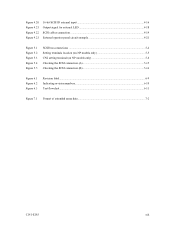
... of connectable SCSI devices on the same SCSI bus is varied as follows. • 8-bit SCSI: 8 drives max. (option for NP model) • 16-bit SCSI: 16 drives max. (4) High speed data transfer Such a high data transfer rate on the SCSI bus is 320 MB/s maximum at the synchronous mode....-bit SCSI: The data transfer rate on the SCSI bus can manipulate data through logical block addressing regardless of the physical characteristics of the disk drive. 1.1 Standard Features (1) Compactness Since the SCSI controller circuit is embedded in the IDD. • 8-bit SCSI: The data transfer rate on...
... of connectable SCSI devices on the same SCSI bus is varied as follows. • 8-bit SCSI: 8 drives max. (option for NP model) • 16-bit SCSI: 16 drives max. (4) High speed data transfer Such a high data transfer rate on the SCSI bus is 320 MB/s maximum at the synchronous mode....-bit SCSI: The data transfer rate on the SCSI bus can manipulate data through logical block addressing regardless of the physical characteristics of the disk drive. 1.1 Standard Features (1) Compactness Since the SCSI controller circuit is embedded in the IDD. • 8-bit SCSI: The data transfer rate on...
Manual/User Guide
Page 22
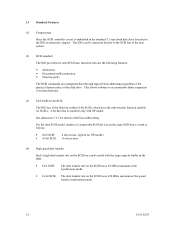
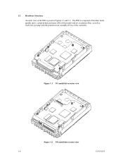
1.2 Hardware Structure An outer view of the controller. The IDD is composed of the disk, head, spindle motor, mounted disk enclosure (DE) with actuator and air circulation filter, as well as read/write pre-amp with the printed circuit assembly (PCA) of the IDD is given in Figures 1.1 and 1.2. Figure 1.1 NC model drives outer view Figure 1.2 NP model drives outer view 1-6 C141-E185
1.2 Hardware Structure An outer view of the controller. The IDD is composed of the disk, head, spindle motor, mounted disk enclosure (DE) with actuator and air circulation filter, as well as read/write pre-amp with the printed circuit assembly (PCA) of the IDD is given in Figures 1.1 and 1.2. Figure 1.1 NC model drives outer view Figure 1.2 NP model drives outer view 1-6 C141-E185

Manual/User Guide
Page 23
...The heads are positioned on the CCS zone over the disks when the power is off or the spindle motor is controlled by a direct-drive hall-less DC motor. The disks are rotated by a feedback circuit using the counter electromotive current to precisely maintain of disks and heads Base... for MAS series. MAS3735NC/NP: 4 MAS3367NC/NP: 2 MAS3184NC/NP: 1 (2) Heads The MR (Magnet - Resistive) of 25 mm (0.98 inch) for at the end of the actuator arm is controlled and positioned via feedback of disks. C141-E185 1-7 Each model contains following number of servo information in contact with the...
...The heads are positioned on the CCS zone over the disks when the power is off or the spindle motor is controlled by a direct-drive hall-less DC motor. The disks are rotated by a feedback circuit using the counter electromotive current to precisely maintain of disks and heads Base... for MAS series. MAS3735NC/NP: 4 MAS3367NC/NP: 2 MAS3184NC/NP: 1 (2) Heads The MR (Magnet - Resistive) of 25 mm (0.98 inch) for at the end of the actuator arm is controlled and positioned via feedback of disks. C141-E185 1-7 Each model contains following number of servo information in contact with the...
Manual/User Guide
Page 26
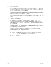
For input/output operation, a peripheral device attached to the SCSI bus that the whole volume of disk drive is addressed in unit called as logical unit. The IDD is constructed so that operates as target is a single logical unit, the selectable number of ... multi-SCSI devices. (2) Addressing of SCSI ID and LUN are as follows: • SCSI ID: • LUN: 8-bit SCSI:Selectable from 0 to 7 (option for NP model, switch selectable) 16-bit SCSI:Selectable from 0 to 15 (switch selectable) 0 (fixed) 1-10 C141-E185 The initiator selects one SCSI device by specifying that operate...
For input/output operation, a peripheral device attached to the SCSI bus that the whole volume of disk drive is addressed in unit called as logical unit. The IDD is constructed so that operates as target is a single logical unit, the selectable number of ... multi-SCSI devices. (2) Addressing of SCSI ID and LUN are as follows: • SCSI ID: • LUN: 8-bit SCSI:Selectable from 0 to 7 (option for NP model, switch selectable) 16-bit SCSI:Selectable from 0 to 15 (switch selectable) 0 (fixed) 1-10 C141-E185 The initiator selects one SCSI device by specifying that operate...

Manual/User Guide
Page 27
... numbers Model name MAS3735NC MAS3735NP MAS3367NC MAS3367NP MAS3184NC MAS3184NP Order number CA06227-B400 CA06227-B460 CA06227-B200 CA06227-B260 CA06227-B100 CA06227-B160 SCSI type SCA2, LVD 68-pin, LVD SCA2, LVD 68-pin, LVD SCA2, LVD 68-pin, LVD Capacity Number of (user area) disks 73.49 GB 4 36.77 GB 2 18.37 GB 1 Number...
... numbers Model name MAS3735NC MAS3735NP MAS3367NC MAS3367NP MAS3184NC MAS3184NP Order number CA06227-B400 CA06227-B460 CA06227-B200 CA06227-B260 CA06227-B100 CA06227-B160 SCSI type SCA2, LVD 68-pin, LVD SCA2, LVD 68-pin, LVD SCA2, LVD 68-pin, LVD Capacity Number of (user area) disks 73.49 GB 4 36.77 GB 2 18.37 GB 1 Number...

Manual/User Guide
Page 33
... resistor is mounted on the PCA × TERMPWR signal send function Ο Connector 68 pin P cable connector 80 pin SCA2 connector Ο (NP model) Ο (NC model) Data bus parity (Data bus CRC) Ο Bus arbitration function Ο Disconnection/reconnection function Ο Addressing SCSI ID 16-bit SCSI LUN (logical unit...
... resistor is mounted on the PCA × TERMPWR signal send function Ο Connector 68 pin P cable connector 80 pin SCA2 connector Ο (NP model) Ο (NC model) Data bus parity (Data bus CRC) Ο Bus arbitration function Ο Disconnection/reconnection function Ο Addressing SCSI ID 16-bit SCSI LUN (logical unit...

Manual/User Guide
Page 43
... of logical data blocks are used. Table 3.4 Format capacity Model Data heads Data block length MAS3735NC/NP 8 MAS3367NC/NP 4 512 MAS3184NC/NP 2 User blocks 143,552,136 71,819,496 35,890,512 Format capacity (GB) 73.49 36.77 18.37 Note: Total number of spare sectors is the general ...block length and the default spare area are specified with the parameter in each physical sector at formatting. The INIT specifies the data to each drive. 3.1.5 Format capacity The size of the usable area for storing user data on the disk medium. The IDD relates a logical data block ...
... of logical data blocks are used. Table 3.4 Format capacity Model Data heads Data block length MAS3735NC/NP 8 MAS3367NC/NP 4 512 MAS3184NC/NP 2 User blocks 143,552,136 71,819,496 35,890,512 Format capacity (GB) 73.49 36.77 18.37 Note: Total number of spare sectors is the general ...block length and the default spare area are specified with the parameter in each physical sector at formatting. The INIT specifies the data to each drive. 3.1.5 Format capacity The size of the usable area for storing user data on the disk medium. The IDD relates a logical data block ...

Manual/User Guide
Page 57
.... (7) Leak magnetic flux The IDD uses a high performance magnet to avoid the influence of the IDD is shown in Figure 4.7. [Surface P'] • Setting terminal (MP model only) • External operator panel connector [Surface P] • Cable connection [Surface R] • Hole for mounting screw [Surface Q] • Hole for mounting screw Figure 4.7 Service clearance...
.... (7) Leak magnetic flux The IDD uses a high performance magnet to avoid the influence of the IDD is shown in Figure 4.7. [Surface P'] • Setting terminal (MP model only) • External operator panel connector [Surface P] • Cable connection [Surface R] • Hole for mounting screw [Surface Q] • Hole for mounting screw Figure 4.7 Service clearance...
Manual/User Guide
Page 60
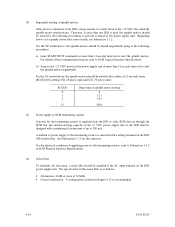
...the IDD, a large amount of the power supply unit. The specification of this noise filter is turned on to short. For the NC model drives, the spindle motors should be installed at more than 12-second intervals to 200 mA. For the electrical condition of up to start control ...power supply unit at more than 12-second intervals to Subsection 1.4.2 in the +12 VDC line when the spindle motor rotation starts. For the NP model drives, the spindle motors should be started after a delay of this selection. For details of 12 seconds times [SCSI ID] by the following procedures. (4)...
...the IDD, a large amount of the power supply unit. The specification of this noise filter is turned on to short. For the NC model drives, the spindle motors should be installed at more than 12-second intervals to 200 mA. For the electrical condition of up to start control ...power supply unit at more than 12-second intervals to Subsection 1.4.2 in the +12 VDC line when the spindle motor rotation starts. For the NP model drives, the spindle motors should be started after a delay of this selection. For details of 12 seconds times [SCSI ID] by the following procedures. (4)...
Manual/User Guide
Page 61
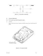
Figure 4.12 AC noise filter (recommended) 4.3 Connection Requirements 4.3.1 SCA2 connector type 16-bit SCSI model (NC model) (1) Connectors Figure 4.13 shows the locations of connectors on the SCA2 connector type 16-bit SCSI model (NC model). SCSI connector (CN1) (including power supply) Figure 4.13 NC connectors location C141-E185 4-11
Figure 4.12 AC noise filter (recommended) 4.3 Connection Requirements 4.3.1 SCA2 connector type 16-bit SCSI model (NC model) (1) Connectors Figure 4.13 shows the locations of connectors on the SCA2 connector type 16-bit SCSI model (NC model). SCSI connector (CN1) (including power supply) Figure 4.13 NC connectors location C141-E185 4-11
Manual/User Guide
Page 62
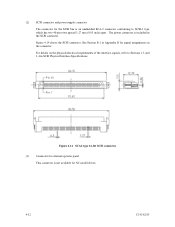
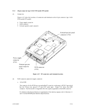
... the interface signals, refer to SCSI-3 type which has two 40-pin rows spaced 1.27 mm (0.05 inch) apart. See Section B.1 in Appendix B for NC model drives. 4-12 C141-E185
... the interface signals, refer to SCSI-3 type which has two 40-pin rows spaced 1.27 mm (0.05 inch) apart. See Section B.1 in Appendix B for NC model drives. 4-12 C141-E185
Manual/User Guide
Page 63
... See Section B.2 in the SCSI Physical Interface Specifications. 4.3.2 68 pin connector type 16-bit SCSI model (NP model) (1) Connectors Figures 4.15 show the locations of connectors and terminals on the 68 pin connector type 16-bit SCSI model (NP model). • Power supply connector • SCSI connector • External operator panel connector External operator...
... See Section B.2 in the SCSI Physical Interface Specifications. 4.3.2 68 pin connector type 16-bit SCSI model (NP model) (1) Connectors Figures 4.15 show the locations of connectors and terminals on the 68 pin connector type 16-bit SCSI model (NP model). • Power supply connector • SCSI connector • External operator panel connector External operator...

