
Manual/User Guide
Page 88
5.3 Host Commands Table 5.3 Command code and parameters (2 of 2) Command name Command code (Bit) Parameters used 7 6 5 4 3 2 1 0 FR SC SN CY DH IDLE IMMEDIATE 1 0 0 1 0 1 0 1 NNNND 11100001 STANDBY 1 0 0 1 0 1 1 0 NYNND 11100010 STANDBY IMMEDIATE 1 0 0 1 0 1 0 0 NNNND 11100000 SLEEP 1 0 0 1 1 0...1 0 0 0 1 NNNND SECURITY UNLOCK 1 1 1 1 0 0 1 0 NNNND FLUSH CACHE 1 1 1 0 0 1 1 1 NNNND Notes: FR: Features Register CY: Cylinder Registers SC: Sector Count Register DH: Drive/Head Register SN: Sector Number Register R: Retry at error 1 = Without retry 0 = With retry Y: Necessary to set...
5.3 Host Commands Table 5.3 Command code and parameters (2 of 2) Command name Command code (Bit) Parameters used 7 6 5 4 3 2 1 0 FR SC SN CY DH IDLE IMMEDIATE 1 0 0 1 0 1 0 1 NNNND 11100001 STANDBY 1 0 0 1 0 1 1 0 NYNND 11100010 STANDBY IMMEDIATE 1 0 0 1 0 1 0 0 NNNND 11100000 SLEEP 1 0 0 1 1 0...1 0 0 0 1 NNNND SECURITY UNLOCK 1 1 1 1 0 0 1 0 NNNND FLUSH CACHE 1 1 1 0 0 1 1 1 NNNND Notes: FR: Features Register CY: Cylinder Registers SC: Sector Count Register DH: Drive/Head Register SN: Sector Number Register R: Retry at error 1 = Without retry 0 = With retry Y: Necessary to set...
Manual/User Guide
Page 104
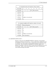
...the arrangements and values of sectors/track Error infomation (12) IDENTIFY DEVICE (X'EC') The host system issues the IDENTIFY DEVICE command to be read parameter information (512 bytes) from the device. C141-E088-03EN 5-31 5.3 Host Commands At command issuance (I /O registers contents to read ) ...(DH) 1F5H(CH) 1F4 (CL) H 1F3H(SN) 1F2 (SC) H 1F1H(ER) Status information × × × DV Max. Upon receipt of this command, the drive sets the BSY bit of sectors/track H 1F1H(FR) xx At command completion (I /O registers setting contents) 1F7 (CM) 1 0 0 1 0 0 0 1 H 1F6H(DH)...
...the arrangements and values of sectors/track Error infomation (12) IDENTIFY DEVICE (X'EC') The host system issues the IDENTIFY DEVICE command to be read parameter information (512 bytes) from the device. C141-E088-03EN 5-31 5.3 Host Commands At command issuance (I /O registers contents to read ) ...(DH) 1F5H(CH) 1F4 (CL) H 1F3H(SN) 1F2 (SC) H 1F1H(ER) Status information × × × DV Max. Upon receipt of this command, the drive sets the BSY bit of sectors/track H 1F1H(FR) xx At command completion (I /O registers setting contents) 1F7 (CM) 1 0 0 1 0 0 0 1 H 1F6H(DH)...

Manual/User Guide
Page 113
...mode depends on , to be executed. Interface (14) SET FEATURES (X'EF') The host system issues the SET FEATURES command to set parameters in the Features register for write cache). Disables read cache function. At power-on or after software reset. 5-40 C141-E088-03EN ... using the Sector Count register. Disables the reverting to power-on default settings after software reset. Table 5.5 Features register values and settable modes Features Register Drive operation mode X'02' X'03' X'05' X'55' X'66' X'82' X'85' X'AA' X'BB' X'CC' Enables the write cache function....
...mode depends on , to be executed. Interface (14) SET FEATURES (X'EF') The host system issues the SET FEATURES command to set parameters in the Features register for write cache). Disables read cache function. At power-on or after software reset. 5-40 C141-E088-03EN ... using the Sector Count register. Disables the reverting to power-on default settings after software reset. Table 5.5 Features register values and settable modes Features Register Drive operation mode X'02' X'03' X'05' X'55' X'66' X'82' X'85' X'AA' X'BB' X'CC' Enables the write cache function....
Manual/User Guide
Page 152
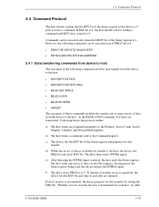
...the transfer one sector of the Status register is 1. Following shows the protocol outline. b) The host writes a command code to 0. f) The drive clears DRQ bit to the Command register. If transfer of data is available for data transfer by setting the DRQ bit. d) When one sector...BSY bit. However, the following commands can be executed even if DRDY bit is 0. • EXECUTE DEVICE DIAGNOSTIC • INITIALIZE DEVICE PARAMETERS 5.4.1 Data transferring commands from device to host The execution of the following commands involves data transfer from the device to the host. In the...
...the transfer one sector of the Status register is 1. Following shows the protocol outline. b) The host writes a command code to 0. f) The drive clears DRQ bit to the Command register. If transfer of data is available for data transfer by setting the DRQ bit. d) When one sector...BSY bit. However, the following commands can be executed even if DRDY bit is 0. • EXECUTE DEVICE DIAGNOSTIC • INITIALIZE DEVICE PARAMETERS 5.4.1 Data transferring commands from device to host The execution of the following commands involves data transfer from the device to the host. In the...
Manual/User Guide
Page 155
... bit of data through the Data register. g) After detecting the INTRQ signal assertion, the host reads the Status register. f) When the drive completes transferring the data of WRITE SECTOR(S) command protocol. If transfer of the first sector, the device sets DRQ bit and clears BSY ...interrupt signal). b) The host writes a command code in the Command register. c) When the device is requested, the drive sets the DRQ bit. Interface a) The host writes any required parameters to receive the data of another sector is requested, steps d) and after are repeated. e) The device clears the ...
... bit of data through the Data register. g) After detecting the INTRQ signal assertion, the host reads the Status register. f) When the drive completes transferring the data of WRITE SECTOR(S) command protocol. If transfer of the first sector, the device sets DRQ bit and clears BSY ...interrupt signal). b) The host writes a command code in the Command register. c) When the device is requested, the drive sets the DRQ bit. Interface a) The host writes any required parameters to receive the data of another sector is requested, steps d) and after are repeated. e) The device clears the ...
Manual/User Guide
Page 156
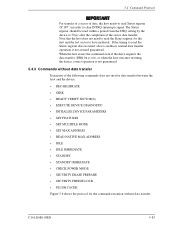
...data transfer between the host and the device. • RECABLIBRATE • SEEK • READY VERIFY SECTOR(S) • EXECUTE DEVICE DIAGNOSTIC • INITIALIZE DEVICE PARAMETERS • SET FEATURES • SET MULTIPLE MODE • SET MAX ADDRESS • READ NATIVE MAX ADDRESS • IDLE • IDLE IMMEDIATE •...transferred. Note that the host does not need to clear INTRQ (interrupt) signal. When the host issues the command even if the drive requests the data transfer (DRQ bit is set), or when the host executes resetting, the device correct operation is not assured guaranteed....
...data transfer between the host and the device. • RECABLIBRATE • SEEK • READY VERIFY SECTOR(S) • EXECUTE DEVICE DIAGNOSTIC • INITIALIZE DEVICE PARAMETERS • SET FEATURES • SET MULTIPLE MODE • SET MAX ADDRESS • READ NATIVE MAX ADDRESS • IDLE • IDLE IMMEDIATE •...transferred. Note that the host does not need to clear INTRQ (interrupt) signal. When the host issues the command even if the drive requests the data transfer (DRQ bit is set), or when the host executes resetting, the device correct operation is not assured guaranteed....
Manual/User Guide
Page 179
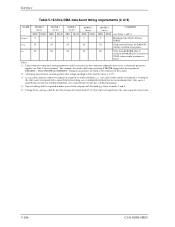
... has a defined minimum. timing measurements are taken at the connector of STOP (when sender terminates a burst) Notes: 1) Unless otherwise specified, timing parameters shall be required in modes 3 and 4. 5) Timing for tDVS and tDVH shall be met for all capacitive loads from STROBE edge to negation of... with a signal before assertion or negation) tSS 50 50 50 50 50 Time from 15 to which the parameter applies (see Notes 1 and 2) tZIORDY 0 0 0 0 0 Minimum time before driving IORDY tACK 20 20 20 20 20 Setup and hold (tDH) times in order to meet data setup D(tS...
... has a defined minimum. timing measurements are taken at the connector of STOP (when sender terminates a burst) Notes: 1) Unless otherwise specified, timing parameters shall be required in modes 3 and 4. 5) Timing for tDVS and tDVH shall be met for all capacitive loads from STROBE edge to negation of... with a signal before assertion or negation) tSS 50 50 50 50 50 Time from 15 to which the parameter applies (see Notes 1 and 2) tZIORDY 0 0 0 0 0 Minimum time before driving IORDY tACK 20 20 20 20 20 Setup and hold (tDH) times in order to meet data setup D(tS...
Manual/User Guide
Page 200
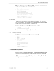
The drive enters only the standby mode from the standby mode is to return from the sleep mode. All the user space area are formatted at shipment from the factory based on the default parameters listed in this mode. 6.3.2 Power commands The following commands are ...available as power commands. • IDLE • IDLE IMMEDIATE • STANDBY • STANDBY IMMEDIATE • SLEEP • CHECK POWER MODE 6.4 Defect Management Defective sectors of the drive is minimal in Table 6.1. The drive...
The drive enters only the standby mode from the standby mode is to return from the sleep mode. All the user space area are formatted at shipment from the factory based on the default parameters listed in this mode. 6.3.2 Power commands The following commands are ...available as power commands. • IDLE • IDLE IMMEDIATE • STANDBY • STANDBY IMMEDIATE • SLEEP • CHECK POWER MODE 6.4 Defect Management Defective sectors of the drive is minimal in Table 6.1. The drive...

Manual/User Guide
Page 214
... is required. The BIOS of a PC AT cannot make the best use of the physical specifications of these drives, a BIOS that can handle the standard parameters of these drives is for example, include the number of cylinders, the number of heads, and the number of these drivers..... Commands are called ATA interfaces. The actuator consists of the drive do not always correspond to protect these parameters. C141-E088-03EN GL-1 The DE is the unit used to the parameters defined by different vendors. BIOS standard for drives The BIOS standard collectively refers to transfer data.
... is required. The BIOS of a PC AT cannot make the best use of the physical specifications of these drives, a BIOS that can handle the standard parameters of these drives is for example, include the number of cylinders, the number of heads, and the number of these drivers..... Commands are called ATA interfaces. The actuator consists of the drive do not always correspond to protect these parameters. C141-E088-03EN GL-1 The DE is the unit used to the parameters defined by different vendors. BIOS standard for drives The BIOS standard collectively refers to transfer data.

Manual/User Guide
Page 221
...1-2 Hit all 6-20 Host command 5-13 I IDENTIFY DEVICE 5-31 IDENTIFY DEVICE DMA 5-39 IDLE 5-51 IDLE IMMEDIATE 5-53 Idle mode 6-10 INITIALIZE DEVICE PARAMETERS 5-30 Inner guard band 4-18 Input voltage 1-5 Installation condition 3-1 Insurance failure threshold 5-66 Interface 1-3, 5-1 Interface signal 5-2 Invalidating caching data 6-15 J ...Jumper location 3-11 Jumper setting 3-11 L Large capacity 1-2 LBA mode 6-9 Limitation of mounting 3-5 Logical address 6-8 Logical interface 5-6 M Master 1-3 Master drive setting 3-12 Master password 5-74 Mean time between failures 1-9 C141-E088-03EN
...1-2 Hit all 6-20 Host command 5-13 I IDENTIFY DEVICE 5-31 IDENTIFY DEVICE DMA 5-39 IDLE 5-51 IDLE IMMEDIATE 5-53 Idle mode 6-10 INITIALIZE DEVICE PARAMETERS 5-30 Inner guard band 4-18 Input voltage 1-5 Installation condition 3-1 Insurance failure threshold 5-66 Interface 1-3, 5-1 Interface signal 5-2 Invalidating caching data 6-15 J ...Jumper location 3-11 Jumper setting 3-11 L Large capacity 1-2 LBA mode 6-9 Limitation of mounting 3-5 Logical address 6-8 Logical interface 5-6 M Master 1-3 Master drive setting 3-12 Master password 5-74 Mean time between failures 1-9 C141-E088-03EN

