Manual/User Guide
Page 20
... in LBA mode) 6-9 Figure 6.7 Sector slip processing 6-12 Figure 6.8 Alternate cylinder assignment 6-13 Figure 6.9 Data buffer configuration 6-14 Table 1.1 Table 1.2 Table 1.3 Table 1.4 Table 1.5 Table 1.6 Specifications 1-4 Model names and product numbers 1-5 Current and power dissipation 1-6 Environmental specifications 1-7 Acoustic noise specification 1-8 Shock and vibration specification 1-8 Table 3.1 Surface temperature measurement points and standard values...
... in LBA mode) 6-9 Figure 6.7 Sector slip processing 6-12 Figure 6.8 Alternate cylinder assignment 6-13 Figure 6.9 Data buffer configuration 6-14 Table 1.1 Table 1.2 Table 1.3 Table 1.4 Table 1.5 Table 1.6 Specifications 1-4 Model names and product numbers 1-5 Current and power dissipation 1-6 Environmental specifications 1-7 Acoustic noise specification 1-8 Shock and vibration specification 1-8 Table 3.1 Surface temperature measurement points and standard values...
Manual/User Guide
Page 26
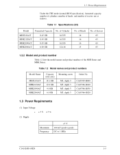
...to 1 MHz C141-E088-03EN 1-5 Table 1.1 Specifications (2/2) Model MHJ2181AT MHK2120AT MHK2090AT MHK2060AT Formatted Capacity 8.45 GB 8.45 GB 8.45 GB 6.00 GB No. of Sectors 63 63 63 63 1.2.2 Model and product number Table 1.2 lists the model names and product numbers of Heads 16 16 16 15 No.... of sectors are as follows. Table 1.2 Model names and product numbers Model Name MHJ2181AT MHK2120AT MHK2090AT MHK2060AT Capacity (user area) 18.1 GB 12.0 GB 9.0 GB 6.0 GB Mounting screw Order No. 1.3 Power Requirements Under the CHS mode (normal BIOS specification...
...to 1 MHz C141-E088-03EN 1-5 Table 1.1 Specifications (2/2) Model MHJ2181AT MHK2120AT MHK2090AT MHK2060AT Formatted Capacity 8.45 GB 8.45 GB 8.45 GB 6.00 GB No. of Sectors 63 63 63 63 1.2.2 Model and product number Table 1.2 lists the model names and product numbers of Heads 16 16 16 15 No.... of sectors are as follows. Table 1.2 Model names and product numbers Model Name MHJ2181AT MHK2120AT MHK2090AT MHK2060AT Capacity (user area) 18.1 GB 12.0 GB 9.0 GB 6.0 GB Mounting screw Order No. 1.3 Power Requirements Under the CHS mode (normal BIOS specification...
Manual/User Guide
Page 33
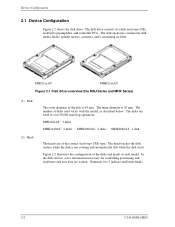
... 2.1 Device Configuration Figure 2.1 shows the disk drive. The inner diameter is not rotating and automatically lifts when the disk starts. MHJ2181AT: 3 disks MHK2120AT: 2 disks MHK2090AT: 2 disks MHK2060AT: 1 disk The heads are of disks used varies with the model, as described below. Numerals 0 to 5 ...disks and heads of the disk is 65 mm. MHJ21xxAT MHK2xxxAT Figure 2.1 Disk drive outerview (the MHJ Series and MHK Series) (1) Disk (2) Head The outer diameter of each model. In the disk surface, servo information necessary for controlling positioning and read/write...
... 2.1 Device Configuration Figure 2.1 shows the disk drive. The inner diameter is not rotating and automatically lifts when the disk starts. MHJ2181AT: 3 disks MHK2120AT: 2 disks MHK2090AT: 2 disks MHK2060AT: 1 disk The heads are of disks used varies with the model, as described below. Numerals 0 to 5 ...disks and heads of the disk is 65 mm. MHJ21xxAT MHK2xxxAT Figure 2.1 Disk drive outerview (the MHJ Series and MHK Series) (1) Disk (2) Head The outer diameter of each model. In the disk surface, servo information necessary for controlling positioning and read/write...
Manual/User Guide
Page 47
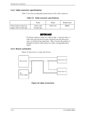
... 3.8 Cable connections 3-10 C141-E088-03EN Table 3.2 Cable connector specifications ATA interface and power supply cable (44-pin type) Name Cable socket (44-pin type) Model 89361-144 Manufacturer BERG For the host interface cable, use a ribbon cable. A twisted cable or a cable with wires that have become separated from the ribbon...
... 3.8 Cable connections 3-10 C141-E088-03EN Table 3.2 Cable connector specifications ATA interface and power supply cable (44-pin type) Name Cable socket (44-pin type) Model 89361-144 Manufacturer BERG For the host interface cable, use a ribbon cable. A twisted cable or a cable with wires that have become separated from the ribbon...

Manual/User Guide
Page 106
...' X'0007' (Variable) (Variable) (Variable) (Variable) *6 *2 X'0000' X'xx07' X'0003' X'0078' X'0078' X'00F0' X'0078' X'0000' X'003C' X'0000' X'346B' X'4008' X'4000' Description Firmware revision (ASCII code, 8 characters, left) Model name (ASCII code, 40 characters, left) Maximum number of sectors per interrupt on READ/WRITE MULTIPLE command Reserved Capabilities *3 Reserved PIO data transfer mode *4 Reserved...
...' X'0007' (Variable) (Variable) (Variable) (Variable) *6 *2 X'0000' X'xx07' X'0003' X'0078' X'0078' X'00F0' X'0078' X'0000' X'003C' X'0000' X'346B' X'4008' X'4000' Description Firmware revision (ASCII code, 8 characters, left) Model name (ASCII code, 40 characters, left) Maximum number of sectors per interrupt on READ/WRITE MULTIPLE command Reserved Capabilities *3 Reserved PIO data transfer mode *4 Reserved...

Manual/User Guide
Page 222
Mean time to repair 1-9 Media defect 1-10 Microprocessor unit 4-14 Mis-hit 6-16 Model and product number 1-5 Model name and product number 1-5 Mounting 3-4 Move head to reference cylinder 4-15 MPU 4-14 MTBF 1-9 MTTR 1-9 Multiword DMA data transfer timing 5-103 Multiword mode 2 2-4 N NIEN 5-13 ...
Mean time to repair 1-9 Media defect 1-10 Microprocessor unit 4-14 Mis-hit 6-16 Model and product number 1-5 Model name and product number 1-5 Mounting 3-4 Move head to reference cylinder 4-15 MPU 4-14 MTBF 1-9 MTTR 1-9 Multiword DMA data transfer timing 5-103 Multiword mode 2 2-4 N NIEN 5-13 ...

