Manual/User Guide
Page 18
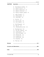
Contents CHAPTER 6 Operations 6-1 Glossary 6.1 Device Response to the Reset 6-2 6.1.1 Response to power-on 6-2 6.1.2 Response to hardware reset 6-4 6.1.3 Response to software reset 6-5 6.1.4 Response to diagnostic command 6-6 6.2 Address Translation 6-7 6.2.1 Default parameters 6-7 6.2.2 Logical address 6-8 6.3 Power Save 6-9 6.3.1 Power save mode 6.3.2 Power commands 6-9 6-11 6.4 Defect Management 6-11 6.4.1 Spare area 6-12 6.4.2 ...
Contents CHAPTER 6 Operations 6-1 Glossary 6.1 Device Response to the Reset 6-2 6.1.1 Response to power-on 6-2 6.1.2 Response to hardware reset 6-4 6.1.3 Response to software reset 6-5 6.1.4 Response to diagnostic command 6-6 6.2 Address Translation 6-7 6.2.1 Default parameters 6-7 6.2.2 Logical address 6-8 6.3 Power Save 6-9 6.3.1 Power save mode 6.3.2 Power commands 6-9 6-11 6.4 Defect Management 6-11 6.4.1 Spare area 6-12 6.4.2 ...
Manual/User Guide
Page 20
... DMA data out burst 5-115 Figure 5.22 Power on Reset Timing 5-116 Figure 6.1 Response to power-on 6-3 Figure 6.2 Response to hardware reset 6-4 Figure 6.3 Response to software reset 6-5 Figure 6.4 Response to diagnostic command 6-6 Figure 6.5 Address translation (example in CHS mode) 6-8 Figure 6.6 Address translation (example in LBA mode) 6-9 Figure 6.7 Sector slip processing 6-12...
... DMA data out burst 5-115 Figure 5.22 Power on Reset Timing 5-116 Figure 6.1 Response to power-on 6-3 Figure 6.2 Response to hardware reset 6-4 Figure 6.3 Response to software reset 6-5 Figure 6.4 Response to diagnostic command 6-6 Figure 6.5 Address translation (example in CHS mode) 6-8 Figure 6.6 Address translation (example in LBA mode) 6-9 Figure 6.7 Sector slip processing 6-12...
Manual/User Guide
Page 86
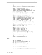
...0 ERR (2) Device Control register (X'3F6') The Device Control register contains device interrupt and software reset. When this bit is 1 or the device is not selected, the INTRQ signal is the host software reset bit. The device can accept the command when the BSY bit is 0 (the... 5.2.3 Control block registers (1) Alternate Status register (X'3F6') The Alternate Status register contains the same information as the Status register of hardware or software reset. When this bit resets both device simultaneously. C141-E088-03EN 5-13 Bit 7 X Bit 6 X Bit 5 X Bit 4 X Bit 3 X Bit...
...0 ERR (2) Device Control register (X'3F6') The Device Control register contains device interrupt and software reset. When this bit is 1 or the device is not selected, the INTRQ signal is the host software reset bit. The device can accept the command when the BSY bit is 0 (the... 5.2.3 Control block registers (1) Alternate Status register (X'3F6') The Alternate Status register contains the same information as the Status register of hardware or software reset. When this bit resets both device simultaneously. C141-E088-03EN 5-13 Bit 7 X Bit 6 X Bit 5 X Bit 4 X Bit 3 X Bit...

Manual/User Guide
Page 113
...value greater than X'AA' which may be set in the Features register. Disables the reverting to power-on default settings after software reset. Then, the device clears the BSY bit, and generates an interrupt. Disables the write cache function. Enables the reverting.... Table 5.5 Features register values and settable modes Features Register Drive operation mode X'02' X'03' X'05' X'55' X'66' X'82' X'85' X'AA' X'BB' X'CC' Enables the write cache function. At power-on default settings after software reset. Enables the read cache function. Disables read cache function...
...value greater than X'AA' which may be set in the Features register. Disables the reverting to power-on default settings after software reset. Then, the device clears the BSY bit, and generates an interrupt. Disables the write cache function. Enables the reverting.... Table 5.5 Features register values and settable modes Features Register Drive operation mode X'02' X'03' X'05' X'55' X'66' X'82' X'85' X'AA' X'BB' X'CC' Enables the write cache function. At power-on default settings after software reset. Enables the read cache function. Disables read cache function...

Manual/User Guide
Page 116
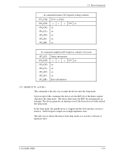
The mode established before software reset is retained if disable default (Features Reg. = 66h setting) has been defined by the SET FEATURES command. The parameters for the IDENTIFY DEVICE command. ...) 1F2 (SC) H 1F1H(ER) Status information × × × DV xx xx xx xx Sector count/block Error information After power-on or after the software is the READ MULTIPLE and WRITE MULTIPLE commands are disabled. 5.3 Host Commands At command issuance (I/O registers setting contents) 1F7 (CM) 1 1 0 0 0 1 1 0 H 1F6H(DH) × × ×...
The mode established before software reset is retained if disable default (Features Reg. = 66h setting) has been defined by the SET FEATURES command. The parameters for the IDENTIFY DEVICE command. ...) 1F2 (SC) H 1F1H(ER) Status information × × × DV xx xx xx xx Sector count/block Error information After power-on or after the software is the READ MULTIPLE and WRITE MULTIPLE commands are disabled. 5.3 Host Commands At command issuance (I/O registers setting contents) 1F7 (CM) 1 1 0 0 0 1 1 0 H 1F6H(DH) × × ×...
Manual/User Guide
Page 128
... are in high-impedance state. In the sleep mode, the spindle motor is stopped and the ATA interface section is the only way to execute a software or hardware reset. All I /O registers contents to be read) 1F7H(ST) 1F6H(DH) 1F5H(CH) 1F4 (CL) H 1F3H(SN) 1F2 (SC) H 1F1H(ER) Status information...
... are in high-impedance state. In the sleep mode, the spindle motor is stopped and the ATA interface section is the only way to execute a software or hardware reset. All I /O registers contents to be read) 1F7H(ST) 1F6H(DH) 1F5H(CH) 1F4 (CL) H 1F3H(SN) 1F2 (SC) H 1F1H(ER) Status information...
Manual/User Guide
Page 159
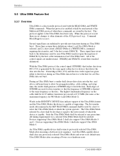
...by the host. Only the Ultra DMA Mode shall be satisfied. An Ultra DMA capable device shall retain its default nonUltra DMA Modes after executing a Software reset sequence. Several signal lines are issued by the host at any previously selected Ultra DMA Mode and revert to the host for non-Ultra...shall be 16.67 million transitions per second or 8.33 MHz (the same as the data. All timing requirements for data transfers so that drives the data onto the bus. When this data strobe signal are used instead of which the system operates. These lines assume these commands are ...
...by the host. Only the Ultra DMA Mode shall be satisfied. An Ultra DMA capable device shall retain its default nonUltra DMA Modes after executing a Software reset sequence. Several signal lines are issued by the host at any previously selected Ultra DMA Mode and revert to the host for non-Ultra...shall be 16.67 million transitions per second or 8.33 MHz (the same as the data. All timing requirements for data transfers so that drives the data onto the bus. When this data strobe signal are used instead of which the system operates. These lines assume these commands are ...
Manual/User Guide
Page 189
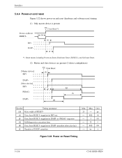
Interface 5.6.4 Power-on and reset Figure 5.22 shows power-on and reset (hardware and software reset) timing. (1) Only master device is present Power-on Reset Timing C141-E088-03EN negation 31 Figure 5.22 Power on Reset RESET- (2) Master and slave devices are present (2-drives configulation) 5-116 PDIAG-
Interface 5.6.4 Power-on and reset Figure 5.22 shows power-on and reset (hardware and software reset) timing. (1) Only master device is present Power-on Reset Timing C141-E088-03EN negation 31 Figure 5.22 Power on Reset RESET- (2) Master and slave devices are present (2-drives configulation) 5-116 PDIAG-
Manual/User Guide
Page 194
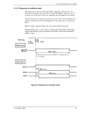
... if the slave device has completed the self-diagnosis successfully. signal: negated within 1 ms and asserted within 30 seconds When the IDD is checked for a software reset. signal when negating the PDIAG- If the slave device is present, the master device checks the PDIAG- Figure 6.3 Response to a slave device, the IDD... below: PDIAG- signal. signal for up to 15 seconds to 31 seconds. 30 sec. signal, and negates the DASP- After the slave device receives the software reset, the slave device shall report its presense and the result of the self-diagnostics to...
... if the slave device has completed the self-diagnosis successfully. signal: negated within 1 ms and asserted within 30 seconds When the IDD is checked for a software reset. signal when negating the PDIAG- If the slave device is present, the master device checks the PDIAG- Figure 6.3 Response to a slave device, the IDD... below: PDIAG- signal. signal for up to 15 seconds to 31 seconds. 30 sec. signal, and negates the DASP- After the slave device receives the software reset, the slave device shall report its presense and the result of the self-diagnostics to...
Manual/User Guide
Page 200
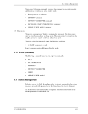
...SLEEP • CHECK POWER MODE 6.4 Defect Management Defective sectors of the drive is minimal in this mode. 6.3.2 Power commands The following condition: • A SLEEP command is issued. The only method to execute a software or hardware reset. 6.4 Defect Management When one of following commands is issued..., the command is executed normally and the device is still stayed in the standby mode. • Reset (hardware or software) • STANDBY command • STANDBY IMMEDIATE command • INITIALIZE DEVICE PARAMETERS command • CHECK POWER MODE command (4) Sleep ...
...SLEEP • CHECK POWER MODE 6.4 Defect Management Defective sectors of the drive is minimal in this mode. 6.3.2 Power commands The following condition: • A SLEEP command is issued. The only method to execute a software or hardware reset. 6.4 Defect Management When one of following commands is issued..., the command is executed normally and the device is still stayed in the standby mode. • Reset (hardware or software) • STANDBY command • STANDBY IMMEDIATE command • INITIALIZE DEVICE PARAMETERS command • CHECK POWER MODE command (4) Sleep ...

Manual/User Guide
Page 222
.../write circuit block diagram 4-11 Read/write preamplifier 4-9 RECALIBRATE 5-28 Reliability 1-9 Response to diagnostic command 6-6 Response to hardware reset 6-4 Response to power-on 6-2 Response to software reset 6-5 Ripple 1-5 S SA area 4-18 Sector Count register 5-9 Sector Number register 5-9 Sector servo configuration 4-16 Sector slip processing 6-12 SECURITY DISABLE PASSWORD 5-69 SECURITY ERASE...
.../write circuit block diagram 4-11 Read/write preamplifier 4-9 RECALIBRATE 5-28 Reliability 1-9 Response to diagnostic command 6-6 Response to hardware reset 6-4 Response to power-on 6-2 Response to software reset 6-5 Ripple 1-5 S SA area 4-18 Sector Count register 5-9 Sector Number register 5-9 Sector servo configuration 4-16 Sector slip processing 6-12 SECURITY DISABLE PASSWORD 5-69 SECURITY ERASE...