Manual/User Guide
Page 1
CHAPTER 3 Installation Conditions 3.1 Dimensions 3.2 Mounting 3.3 Connections with Host System This chapter gives the external dimensions, installation conditions, surface temperature conditions, cable connections, and switch settings of the hard disk drives. C141-E262 3-1
CHAPTER 3 Installation Conditions 3.1 Dimensions 3.2 Mounting 3.3 Connections with Host System This chapter gives the external dimensions, installation conditions, surface temperature conditions, cable connections, and switch settings of the hard disk drives. C141-E262 3-1
Manual/User Guide
Page 2
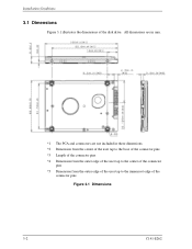
All dimensions are in mm. *1 The PCA and connectors are not included in these dimensions. *2 Dimension from the center of the user tap to the base of the connector pins *3 Length of the connector pins *4 Dimension from the outer edge of the user tap to the center of the connector pins *5 Dimension from the outer edge of the user tap to the innermost edge of the disk drive. Installation Conditions 3.1 Dimensions Figure 3.1 illustrates the dimensions of the connector pins Figure 3.1 Dimensions 3-2 C141-E262
All dimensions are in mm. *1 The PCA and connectors are not included in these dimensions. *2 Dimension from the center of the user tap to the base of the connector pins *3 Length of the connector pins *4 Dimension from the outer edge of the user tap to the center of the connector pins *5 Dimension from the outer edge of the user tap to the innermost edge of the disk drive. Installation Conditions 3.1 Dimensions Figure 3.1 illustrates the dimensions of the connector pins Figure 3.1 Dimensions 3-2 C141-E262
Manual/User Guide
Page 3
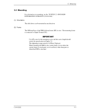
... length should satisfy the specification in any direction. (2) Frame The MR head bias of the HDD disk enclosure (DE) is attached. The mounting frame is connected to which the HDD is zero. The tightening torque must be mounted in Figure 3.2. 3.2 Mounting 3.2 Mounting For information on mounting, see the "FUJITSU 2.5-INCH HDD INTEGRATION GUIDANCE (C141-E144)." (1) Orientation The disk drives can be 0.49N...
... length should satisfy the specification in any direction. (2) Frame The MR head bias of the HDD disk enclosure (DE) is attached. The mounting frame is connected to which the HDD is zero. The tightening torque must be mounted in Figure 3.2. 3.2 Mounting 3.2 Mounting For information on mounting, see the "FUJITSU 2.5-INCH HDD INTEGRATION GUIDANCE (C141-E144)." (1) Orientation The disk drives can be 0.49N...
Manual/User Guide
Page 4
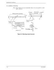
Installation Conditions (3) Limitation of A 3.0 or less Screw Figure 3.2 Mounting frame structure 3-4 C141-E262 Bottom surface mounting DE 2 A Frame of system cabinet 2.5 2.5 2.5 Side surface 2.5 mounting PCA B Frame of system cabinet 3.0 or less Screw Details of mounting Note) These dimensions are recommended values; if it is not possible to satisfy them, contact us.
Installation Conditions (3) Limitation of A 3.0 or less Screw Figure 3.2 Mounting frame structure 3-4 C141-E262 Bottom surface mounting DE 2 A Frame of system cabinet 2.5 2.5 2.5 Side surface 2.5 mounting PCA B Frame of system cabinet 3.0 or less Screw Details of mounting Note) These dimensions are recommended values; if it is not possible to satisfy them, contact us.
Manual/User Guide
Page 5
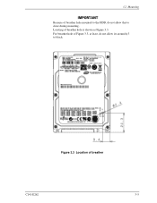
For breather hole of Figure 3.3, at least, do not allow its around φ 3 to close during mounting. 3.2 Mounting Because of breather hole mounted to the HDD, do not allow this to block. Locating of breather C141-E262 3-5 Figure 3.3 Location of breather hole is shown as Figure 3.3.
For breather hole of Figure 3.3, at least, do not allow its around φ 3 to close during mounting. 3.2 Mounting Because of breather hole mounted to the HDD, do not allow this to block. Locating of breather C141-E262 3-5 Figure 3.3 Location of breather hole is shown as Figure 3.3.
Manual/User Guide
Page 6
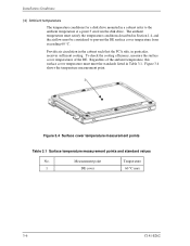
...Temperature 1 DE cover 60 °C max 3-6 C141-E262 To check the cooling efficiency, measure the surface cover temperatures of the ambient temperature, this surface cover temperature must be considered to the ambient temperature at a point 3 cm from exceeding 60 °C. The ambient temperature must satisfy the temperature... temperature measurement point. 1 Figure 3.4 Surface cover temperature measurement points Table 3.1 Surface temperature measurement points and standard values No. Installation Conditions (4) Ambient temperature The temperature conditions for a disk drive ...
...Temperature 1 DE cover 60 °C max 3-6 C141-E262 To check the cooling efficiency, measure the surface cover temperatures of the ambient temperature, this surface cover temperature must be considered to the ambient temperature at a point 3 cm from exceeding 60 °C. The ambient temperature must satisfy the temperature... temperature measurement point. 1 Figure 3.4 Surface cover temperature measurement points Table 3.1 Surface temperature measurement points and standard values No. Installation Conditions (4) Ambient temperature The temperature conditions for a disk drive ...
Manual/User Guide
Page 7
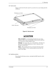
... hard, the cover and the spindle motor contact, which may cause damage to the disk drive. Pressing it by external magnetic fields. Static: When handling the device, disconnect the body ground (500 kΩ or greater). 3.2 Mounting (5) Service area Figure 3.5 shows how the drive must be accessed (service areas) during and after installation. Mounting screw hole Cable connection Mounting screw hole Figure 3.5 Service area Data...
... hard, the cover and the spindle motor contact, which may cause damage to the disk drive. Pressing it by external magnetic fields. Static: When handling the device, disconnect the body ground (500 kΩ or greater). 3.2 Mounting (5) Service area Figure 3.5 shows how the drive must be accessed (service areas) during and after installation. Mounting screw hole Cable connection Mounting screw hole Figure 3.5 Service area Data...
Manual/User Guide
Page 8
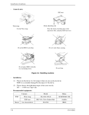
... absorbing mat on the operation table, and place ESD mat on it. HDD is occasionally damaged by the impact of the driver. (2) Please observe the tightening torque of a low impact when you use an electric driver. Installation Conditions - Figure 3.6 Handling cautions - Recommended equipments ESD Shock Contents Wrist strap ESD mat Low shock driver Model JX-1200-3056-8 SKY...
... absorbing mat on the operation table, and place ESD mat on it. HDD is occasionally damaged by the impact of the driver. (2) Please observe the tightening torque of a low impact when you use an electric driver. Installation Conditions - Figure 3.6 Handling cautions - Recommended equipments ESD Shock Contents Wrist strap ESD mat Low shock driver Model JX-1200-3056-8 SKY...
Manual/User Guide
Page 9
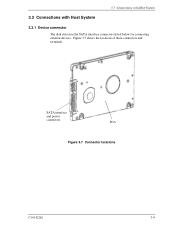
Figure 3.7 shows the locations of these connectors and terminals. 3.3 Connections with Host System 3.3 Connections with Host System 3.3.1 Device connector The disk drive has the SATA interface connectors listed below for connecting external devices. SATA interface and power connectors PCA Figure 3.7 Connector locations C141-E262 3-9
Figure 3.7 shows the locations of these connectors and terminals. 3.3 Connections with Host System 3.3 Connections with Host System 3.3.1 Device connector The disk drive has the SATA interface connectors listed below for connecting external devices. SATA interface and power connectors PCA Figure 3.7 Connector locations C141-E262 3-9
Manual/User Guide
Page 10
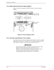
... connector of the connection with Serial-ATA Revision 2.5 specification. Therefore, we recommend that the customer evaluate the connector on the customer's system and select it from the PCA side Figure 3.8 Power supply pins (CN1) 3.3.3 Connector specifications for mating with the disk drive must be compliant with the host system. Installation Conditions 3.3.2 Signal segment and power supply segment Figure 3.8 shows each segment of requirements about SATA interface connector, refer to the "Serial-ATA...
... connector of the connection with Serial-ATA Revision 2.5 specification. Therefore, we recommend that the customer evaluate the connector on the customer's system and select it from the PCA side Figure 3.8 Power supply pins (CN1) 3.3.3 Connector specifications for mating with the disk drive must be compliant with the host system. Installation Conditions 3.3.2 Signal segment and power supply segment Figure 3.8 shows each segment of requirements about SATA interface connector, refer to the "Serial-ATA...
Manual/User Guide
Page 11
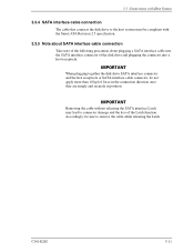
... the Serial ATA Revision 2.5 specification. 3.3.5 Note about SATA interface cable connection Take note of the following precaution about plugging a SATA interface cable into the SATA interface connector of the disk drive and plugging the connector into a host receptacle: When plugging together the disk drive SATA interface connector and the host receptacle or SATA interface cable connector, do not apply more than 10 kgf of the Latch function. C141-E262 3-11 Removing the cable without releasing the SATA interface Latch...
... the Serial ATA Revision 2.5 specification. 3.3.5 Note about SATA interface cable connection Take note of the following precaution about plugging a SATA interface cable into the SATA interface connector of the disk drive and plugging the connector into a host receptacle: When plugging together the disk drive SATA interface connector and the host receptacle or SATA interface cable connector, do not apply more than 10 kgf of the Latch function. C141-E262 3-11 Removing the cable without releasing the SATA interface Latch...


