Maintenance Manual
Page 64
...circuit and DAC system. Theory of Device Operation 4.5 Self-calibration The disk drive occasionally performs self-calibration in order to the FPC forces and winds accompanying disk revolution. The firmware of the drive measures and stores the force (value of the whole servo system due to...servo control is positioned. The forces are occasionally sensed. The torque varies with the disk drive and the cylinder where the head is realized. 4-8 C141-E293 For sensing, the firmware mixes the disturbance signal to the position signal at factory calibration. For compensating, the ...
...circuit and DAC system. Theory of Device Operation 4.5 Self-calibration The disk drive occasionally performs self-calibration in order to the FPC forces and winds accompanying disk revolution. The firmware of the drive measures and stores the force (value of the whole servo system due to...servo control is positioned. The forces are occasionally sensed. The torque varies with the disk drive and the cylinder where the head is realized. 4-8 C141-E293 For sensing, the firmware mixes the disturbance signal to the position signal at factory calibration. For compensating, the ...
Maintenance Manual
Page 73
...data zone in the data area. The MPU calculates the difference (speed error) between the target position and the position clarified by the firmware. The calculation is loaded on the data surface. For each sampling timing during head movement to the disk. The reference cylinder is ...of media to press the head against the outer direction. The MPU then feeds the VCM drive current by the firmware. C141-E293 4-17 The servo control of sampling time, executes calculation, and updates the VCM drive current. c) When the servo mark is detected the head is turned. 4.7 Servo Control...
...data zone in the data area. The MPU calculates the difference (speed error) between the target position and the position clarified by the firmware. The calculation is loaded on the data surface. For each sampling timing during head movement to the disk. The reference cylinder is ...of media to press the head against the outer direction. The MPU then feeds the VCM drive current by the firmware. C141-E293 4-17 The servo control of sampling time, executes calculation, and updates the VCM drive current. c) When the servo mark is detected the head is turned. 4.7 Servo Control...
Maintenance Manual
Page 74
...electromotive force. e) The MPU is controlled by sending several signals including the serial data from the beginning. The SVC starts a phase switching by Fujitsu. The spindle motor is waiting for a PHASE signal. It moves to 3) or 5) step depending on the PHASE signal from PHASE signal. ...(3) Stable rotation mode The SVC builds the PLL circuit into, and to the MPU using a PHASE signal for the spindle control; And the firmware observes an abnormal rotation. 4-18 C141-E293 Whereas, it moves to the step 5). When a PHASE signal is treated as the free-wheeling ...
...electromotive force. e) The MPU is controlled by sending several signals including the serial data from the beginning. The SVC starts a phase switching by Fujitsu. The spindle motor is waiting for a PHASE signal. It moves to 3) or 5) step depending on the PHASE signal from PHASE signal. ...(3) Stable rotation mode The SVC builds the PLL circuit into, and to the MPU using a PHASE signal for the spindle control; And the firmware observes an abnormal rotation. 4-18 C141-E293 Whereas, it moves to the step 5). When a PHASE signal is treated as the free-wheeling ...
Maintenance Manual
Page 117
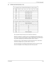
When this command is accepted, the device does beginning the data transfer of the device (firmware). Refer to Table 5.7. In the data transfer of Subcommand code 01h and 03h transfer by Subcommand code 07h, reactivates in the device for the update ...
When this command is accepted, the device does beginning the data transfer of the device (firmware). Refer to Table 5.7. In the data transfer of Subcommand code 01h and 03h transfer by Subcommand code 07h, reactivates in the device for the update ...
Maintenance Manual
Page 119
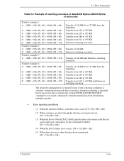
...from 384 to 511 KB Transfer from 512 to 639 KB Firmware rewriting execution Transfer of 640 KB Firmware rewriting execution Transfer of 640 KB and Firmware rewriting execution Transfer of 128 KB (0 to 127 KB) ...Transfer from 384 to 511 KB Transfer from 512 to 639 KB and Firmware rewriting execution The Aborted Command error is reported if any of the following conditions is satisfied: ...transferred microcode data is incorrect, firmware rewriting is specified before microcode data is transferred, or the DOWNLOAD MICROCODE command is not...
...from 384 to 511 KB Transfer from 512 to 639 KB Firmware rewriting execution Transfer of 640 KB Firmware rewriting execution Transfer of 640 KB and Firmware rewriting execution Transfer of 128 KB (0 to 127 KB) ...Transfer from 384 to 511 KB Transfer from 512 to 639 KB and Firmware rewriting execution The Aborted Command error is reported if any of the following conditions is satisfied: ...transferred microcode data is incorrect, firmware rewriting is specified before microcode data is transferred, or the DOWNLOAD MICROCODE command is not...
Maintenance Manual
Page 179
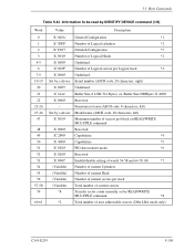
... *3 X '0010' Number of Logical Heads *2 X '0000' Undefined X '003F' Number of user addressable sectors (28bit LBA mode only) C141-E293 5-105 Buffer Size=8MBytes: X '4000' Reserved Firmware revision (ASCII code, 8 characters, left) Model name (ASCII code, 40 characters, left) Maximum number of sectors per block on READ/WRITE MULTIPLE command Reserved Capabilities...
... *3 X '0010' Number of Logical Heads *2 X '0000' Undefined X '003F' Number of user addressable sectors (28bit LBA mode only) C141-E293 5-105 Buffer Size=8MBytes: X '4000' Reserved Firmware revision (ASCII code, 8 characters, left) Model name (ASCII code, 40 characters, left) Maximum number of sectors per block on READ/WRITE MULTIPLE command Reserved Capabilities...
Maintenance Manual
Page 290
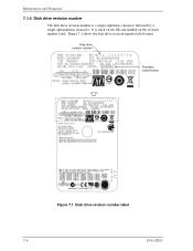
It is a single alphabetic character followed by a single alphanumeric character. Maintenance and Diagnosis 7.1.4 Disk drive revision number The disk drive revision number is stuck on the DE and marked on the revision number label. Figure 7.1 shows the disk drive revision number label format. Disk drive revision number Firmware code/revision Figure 7.1 Disk drive revision number label 7-6 C141-E293
It is a single alphabetic character followed by a single alphanumeric character. Maintenance and Diagnosis 7.1.4 Disk drive revision number The disk drive revision number is stuck on the DE and marked on the revision number label. Figure 7.1 shows the disk drive revision number label format. Disk drive revision number Firmware code/revision Figure 7.1 Disk drive revision number label 7-6 C141-E293
Maintenance Manual
Page 291
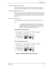
...row using = marks (see Figure 7.2). (3) Firmware code and revision First 4-digit indicates a firmware code and rest 4-digit indicates its revision. Note: For a change of revision number after delivery, Fujitsu issues a "Change Request/Notice" and the disk drive revision number after the change in the relevant ..., the machine revision number may need to the relevant number in the field A3 Revision Figure 7.2 Display of disk drive revision number C141-E293 7-7 7.1 Maintenance (1) Revision number marking at the user site, the revision number level should be changed as ...
...row using = marks (see Figure 7.2). (3) Firmware code and revision First 4-digit indicates a firmware code and rest 4-digit indicates its revision. Note: For a change of revision number after delivery, Fujitsu issues a "Change Request/Notice" and the disk drive revision number after the change in the relevant ..., the machine revision number may need to the relevant number in the field A3 Revision Figure 7.2 Display of disk drive revision number C141-E293 7-7 7.1 Maintenance (1) Revision number marking at the user site, the revision number level should be changed as ...


