
Maintenance Manual
Page 15
...(S) (X '30' or X '31 5-34 (4) WRITE VERIFY (X '3C 5-36 (5) READ VERIFY SECTOR(S) (X '40' or X '41 5-38 (6) SEEK (X '70' to X '7F 5-40 (7) EXECUTE DEVICE DIAGNOSTIC (X '90 5-41 (8) INITIALIZE DEVICE PARAMETERS (X '91 5-42 C141-E293 xi
...(S) (X '30' or X '31 5-34 (4) WRITE VERIFY (X '3C 5-36 (5) READ VERIFY SECTOR(S) (X '40' or X '41 5-38 (6) SEEK (X '70' to X '7F 5-40 (7) EXECUTE DEVICE DIAGNOSTIC (X '90 5-41 (8) INITIALIZE DEVICE PARAMETERS (X '91 5-42 C141-E293 xi

Maintenance Manual
Page 34
...external factors, such as follows: Total operation time in all fields MTBF= (H) number of device failure in all fields (*1) *1 "Disk drive defects" refers to repair (MTTR) is 30 minutes or less, if repaired by a specialist maintenance staff member. (3) Service life In ...surface temperature. This does not include power supply abnormalities during disk media initialization (formatting) or processing of operation, whichever occurs first. When the DE surface temperature exceeds 48 °C, the disk drives require no overhaul for the measurement point of any power supply abnormalities....
...external factors, such as follows: Total operation time in all fields MTBF= (H) number of device failure in all fields (*1) *1 "Disk drive defects" refers to repair (MTTR) is 30 minutes or less, if repaired by a specialist maintenance staff member. (3) Service life In ...surface temperature. This does not include power supply abnormalities during disk media initialization (formatting) or processing of operation, whichever occurs first. When the DE surface temperature exceeds 48 °C, the disk drives require no overhaul for the measurement point of any power supply abnormalities....

Maintenance Manual
Page 37
...-1, which is initialized to Mode-1 (default value) at power-off. Table 1.7 Advanced Power Management APM Mode Mode-0 Mode-1 Mode-2 Active Idle (VCM Lock) 0.2-1.2 sec 0.1-0.2 sec 0.1-0.2 sec Low Power Idle (Unload) 15 min. 10.0-27.5 sec 10.0-27.5 sec Standby (Spin Off) N/A N/A 10.0-40.0 sec When the maximum time that the drive becomes...
...-1, which is initialized to Mode-1 (default value) at power-off. Table 1.7 Advanced Power Management APM Mode Mode-0 Mode-1 Mode-2 Active Idle (VCM Lock) 0.2-1.2 sec 0.1-0.2 sec 0.1-0.2 sec Low Power Idle (Unload) 15 min. 10.0-27.5 sec 10.0-27.5 sec Standby (Spin Off) N/A N/A 10.0-40.0 sec When the maximum time that the drive becomes...

Maintenance Manual
Page 38
As requested by the host, the disk drive switches its I/F power state from the Active state to the Partial state, or from the Active state to the Slumber state. 1.12.2 Device-initiated interface power management (DIPM) If this function is enabled by the host. I/F power states 1) Active state ... the Slumber mode. Because the return time to host. Device Overview 1.12 Interface Power Management (IPM) 1.12.1 Host-initiated interface power management (HIPM) When the disk drive is waiting for commands, it can be sent and received. 2) Partial state The SATA interface is in the Power Down state....
As requested by the host, the disk drive switches its I/F power state from the Active state to the Partial state, or from the Active state to the Slumber state. 1.12.2 Device-initiated interface power management (DIPM) If this function is enabled by the host. I/F power states 1) Active state ... the Slumber mode. Because the return time to host. Device Overview 1.12 Interface Power Management (IPM) 1.12.1 Host-initiated interface power management (HIPM) When the disk drive is waiting for commands, it can be sent and received. 2) Partial state The SATA interface is in the Power Down state....

Maintenance Manual
Page 62
... -calibration. Theory of Device Operation 4.4 Power-on Sequence Figure 4.3 describes the operation sequence of the disk drive at power-on , the disk drive initializes its SATA interface block. c) The disk drive executes self-diagnosis (data buffer read /write test. The outline is loaded on the disk. a) After ...applied to the actuator, and updates the calibrating value. 4-6 C141-E293 When the self-diagnosis terminates successfully, the disk drive starts the spindle motor. d) After confirming that the spindle motor has reached rated speed, the head assembly is described below. e) ...
... -calibration. Theory of Device Operation 4.4 Power-on Sequence Figure 4.3 describes the operation sequence of the disk drive at power-on , the disk drive initializes its SATA interface block. c) The disk drive executes self-diagnosis (data buffer read /write test. The outline is loaded on the disk. a) After ...applied to the actuator, and updates the calibrating value. 4-6 C141-E293 When the self-diagnosis terminates successfully, the disk drive starts the spindle motor. d) After confirming that the spindle motor has reached rated speed, the head assembly is described below. e) ...

Maintenance Manual
Page 63
c) Self-diagnosis 2 - Work RAM write/read out of system information f) Drive ready state (command waiting state) g) Execute self-calibration End Figure 4.3 Power-on operation sequence C141-E293 4-7 4.4 Power-on Sequence Power-on -track and read test The spindle motor starts. MPU bus test - Data buffer write/read test d) Confirming spindle motor speed Load the head assembly e) Initial on Start a) SATA I/F Initialization b) Self-diagnosis 1 - Internal register write/read test -
c) Self-diagnosis 2 - Work RAM write/read out of system information f) Drive ready state (command waiting state) g) Execute self-calibration End Figure 4.3 Power-on operation sequence C141-E293 4-7 4.4 Power-on Sequence Power-on -track and read test The spindle motor starts. MPU bus test - Data buffer write/read test d) Confirming spindle motor speed Load the head assembly e) Initial on Start a) SATA I/F Initialization b) Self-diagnosis 1 - Internal register write/read test -

Maintenance Manual
Page 69
b. c. From the servo area on the data surface. The logical initial cylinder is sent to the power amplifier. (4) Power amplifier The power amplifier feeds currents, corresponding to the DAC output signal voltage to the VCM. (5) Spindle ... executes startup of the MPU are output as position information. (3) D/A converter (DAC) The control program calculates the specified data value (digital value) of the VCM drive current, and the value is converted from digital-to position the head at the outermost circumference (cylinder 0). The main internal operations of the spindle motor...
b. c. From the servo area on the data surface. The logical initial cylinder is sent to the power amplifier. (4) Power amplifier The power amplifier feeds currents, corresponding to the DAC output signal voltage to the VCM. (5) Spindle ... executes startup of the MPU are output as position information. (3) D/A converter (DAC) The control program calculates the specified data value (digital value) of the VCM drive current, and the value is converted from digital-to position the head at the outermost circumference (cylinder 0). The main internal operations of the spindle motor...

Maintenance Manual
Page 82
... the power supply segment on . (Default setting) b) P11 → Grounded (0.8 V or less): Staggered Mode Disable. Interface 5.1.5 P11 function The disk drive supports the following is P11 setting and hardware requirement for P11 as an input or output pin. c) P11 → "High" level (The P11 line in...supply in the host system is pulled up by resistor [recommended value: 1 to 5.1 kΩ] to set whether the disk drive spins up until after successful Phy initialization at power on the interface connector. a) P11 → Open (no connection): Staggered Mode Enable. The disk...
... the power supply segment on . (Default setting) b) P11 → Grounded (0.8 V or less): Staggered Mode Disable. Interface 5.1.5 P11 function The disk drive supports the following is P11 setting and hardware requirement for P11 as an input or output pin. c) P11 → "High" level (The P11 line in...supply in the host system is pulled up by resistor [recommended value: 1 to 5.1 kΩ] to set whether the disk drive spins up until after successful Phy initialization at power on the interface connector. a) P11 → Open (no connection): Staggered Mode Enable. The disk...

Maintenance Manual
Page 97
... completion of the command execution, this indicates that the command is not completed successfully, this field indicates the number of sectors per track defined by INITIALIZE DEVICE PARAMETERS command. That is X '00'. For instance, it is used with SET FEATURES command to enable or disable caching. (3) Sector Count Field (exp) The...
... completion of the command execution, this indicates that the command is not completed successfully, this field indicates the number of sectors per track defined by INITIALIZE DEVICE PARAMETERS command. That is X '00'. For instance, it is used with SET FEATURES command to enable or disable caching. (3) Sector Count Field (exp) The...

Maintenance Manual
Page 98
... No.). bit 27 for LBA mode. bit 26 for LBA mode. Bit 1: HS1 CHS mode head address 1 (21). bit 24 for LBA mode. - When executing INITIALIZE DEVICE PARAMETERS command, the contents of this field indicates LBA bits 23 to 16. Bit 6: L 0 for CHS mode and 1 for LBA mode. Bit 4: Unused - Unused...
... No.). bit 27 for LBA mode. bit 26 for LBA mode. Bit 1: HS1 CHS mode head address 1 (21). bit 24 for LBA mode. - When executing INITIALIZE DEVICE PARAMETERS command, the contents of this field indicates LBA bits 23 to 16. Bit 6: L 0 for CHS mode and 1 for LBA mode. Bit 4: Unused - Unused...

Maintenance Manual
Page 101
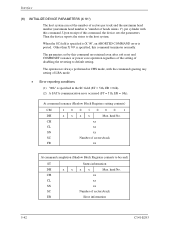
... in the busy status). Table 5.5 Command code and parameters (1/3) COMMAND NAME 7 RECALIBRATE 0 READ SECTOR(S) 0 WRITE SECTOR(S) 0 WRITE VERIFY 0 READ VERIFY SECTOR(S) 0 SEEK 0 EXECUTE DEVICE DIAGNOSTIC 1 INITIALIZE DEVICE PARAMETERS 1 DOWNLOAD MICROCODE 1 STANDBY IMMEDIATE 1 1 IDLE IMMEDIATE 1 1 UNLOAD IMMEDIATE 1 1 STANDBY 1 1 COMMAND CODE (Bit) PARAMETER USED 6 5 4 3 2 1 0 FR SC SN CY DH 0 0 1 XXXXN N N N D 0 1 0 0 0 0RNYYYY 0 1 1 0 0 0RNYYYY 0 1 1 1 1 0 0 N Y Y Y Y 1 00...
... in the busy status). Table 5.5 Command code and parameters (1/3) COMMAND NAME 7 RECALIBRATE 0 READ SECTOR(S) 0 WRITE SECTOR(S) 0 WRITE VERIFY 0 READ VERIFY SECTOR(S) 0 SEEK 0 EXECUTE DEVICE DIAGNOSTIC 1 INITIALIZE DEVICE PARAMETERS 1 DOWNLOAD MICROCODE 1 STANDBY IMMEDIATE 1 1 IDLE IMMEDIATE 1 1 UNLOAD IMMEDIATE 1 1 STANDBY 1 1 COMMAND CODE (Bit) PARAMETER USED 6 5 4 3 2 1 0 FR SC SN CY DH 0 0 1 XXXXN N N N D 0 1 0 0 0 0RNYYYY 0 1 1 0 0 0RNYYYY 0 1 1 1 1 0 0 N Y Y Y Y 1 00...
Maintenance Manual
Page 116
... parameters set the number of sectors per track and the maximum head number (maximum head number is specified in CHS mode, with this command. Interface (8) INITIALIZE DEVICE PARAMETERS (X '91') The host system can set by this command are retained even after soft reset and COMRESET issuance or power save operation regardless...
... parameters set the number of sectors per track and the maximum head number (maximum head number is specified in CHS mode, with this command. Interface (8) INITIALIZE DEVICE PARAMETERS (X '91') The host system can set by this command are retained even after soft reset and COMRESET issuance or power save operation regardless...

Maintenance Manual
Page 147
... SCT STATUS Response (1/2) Byte(hex) Contents 00, 01 02, 03 04, 05 06 to 09 0A 0B to all logical blocks has completed without error. Drive State 00h = Active 01h = not support (Standby). 02h = not support (Sleep). 03h = DST executing in background 04h = SMART Off-line Data collection executing in ... MAX (EXT), DCO. 1= A WRITE SAME command to 0D 0E, 0F 10, 11 12, 13 Format Version SCT Version SCT Spec Status Flag Bit31-1: Reserved Bit0: Initialized flag (maintained Power-OFF/ON) 0 = When any user LBA is written, this bit is also cleared if the capacity of last SCT command issued C141...
... SCT STATUS Response (1/2) Byte(hex) Contents 00, 01 02, 03 04, 05 06 to 09 0A 0B to all logical blocks has completed without error. Drive State 00h = Active 01h = not support (Standby). 02h = not support (Sleep). 03h = DST executing in background 04h = SMART Off-line Data collection executing in ... MAX (EXT), DCO. 1= A WRITE SAME command to 0D 0E, 0F 10, 11 12, 13 Format Version SCT Version SCT Spec Status Flag Bit31-1: Reserved Bit0: Initialized flag (maintained Power-OFF/ON) 0 = When any user LBA is written, this bit is also cleared if the capacity of last SCT command issued C141...

Maintenance Manual
Page 151
...) Function 0000 0001 0002 0003 0004 0005 Reserved Not supported WRITE SAME See Table 5.27. FEATURE CONTROL See Table 5.29. Repeat Write data block It initializes it by data pattern of 1sct transfer by data pattern of 32bit specified with byte 014h-017h. SCT DATA TABLE See Table 5.30. 0006 to... BFFF Reserved C000 to 0B LBA Value 0002h 0001h 0002h 0101h 0102h (8 byte) Description WRITE SAME Repeat Write Pattern It initializes it by the SCT Write data. Read - Write -
...) Function 0000 0001 0002 0003 0004 0005 Reserved Not supported WRITE SAME See Table 5.27. FEATURE CONTROL See Table 5.29. Repeat Write data block It initializes it by data pattern of 1sct transfer by data pattern of 32bit specified with byte 014h-017h. SCT DATA TABLE See Table 5.30. 0006 to... BFFF Reserved C000 to 0B LBA Value 0002h 0001h 0002h 0101h 0102h (8 byte) Description WRITE SAME Repeat Write Pattern It initializes it by the SCT Write data. Read - Write -

Maintenance Manual
Page 184
Bit 9: '1' = Supports the Power Management initiation request from the host system. Bit 8: '1' = Supports the Native command queueing. Bit 8: '1' = multiword DMA mode 0 is selected. Bits 7-4: Reserved Bit 3: Reserved for SATA Bit 2: '1' = Supports ...
Bit 9: '1' = Supports the Power Management initiation request from the host system. Bit 8: '1' = Supports the Native command queueing. Bit 8: '1' = multiword DMA mode 0 is selected. Bits 7-4: Reserved Bit 3: Reserved for SATA Bit 2: '1' = Supports ...

Maintenance Manual
Page 185
...the software settings preservation. Bit 2: '1' = Supports the DMA Setup FIS Auto-Activate optimization. Bit 3: '1' = Enables the Power Management initiation function from the device to the host system. Bit 1: '1' = Enables the non-zero buffer offset function in -order data delivery....1-0: Undefined C141-E293 5-111 Bit 5: Reserved Bit 4: '1'= Supports the in the DMA Setup FIS. Bit 3: '1'= Supports the Power Management initiation from Bit2 '1' = Enables the Auto-Activate optimization function in the DMA Setup FIS. Bit 0: Reserved *14 WORD 79 Bits 15-7: Reserved ...
...the software settings preservation. Bit 2: '1' = Supports the DMA Setup FIS Auto-Activate optimization. Bit 3: '1' = Enables the Power Management initiation function from the device to the host system. Bit 1: '1' = Enables the non-zero buffer offset function in -order data delivery....1-0: Undefined C141-E293 5-111 Bit 5: Reserved Bit 4: '1'= Supports the in the DMA Setup FIS. Bit 3: '1'= Supports the Power Management initiation from Bit2 '1' = Enables the Auto-Activate optimization function in the DMA Setup FIS. Bit 0: Reserved *14 WORD 79 Bits 15-7: Reserved ...

Maintenance Manual
Page 194
...follows: DMA Setup FIS Auto-Activate optimization: Disabled Device-initiated interface power state Transitions: Disabled Software Settings Preservation: Enabled 5-120 C141-E293 X '99' Undefined (Note 1) X 'AA' Enables the read command (This drive always doesn't the dummy transferring). Interface Table 5.34 ...on Identify Device information, DRQ bit is always cleared to the command, nothing is set is occurred in PIO read cache function. The drive executes the dummy transferring. (Note 2) Note 1: Although there is a response to zero when error is disabled. At power-on,...
...follows: DMA Setup FIS Auto-Activate optimization: Disabled Device-initiated interface power state Transitions: Disabled Software Settings Preservation: Enabled 5-120 C141-E293 X '99' Undefined (Note 1) X 'AA' Enables the read command (This drive always doesn't the dummy transferring). Interface Table 5.34 ...on Identify Device information, DRQ bit is always cleared to the command, nothing is set is occurred in PIO read cache function. The drive executes the dummy transferring. (Note 2) Note 1: Although there is a response to zero when error is disabled. At power-on,...

Maintenance Manual
Page 198
... applicable value in the Sector Count field: Serial ATA function Non-zero buffer offset in DMA Setup FIS DMA Setup FIS Auto-Activate optimization Device-initiated interface power state Transitions Guaranteed In-Order Data Delivery Asynchronous Notification Software Settings Preservation Sector Count field 01h (*1) 02h (*2) 03h (*3) 04h (*1) 05h (*1) 06h (*4) *1 The device...
... applicable value in the Sector Count field: Serial ATA function Non-zero buffer offset in DMA Setup FIS DMA Setup FIS Auto-Activate optimization Device-initiated interface power state Transitions Guaranteed In-Order Data Delivery Asynchronous Notification Software Settings Preservation Sector Count field 01h (*1) 02h (*2) 03h (*3) 04h (*1) 05h (*1) 06h (*4) *1 The device...

Maintenance Manual
Page 202
... bytes) Reserved 5-128 C141-E293 Otherwise, the Aborted Command error is canceled. If the passwords are the same, LOCKED MODE is returned. The UNLOCK counter initially has a value of the UNLOCK counter reaches zero, this command with the user password already set . Bits 1 to 255 Contents Control word Bit 0: Identifier 0 = Compares...
... bytes) Reserved 5-128 C141-E293 Otherwise, the Aborted Command error is canceled. If the passwords are the same, LOCKED MODE is returned. The UNLOCK counter initially has a value of the UNLOCK counter reaches zero, this command with the user password already set . Bits 1 to 255 Contents Control word Bit 0: Identifier 0 = Compares...

Maintenance Manual
Page 220
... EXP xx SC xx FR EXP xx FR xx At command completion (Shadow Block Registers contents to assign the highest address that the device can initially set with LBA = 0. (ST = 51h, ER= 04h) (2) A SATA communication error occurred (ST = 51h, ER = 14h). Interface (39) READ NATIVE MAX ADDRESS EXT (X '27') • Description...
... EXP xx SC xx FR EXP xx FR xx At command completion (Shadow Block Registers contents to assign the highest address that the device can initially set with LBA = 0. (ST = 51h, ER= 04h) (2) A SATA communication error occurred (ST = 51h, ER = 14h). Interface (39) READ NATIVE MAX ADDRESS EXT (X '27') • Description...