Hardware Guide
Page 2
... on this manual is required. This manual explains the procedures required to install your XG2600 and should be read and understood before you start using your XG2600. Copyright FUJITSU LIMITED 2011 2 XG2600 Hardware Guide Preface You have purchased the XG2600, a compact, 26 port 10 Gigabit Ethernet layer 2 switch that achieves unsurpassed standards of high throughput and low...
... on this manual is required. This manual explains the procedures required to install your XG2600 and should be read and understood before you start using your XG2600. Copyright FUJITSU LIMITED 2011 2 XG2600 Hardware Guide Preface You have purchased the XG2600, a compact, 26 port 10 Gigabit Ethernet layer 2 switch that achieves unsurpassed standards of high throughput and low...
Hardware Guide
Page 5
XG2600 Hardware Guide Contents Contents Preface ...2 LICENSE AGREEMENT ...3... Safety ...14 High safety ...14 Laser Safety ...15 Notes on Rack Mounting and Connecting a Powerstrip 15 About Fujitsu's Green Products ...15 Notes on Use ...16 Chapter 1 Getting Started 17 1.1 Items in the Package, Descriptions... Front Access or Rear Access (User Configured Airflow 19 1.1.3 Switch Fan Unit Side ...20 1.1.4 Switch Port Side ...22 1.1.5 Top Surface ...25 1.1.6 BOTTOM Surface ...26 1.2 Option ...27 1.2.1 SFP+ Modules ...27 Chapter 2 Installation 28 2.1 Requirements for Installation Environment 29...
XG2600 Hardware Guide Contents Contents Preface ...2 LICENSE AGREEMENT ...3... Safety ...14 High safety ...14 Laser Safety ...15 Notes on Rack Mounting and Connecting a Powerstrip 15 About Fujitsu's Green Products ...15 Notes on Use ...16 Chapter 1 Getting Started 17 1.1 Items in the Package, Descriptions... Front Access or Rear Access (User Configured Airflow 19 1.1.3 Switch Fan Unit Side ...20 1.1.4 Switch Port Side ...22 1.1.5 Top Surface ...25 1.1.6 BOTTOM Surface ...26 1.2 Option ...27 1.2.1 SFP+ Modules ...27 Chapter 2 Installation 28 2.1 Requirements for Installation Environment 29...

Hardware Guide
Page 17
Chapter 1 Getting Started This chapter lists the items that should be in the product package, and describes the names and functions of the various components. 1.1 Items in the Package, Descriptions and Functions 18 1.1.1 Parts List 18 1.1.2 Installation of Switch: Front Access or Rear Access (User Configured Airflow 19 1.1.3 Switch Fan Unit Side 20 1.1.4 Switch Port Side 22 1.1.5 Top Surface 25 1.1.6 BOTTOM Surface 26 1.2 Option 27 1.2.1 SFP+ Modules 27
Chapter 1 Getting Started This chapter lists the items that should be in the product package, and describes the names and functions of the various components. 1.1 Items in the Package, Descriptions and Functions 18 1.1.1 Parts List 18 1.1.2 Installation of Switch: Front Access or Rear Access (User Configured Airflow 19 1.1.3 Switch Fan Unit Side 20 1.1.4 Switch Port Side 22 1.1.5 Top Surface 25 1.1.6 BOTTOM Surface 26 1.2 Option 27 1.2.1 SFP+ Modules 27
Hardware Guide
Page 22
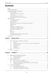
... Port 1 is the upper side of the leftmost port, and Port 26 is the lower side of the right most port. • Reset Switch Press to reboot. • USB Port Insert a USB memory device to load/save configuration files or update firmware. • Serial Port (Console Connection) The Serial Port...If you connect the device that have MDI fixed port to Serial Adapter) and RS232C crossover cable (D-SUB9). XG2600 Hardware Guide 1.1.4 Switch Port Side PSU Slots for Rear-Access Installation Port1 SFP+ Slots Chapter 1 Getting Started Serial Port Reset Switch Port25 PSU1 Power Supply Unit Power ...
... Port 1 is the upper side of the leftmost port, and Port 26 is the lower side of the right most port. • Reset Switch Press to reboot. • USB Port Insert a USB memory device to load/save configuration files or update firmware. • Serial Port (Console Connection) The Serial Port...If you connect the device that have MDI fixed port to Serial Adapter) and RS232C crossover cable (D-SUB9). XG2600 Hardware Guide 1.1.4 Switch Port Side PSU Slots for Rear-Access Installation Port1 SFP+ Slots Chapter 1 Getting Started Serial Port Reset Switch Port25 PSU1 Power Supply Unit Power ...
Hardware Guide
Page 48
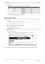
...Diameter 62.5/125µm 50/125µm Minimum Transimission Band Cable Length (m) 160MHz/km 26 200MHz/km 33 400MHz/km 66 500MHz/km 82 2000MHz/km 300 Use the appropriate cable... according to the selective status by "Setting of physical port" of Physical Port", and click "Regist" icon. 2. Make the replacing SFP+ slot to the "disable ...+ module. 48 Connecting the Equipment Select "Disuse" of "Use of settings menu. XG2600 Hardware Guide Chapter 2 Installation Precautions Cable length will be as below . 1. When replacing SFP+ module, ...
...Diameter 62.5/125µm 50/125µm Minimum Transimission Band Cable Length (m) 160MHz/km 26 200MHz/km 33 400MHz/km 66 500MHz/km 82 2000MHz/km 300 Use the appropriate cable... according to the selective status by "Setting of physical port" of Physical Port", and click "Regist" icon. 2. Make the replacing SFP+ slot to the "disable ...+ module. 48 Connecting the Equipment Select "Disuse" of "Use of settings menu. XG2600 Hardware Guide Chapter 2 Installation Precautions Cable length will be as below . 1. When replacing SFP+ module, ...
Hardware Guide
Page 57
XG2600 Hardware Guide Index B BOTTOM Surface 26 C CD-ROM 19 CHECK LED 20, 23 Communication Software 51 Connecting the Equipment 44 Console cable adapter 18 Console port 51 E ERROR LED 23 F FAN LED 23 Fan Unit 20 FDX LED 23 FLASH LED 23 Front-Access Configuration 33 H Hardware 51 I Install the...Rails 18 Rating Label 25 READY LED 20, 23 Rear-Access Configuration 31 Requirements for Installation Environment 29 Reset Switch 22 RS232C cable 51 S Serial Port (Console Connection 22 SFP+ Dummy Caps 18 SFP+ LED 23 SFP+ LINK/ACT LED 23 SFP+ Module 27 SFP+ Slots 22 Software 51 ...
XG2600 Hardware Guide Index B BOTTOM Surface 26 C CD-ROM 19 CHECK LED 20, 23 Communication Software 51 Connecting the Equipment 44 Console cable adapter 18 Console port 51 E ERROR LED 23 F FAN LED 23 Fan Unit 20 FDX LED 23 FLASH LED 23 Front-Access Configuration 33 H Hardware 51 I Install the...Rails 18 Rating Label 25 READY LED 20, 23 Rear-Access Configuration 31 Requirements for Installation Environment 29 Reset Switch 22 RS232C cable 51 S Serial Port (Console Connection 22 SFP+ Dummy Caps 18 SFP+ LED 23 SFP+ LINK/ACT LED 23 SFP+ Module 27 SFP+ Slots 22 Software 51 ...