Hardware Guide
Page 3
... it is copyrighted by Fujitsu Limited ("Fujitsu"). Scope of Warranty 1) If Customer notifies Fujitsu of any discrepancy between the manual, user guides or other related documents ("Documentation") and the Software, Fujitsu shall, at its sole discretion: a. b. or 3 The use of the Product is limited to the number of licenses 1 Thank you for damages and expenses attributable to use , installation or backup of the Product constitutes...
... it is copyrighted by Fujitsu Limited ("Fujitsu"). Scope of Warranty 1) If Customer notifies Fujitsu of any discrepancy between the manual, user guides or other related documents ("Documentation") and the Software, Fujitsu shall, at its sole discretion: a. b. or 3 The use of the Product is limited to the number of licenses 1 Thank you for damages and expenses attributable to use , installation or backup of the Product constitutes...
Hardware Guide
Page 5
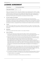
... Notes on Rack Mounting and Connecting a Powerstrip 15 About Fujitsu's Green Products ...15 Notes on Use ...16 Chapter 1 Getting Started 17 1.1 Items in the Package, Descriptions and Functions 18 1.1.1 Parts List ...18 1.1.2 Installation of Switch: Front Access or Rear Access (User Configured Airflow 19 1.1.3 Switch Fan Unit Side ...20 1.1.4 Switch Port Side ...22 1.1.5 Top Surface ...25 1.1.6 BOTTOM Surface ...26 1.2 Option ...27 1.2.1 SFP+ Modules ...27 Chapter 2 Installation 28 2.1 Requirements for Installation Environment 29 2.1.1 Installation Requirements ...29...
... Notes on Rack Mounting and Connecting a Powerstrip 15 About Fujitsu's Green Products ...15 Notes on Use ...16 Chapter 1 Getting Started 17 1.1 Items in the Package, Descriptions and Functions 18 1.1.1 Parts List ...18 1.1.2 Installation of Switch: Front Access or Rear Access (User Configured Airflow 19 1.1.3 Switch Fan Unit Side ...20 1.1.4 Switch Port Side ...22 1.1.5 Top Surface ...25 1.1.6 BOTTOM Surface ...26 1.2 Option ...27 1.2.1 SFP+ Modules ...27 Chapter 2 Installation 28 2.1 Requirements for Installation Environment 29 2.1.1 Installation Requirements ...29...

Hardware Guide
Page 12
..., and dust. Do not install this device near heaters or at the light source (e.g. Do not install this device on . Avoid looking at places subject to follow this device for access to, and cabling of power supply units or fan units in order to use the device in a corrosive gas environments or other connected equipment. Failure to person or failure. Installing outdoors may cause damage...
..., and dust. Do not install this device near heaters or at the light source (e.g. Do not install this device on . Avoid looking at places subject to follow this device for access to, and cabling of power supply units or fan units in order to use the device in a corrosive gas environments or other connected equipment. Failure to person or failure. Installing outdoors may cause damage...
Hardware Guide
Page 13
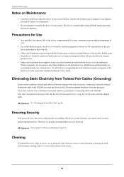
... authorized firmware upgrades, for any errors or data loss arising from Twisted Pair Cables (Grounding) Under certain conditions, twisted pair cables can become charged with a Fujitsu service engineer or an engineer certified by Fujitsu for maintenance. • Do not dismantle or modify this hardware guide, the device, its LAN port to operate falsely or to the XG2600 can cause the device or its firmware, and the management software...
... authorized firmware upgrades, for any errors or data loss arising from Twisted Pair Cables (Grounding) Under certain conditions, twisted pair cables can become charged with a Fujitsu service engineer or an engineer certified by Fujitsu for maintenance. • Do not dismantle or modify this hardware guide, the device, its LAN port to operate falsely or to the XG2600 can cause the device or its firmware, and the management software...

Hardware Guide
Page 15
... Optical Transceiver Approved Vendor List (obtainable from the optical module's port openings. Assure a good ground connection exists before connecting power to the following Fujitsu Web site. The maximum current leakage for use in the XG2600 must only be mounted in property damage, electric shock, or fire. • Monitor and control the internal and external temperature and humidity of the rack, so that conform to...
... Optical Transceiver Approved Vendor List (obtainable from the optical module's port openings. Assure a good ground connection exists before connecting power to the following Fujitsu Web site. The maximum current leakage for use in the XG2600 must only be mounted in property damage, electric shock, or fire. • Monitor and control the internal and external temperature and humidity of the rack, so that conform to...
Hardware Guide
Page 16
... power off or reset the system during a firmware update, or the device cannot be enabled. • A User's Guide for this device, please read the following. • Customers are still not available after the configuration is available, it may cause difficulties and delays for the support engineer to restore the device, Please backup the configuration information on a timely manner and always maintain it up to restore configurations in PDF format. XG2600 Hardware Guide...
... power off or reset the system during a firmware update, or the device cannot be enabled. • A User's Guide for this device, please read the following. • Customers are still not available after the configuration is available, it may cause difficulties and delays for the support engineer to restore the device, Please backup the configuration information on a timely manner and always maintain it up to restore configurations in PDF format. XG2600 Hardware Guide...
Hardware Guide
Page 19
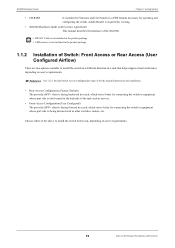
... available to install the switch in a different direction in a rack that helps suppress heat interference, depending on user's requirements Reference See "2.2.1 Decide Switch Access Configuration" (pg.31) for the detailed instructions for installation. • Rear-Access Configuration (Factory Default) The port side (SFP+ slots) is facing backward in a rack, which serves better for connecting the switch to equipment whose port side is facing forward such as servers. • Front-Access Configuration (User Configured) The port side (SFP+ slots...
... available to install the switch in a different direction in a rack that helps suppress heat interference, depending on user's requirements Reference See "2.2.1 Decide Switch Access Configuration" (pg.31) for the detailed instructions for installation. • Rear-Access Configuration (Factory Default) The port side (SFP+ slots) is facing backward in a rack, which serves better for connecting the switch to equipment whose port side is facing forward such as servers. • Front-Access Configuration (User Configured) The port side (SFP+ slots...
Hardware Guide
Page 20
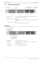
... Front-Access Configuration Power Supply Units are plugged in the slots when the switch is used in orange when there is a problem. Lights to show the direction of fan (airflow). 20 Items in the Package, Descriptions and Functions XG2600 Hardware Guide 1.1.3 Switch Fan Unit Side MAC Firmware Label Fan Unit Chapter 1 Getting Started PSU Slots for model name, Front-Access Configuration serial number label XG2600 FAN2 FAN1 PSU2 PSU1 • MAC Firmware Label This indicates the MAC addresses and firmware...
... Front-Access Configuration Power Supply Units are plugged in the slots when the switch is used in orange when there is a problem. Lights to show the direction of fan (airflow). 20 Items in the Package, Descriptions and Functions XG2600 Hardware Guide 1.1.3 Switch Fan Unit Side MAC Firmware Label Fan Unit Chapter 1 Getting Started PSU Slots for model name, Front-Access Configuration serial number label XG2600 FAN2 FAN1 PSU2 PSU1 • MAC Firmware Label This indicates the MAC addresses and firmware...
Hardware Guide
Page 22
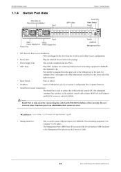
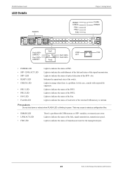
... fixed port to the Management Port, please use the Crossover Cable. 22 Items in the package. • Power Supply Unit This switch is only used for connecting the switch with the console (PC) for connecting Ethernet based networking equipment (10GBASESR/10GBASE-LR). Caution Serial Port is installed with two PSUs. • SFP+ Slots Plug SFP+ modules for setting and command line interface via the attached console cable adapter (RJ45 to load/save configuration files or update firmware. • Serial Port (Console Connection) The Serial Port is MDI fixed. For example, Port...
... fixed port to the Management Port, please use the Crossover Cable. 22 Items in the package. • Power Supply Unit This switch is only used for connecting the switch with the console (PC) for connecting Ethernet based networking equipment (10GBASESR/10GBASE-LR). Caution Serial Port is installed with two PSUs. • SFP+ Slots Plug SFP+ modules for setting and command line interface via the attached console cable adapter (RJ45 to load/save configuration files or update firmware. • Serial Port (Console Connection) The Serial Port is MDI fixed. For example, Port...
Hardware Guide
Page 23
... to destroy configuration files. • ERROR LED • LINK/ACT LED • FDX LED There's a problem with responsible engineers. In this case, consult with USB memory or SFP+ modules, or mount/access error. Lights to indicate the status of the SFP+ slot. Lights to indicate the status of the switch. Precautions Do not shut down or reboot when FLASH LED is a problem. Indicates the operational state of the Fan. Lights to indicate the status of read...
... to destroy configuration files. • ERROR LED • LINK/ACT LED • FDX LED There's a problem with responsible engineers. In this case, consult with USB memory or SFP+ modules, or mount/access error. Lights to indicate the status of the SFP+ slot. Lights to indicate the status of the switch. Precautions Do not shut down or reboot when FLASH LED is a problem. Indicates the operational state of the Fan. Lights to indicate the status of read...
Hardware Guide
Page 24
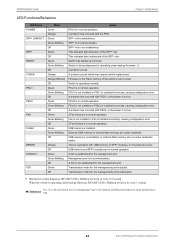
... and Functions Management port is in normal operation. PSU1 is not installed or PSU1 is installed. Fan is not installed or Fan is installed incorrectly, causing configuration error. 2 Fan Units are in every 1 second. When the switch is operating under backup firmware. (*) A problem occurs. USB memory and SFP+ modules are in communication. XG2600 Hardware Guide Chapter 1 Getting Started LED Functions/Behaviors LED Name POWER SFP+ LINK/ACT SFP+ READY CHECK PSU1 PSU2 FAN FLASH ERROR LINK/ACT FDX State Green Orange Green Green Blinking Off Green Off Green Green Blinking Off...
... and Functions Management port is in normal operation. PSU1 is not installed or PSU1 is installed. Fan is not installed or Fan is installed incorrectly, causing configuration error. 2 Fan Units are in every 1 second. When the switch is operating under backup firmware. (*) A problem occurs. USB memory and SFP+ modules are in communication. XG2600 Hardware Guide Chapter 1 Getting Started LED Functions/Behaviors LED Name POWER SFP+ LINK/ACT SFP+ READY CHECK PSU1 PSU2 FAN FLASH ERROR LINK/ACT FDX State Green Orange Green Green Blinking Off Green Off Green Green Blinking Off...
Hardware Guide
Page 28
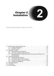
... 2.1.1 Installation Requirements 29 2.1.2 Space Requirements 30 2.2 Installation of the switch 31 2.2.1 Decide Switch Access Configuration 31 2.2.2 Rear-Access Configuration (Factory Default 35 2.2.3 Change Switch Access Configurations from Rear-Access (Factory Default) to FrontAccess and Install 38 2.3 Connecting the Equipment 44 2.3.1 Discharging Twisted Pair Cable 44 2.3.2 Cleaning SFP+ Module / Optical Connector 44 2.3.3 Connecting Twisted Pair Cable / SFP+ Module 46 2.3.4 Plugging in the USB Memory 50 2.4 Connecting a Setup PC 51 2.5 Time Setting 55 2.6 Set up IP address 56
... 2.1.1 Installation Requirements 29 2.1.2 Space Requirements 30 2.2 Installation of the switch 31 2.2.1 Decide Switch Access Configuration 31 2.2.2 Rear-Access Configuration (Factory Default 35 2.2.3 Change Switch Access Configurations from Rear-Access (Factory Default) to FrontAccess and Install 38 2.3 Connecting the Equipment 44 2.3.1 Discharging Twisted Pair Cable 44 2.3.2 Cleaning SFP+ Module / Optical Connector 44 2.3.3 Connecting Twisted Pair Cable / SFP+ Module 46 2.3.4 Plugging in the USB Memory 50 2.4 Connecting a Setup PC 51 2.5 Time Setting 55 2.6 Set up IP address 56
Hardware Guide
Page 49
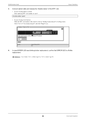
... case ERROR LED was blinking before replacement, confirm that ERROR LED is off after replacement. XG2600 Hardware Guide Chapter 2 Installation 3. Select "Use" of "Use of settings menu. Reference User's Guide "5.43.1.1 offline" (pg.532), "5.43.1.2 online" (pg.533) 49 Connecting the Equipment Connect optical cable and release the "disable status" of the SFP+ slot. • In case of using telnet or console Enter replacing SFP+ slot number in # online ether • In case of using www browser Make the SFP+ slot number...
... case ERROR LED was blinking before replacement, confirm that ERROR LED is off after replacement. XG2600 Hardware Guide Chapter 2 Installation 3. Select "Use" of "Use of settings menu. Reference User's Guide "5.43.1.1 offline" (pg.532), "5.43.1.2 online" (pg.533) 49 Connecting the Equipment Connect optical cable and release the "disable status" of the SFP+ slot. • In case of using telnet or console Enter replacing SFP+ slot number in # online ether • In case of using www browser Make the SFP+ slot number...
Hardware Guide
Page 50
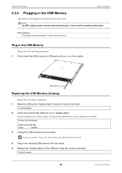
... the switch. Make the USB port to "disable status" using the console command. # usbctl enable 50 Connecting the Equipment Release the "disable status" of the switch. Execute command "show usb hcd status [USB HCD STATUS] status : disable 3. XG2600 Hardware Guide Chapter 2 Installation 2.3.4 Plugging in the USB Memory USB memory can be plugged in the USB Memory Please refer to the following instructions; 1. USB Memory Replacing the USB Memory (Unplug) Please refer to USB port on . Check and...
... the switch. Make the USB port to "disable status" using the console command. # usbctl enable 50 Connecting the Equipment Release the "disable status" of the switch. Execute command "show usb hcd status [USB HCD STATUS] status : disable 3. XG2600 Hardware Guide Chapter 2 Installation 2.3.4 Plugging in the USB Memory USB memory can be plugged in the USB Memory Please refer to the following instructions; 1. USB Memory Replacing the USB Memory (Unplug) Please refer to USB port on . Check and...
Hardware Guide
Page 52
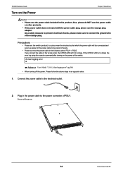
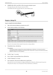
... turning off easily. • Please connect the power cable in the following order. Precautions • Please set the switch (product) to a place near the electrical outlet which the power cable will lit in an opposite order. 1. Plug in this power cable on the Power Chapter 2 Installation Caution • Please use the change plug. If the CHECK LED is lit, delete the error log using the console command after turning on . 52 Connecting a Setup PC XG2600 Hardware Guide Turn...
... turning off easily. • Please connect the power cable in the following order. Precautions • Please set the switch (product) to a place near the electrical outlet which the power cable will lit in an opposite order. 1. Plug in this power cable on the Power Chapter 2 Installation Caution • Please use the change plug. If the CHECK LED is lit, delete the error log using the console command after turning on . 52 Connecting a Setup PC XG2600 Hardware Guide Turn...
Hardware Guide
Page 53
... 2 Installation Prepare a Setup PC Log on screen. 5. Please wait for such process to the power connecter of the other operation... 4. In such case, the switch is processing another job, and waiting for a moment until it through terminal command) Number of the switch will light in green. Confirm "Login :" on using the set at the initial state, simply press [Return] key or [Enter] key without keying in the password...
... 2 Installation Prepare a Setup PC Log on screen. 5. Please wait for such process to the power connecter of the other operation... 4. In such case, the switch is processing another job, and waiting for a moment until it through terminal command) Number of the switch will light in green. Confirm "Login :" on using the set at the initial state, simply press [Return] key or [Enter] key without keying in the password...
Hardware Guide
Page 56
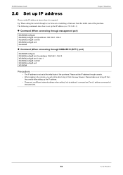
... 192.168.1.1) z Command (When connecting through www browser or installing a firmware from the www browser. When setting the switch through management port) XG2600# configure XG2600(config)# oob ip address 192.168.1.1/24 3 XG2600(config)# commit XG2600(config)# exit XG2600# z Command (When connecting through10GBASE-R (SFP+) port) XG2600# configure XG2600(config)# lan 0 ip address 192.168.1.1/24 3 XG2600(config)# lan 0 vlan 1 XG2600(config)# commit XG2600(config)# exit XG2600# Precautions • The IP address is required. Please set the IP address through console. • When logging in...
... 192.168.1.1) z Command (When connecting through www browser or installing a firmware from the www browser. When setting the switch through management port) XG2600# configure XG2600(config)# oob ip address 192.168.1.1/24 3 XG2600(config)# commit XG2600(config)# exit XG2600# z Command (When connecting through10GBASE-R (SFP+) port) XG2600# configure XG2600(config)# lan 0 ip address 192.168.1.1/24 3 XG2600(config)# lan 0 vlan 1 XG2600(config)# commit XG2600(config)# exit XG2600# Precautions • The IP address is required. Please set the IP address through console. • When logging in...
Hardware Guide
Page 57
... LED 23 R Rack mounting 43 Rack Mounting Rails 18 Rating Label 25 READY LED 20, 23 Rear-Access Configuration 31 Requirements for Installation Environment 29 Reset Switch 22 RS232C cable 51 S Serial Port (Console Connection 22 SFP+ Dummy Caps 18 SFP+ LED 23 SFP+ LINK/ACT LED 23 SFP+ Module 27 SFP+ Slots 22 Software 51 Space Requirements 30 STATUS LED 20 Switch Fan Unit Side 20 Switch Port Side 22 T Temperature and Humidity Requirements 29 terminal software 53 Top Surface 25 Turn on the Power...
... LED 23 R Rack mounting 43 Rack Mounting Rails 18 Rating Label 25 READY LED 20, 23 Rear-Access Configuration 31 Requirements for Installation Environment 29 Reset Switch 22 RS232C cable 51 S Serial Port (Console Connection 22 SFP+ Dummy Caps 18 SFP+ LED 23 SFP+ LINK/ACT LED 23 SFP+ Module 27 SFP+ Slots 22 Software 51 Space Requirements 30 STATUS LED 20 Switch Fan Unit Side 20 Switch Port Side 22 T Temperature and Humidity Requirements 29 terminal software 53 Top Surface 25 Turn on the Power...
Quick Start Guide
Page 1
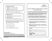
... -RJ45 cable adapter included with , install, configure and deploy the switch. When the switch Ready LED stops blinking, login via the terminal session: Login: admin Password: [ENTER] weak admin's password: set the password XG2600# _ to assure successful deployment in the Support and Downloads section of time: 1. Fujitsu and the Fujitsu logo are registered trademarks. This Quick Start Guide is recommended that all items are available in a minimum amount of Fujitsu website: http://us.fujitsu.com/ethernet For technical support...
... -RJ45 cable adapter included with , install, configure and deploy the switch. When the switch Ready LED stops blinking, login via the terminal session: Login: admin Password: [ENTER] weak admin's password: set the password XG2600# _ to assure successful deployment in the Support and Downloads section of time: 1. Fujitsu and the Fujitsu logo are registered trademarks. This Quick Start Guide is recommended that all items are available in a minimum amount of Fujitsu website: http://us.fujitsu.com/ethernet For technical support...
Quick Start Guide
Page 2
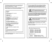
... management port oob ip address 3 # Set date, time, and time zone offset from Fujitsu to expand networking attachments to take affect. # This command prompts for in section 1.1.2 Installation of Switch: Front Access or Rear Access (User Configured Airflow ) and complete reconfiguration of the XG User's Guide (CD-ROM). # After login: configure # This command prompts for a password password admin set # Switch name sysname # Set up the switch for a y/n reply. Stepping through the preceding instructions completes installation of the Hardware Guide before rack mounting the switch...
... management port oob ip address 3 # Set date, time, and time zone offset from Fujitsu to expand networking attachments to take affect. # This command prompts for in section 1.1.2 Installation of Switch: Front Access or Rear Access (User Configured Airflow ) and complete reconfiguration of the XG User's Guide (CD-ROM). # After login: configure # This command prompts for a password password admin set # Switch name sysname # Set up the switch for a y/n reply. Stepping through the preceding instructions completes installation of the Hardware Guide before rack mounting the switch...

