Hardware Guide
Page 5
XG2600 Hardware Guide Contents Contents Preface ...2 LICENSE AGREEMENT ...3 Organization ...14 Safety ...14 High safety ...14 Laser Safety ...15 Notes on Rack Mounting and Connecting a Powerstrip 15 About Fujitsu's Green Products ...15 Notes on Use ...16 Chapter 1 Getting Started 17 1.1 Items in the Package, Descriptions and... Functions 18 1.1.1 Parts List ...18 1.1.2 Installation of Switch: Front Access or Rear Access (User Configured Airflow 19 1.1.3 Switch Fan Unit Side ...20 1.1.4 Switch Port Side ...22 1.1.5 Top Surface ...25 1.1.6 BOTTOM Surface ...26 ...
XG2600 Hardware Guide Contents Contents Preface ...2 LICENSE AGREEMENT ...3 Organization ...14 Safety ...14 High safety ...14 Laser Safety ...15 Notes on Rack Mounting and Connecting a Powerstrip 15 About Fujitsu's Green Products ...15 Notes on Use ...16 Chapter 1 Getting Started 17 1.1 Items in the Package, Descriptions and... Functions 18 1.1.1 Parts List ...18 1.1.2 Installation of Switch: Front Access or Rear Access (User Configured Airflow 19 1.1.3 Switch Fan Unit Side ...20 1.1.4 Switch Port Side ...22 1.1.5 Top Surface ...25 1.1.6 BOTTOM Surface ...26 ...
Hardware Guide
Page 13
...use water or a mild detergent to become statically charged again. XG2600 Hardware Guide Notes on the network can become charged with a Fujitsu service engineer or an engineer certified by Fujitsu for maintenance. • Do not dismantle or modify this ... are the responsibility of any authorized firmware upgrades, for any more than the original purchase price. • Fujitsu and its partners do not approve of any use . Use a static removal tool to discharge twisted pair cables...Twisted Pair Cables (Grounding) Under certain conditions, twisted pair cables can configure this device.
...use water or a mild detergent to become statically charged again. XG2600 Hardware Guide Notes on the network can become charged with a Fujitsu service engineer or an engineer certified by Fujitsu for maintenance. • Do not dismantle or modify this ... are the responsibility of any authorized firmware upgrades, for any more than the original purchase price. • Fujitsu and its partners do not approve of any use . Use a static removal tool to discharge twisted pair cables...Twisted Pair Cables (Grounding) Under certain conditions, twisted pair cables can configure this device.
Hardware Guide
Page 16
... following. • Customers are still not available after the configuration is complete. Therefore, some of failure. The configuration information can be restored to its normal condition by Fujitsu or Fujitsu's certified support engineer to lightning or electrostatic discharge beyond the threshold of the protection circuit. XG2600 Hardware Guide Notes on Use Before using this product...
... following. • Customers are still not available after the configuration is complete. Therefore, some of failure. The configuration information can be restored to its normal condition by Fujitsu or Fujitsu's certified support engineer to lightning or electrostatic discharge beyond the threshold of the protection circuit. XG2600 Hardware Guide Notes on Use Before using this product...
Hardware Guide
Page 17
Chapter 1 Getting Started This chapter lists the items that should be in the product package, and describes the names and functions of the various components. 1.1 Items in the Package, Descriptions and Functions 18 1.1.1 Parts List 18 1.1.2 Installation of Switch: Front Access or Rear Access (User Configured Airflow 19 1.1.3 Switch Fan Unit Side 20 1.1.4 Switch Port Side 22 1.1.5 Top Surface 25 1.1.6 BOTTOM Surface 26 1.2 Option 27 1.2.1 SFP+ Modules 27
Chapter 1 Getting Started This chapter lists the items that should be in the product package, and describes the names and functions of the various components. 1.1 Items in the Package, Descriptions and Functions 18 1.1.1 Parts List 18 1.1.2 Installation of Switch: Front Access or Rear Access (User Configured Airflow 19 1.1.3 Switch Fan Unit Side 20 1.1.4 Switch Port Side 22 1.1.5 Top Surface 25 1.1.6 BOTTOM Surface 26 1.2 Option 27 1.2.1 SFP+ Modules 27
Hardware Guide
Page 19
... servers. • Front-Access Configuration (User Configured) The port side (SFP+ slots) is facing forward such as other switches, routers, etc. Adobe Reader is required for viewing. • XG2600 Hardware Guide (with Licence Agreement) This manual describes the hardware of the XG2600. • RS232C Cable is ... the switch in the rack, depending on user's requirements. 19 Items in a PDF format) necessary for operating and configuring the switch. XG2600 Hardware Guide Chapter 1 Getting Started • CD-ROM It contains the Firmware and User Guide (in the Package, Descriptions and Functions...
... servers. • Front-Access Configuration (User Configured) The port side (SFP+ slots) is facing forward such as other switches, routers, etc. Adobe Reader is required for viewing. • XG2600 Hardware Guide (with Licence Agreement) This manual describes the hardware of the XG2600. • RS232C Cable is ... the switch in the rack, depending on user's requirements. 19 Items in a PDF format) necessary for operating and configuring the switch. XG2600 Hardware Guide Chapter 1 Getting Started • CD-ROM It contains the Firmware and User Guide (in the Package, Descriptions and Functions...
Hardware Guide
Page 20
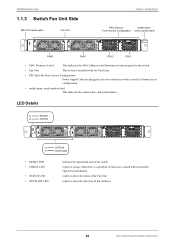
...is a problem. In that case, consult with two Fan Units. • PSU Slots for model name, Front-Access Configuration serial number label XG2600 FAN2 FAN1 PSU2 PSU1 • MAC Firmware Label This indicates the MAC addresses and firmware revision assigned to the switch. ... responsible engineers immediately. Lights to show the status of the switch. XG2600 Hardware Guide 1.1.3 Switch Fan Unit Side MAC Firmware Label Fan Unit Chapter 1 Getting Started PSU Slots for Front-Access Configuration Power Supply Units are plugged in the Package, Descriptions and Functions
...is a problem. In that case, consult with two Fan Units. • PSU Slots for model name, Front-Access Configuration serial number label XG2600 FAN2 FAN1 PSU2 PSU1 • MAC Firmware Label This indicates the MAC addresses and firmware revision assigned to the switch. ... responsible engineers immediately. Lights to show the status of the switch. XG2600 Hardware Guide 1.1.3 Switch Fan Unit Side MAC Firmware Label Fan Unit Chapter 1 Getting Started PSU Slots for Front-Access Configuration Power Supply Units are plugged in the Package, Descriptions and Functions
Hardware Guide
Page 21
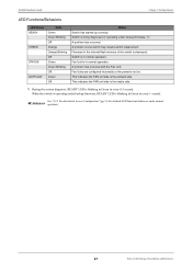
... backup firmware, READY LED is destroyed. Firmware in the internal flash memory of the switch is blinking in Green in normal operation. XG2600 Hardware Guide Chapter 1 Getting Started LED Functions/Behaviors LED Name READY CHECK STATUS OUTFLOW State Green Green Blinking Off Orange Orange Blinking Off.... Fan Unit is being diagnosed or operating under normal Reference operation. 21 Items in normal operation. See "2.2.1 Decide Switch Access Configuration" (pg.31) for detailed LED functions/behaviors under backup firmware. (*) A problem has occurred. Switch is not on. Fan Units are...
... backup firmware, READY LED is destroyed. Firmware in the internal flash memory of the switch is blinking in Green in normal operation. XG2600 Hardware Guide Chapter 1 Getting Started LED Functions/Behaviors LED Name READY CHECK STATUS OUTFLOW State Green Green Blinking Off Orange Orange Blinking Off.... Fan Unit is being diagnosed or operating under normal Reference operation. 21 Items in normal operation. See "2.2.1 Decide Switch Access Configuration" (pg.31) for detailed LED functions/behaviors under backup firmware. (*) A problem has occurred. Switch is not on. Fan Units are...
Hardware Guide
Page 22
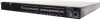
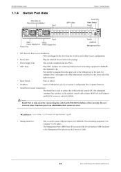
...side of the right most port. • Reset Switch Press to reboot. • USB Port Insert a USB memory device to load/save configuration files or update firmware. • Serial Port (Console Connection) The Serial Port is used for connecting the switch with two PSUs. •... User's Guide "1.1.5 Console Port Specifications" (pg.29) • Management Port This is used to the right. Use Category-5 LAN cables. XG2600 Hardware Guide 1.1.4 Switch Port Side PSU Slots for Rear-Access Installation Port1 SFP+ Slots Chapter 1 Getting Started Serial Port Reset Switch Port25 PSU1 ...
...side of the right most port. • Reset Switch Press to reboot. • USB Port Insert a USB memory device to load/save configuration files or update firmware. • Serial Port (Console Connection) The Serial Port is used for connecting the switch with two PSUs. •... User's Guide "1.1.5 Console Port Specifications" (pg.29) • Management Port This is used to the right. Use Category-5 LAN cables. XG2600 Hardware Guide 1.1.4 Switch Port Side PSU Slots for Rear-Access Installation Port1 SFP+ Slots Chapter 1 Getting Started Serial Port Reset Switch Port25 PSU1 ...
Hardware Guide
Page 23
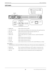
... memory or SFP+ modules, or mount/access error. Lights to indicate the status of read/write of the SFP+ slot. That may cause to destroy configuration files. • ERROR LED • LINK/ACT LED • FDX LED There's a problem with responsible engineers. Lights to indicate the status of ...Lights to indicate the status of the switch. Lights to indicate the status of the signal transmission. Lights to indicate the status of PSU. XG2600 Hardware Guide LED Details POWER READY CHECK PSU1 PSU2 FAN Chapter 1 Getting Started FLASH ERROR Port2 SFP+ LINK/ACT Port1 SFP+ LINK/ACT ...
... memory or SFP+ modules, or mount/access error. Lights to indicate the status of read/write of the SFP+ slot. That may cause to destroy configuration files. • ERROR LED • LINK/ACT LED • FDX LED There's a problem with responsible engineers. Lights to indicate the status of ...Lights to indicate the status of the switch. Lights to indicate the status of the signal transmission. Lights to indicate the status of PSU. XG2600 Hardware Guide LED Details POWER READY CHECK PSU1 PSU2 FAN Chapter 1 Getting Started FLASH ERROR Port2 SFP+ LINK/ACT Port1 SFP+ LINK/ACT ...
Hardware Guide
Page 24
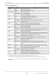
...of the SFP+ slot. Transmission mode for the management port is being diagnosed or operating under backup firmware. (*) A problem occurs. XG2600 Hardware Guide Chapter 1 Getting Started LED Functions/Behaviors LED Name POWER SFP+ LINK/ACT SFP+ READY CHECK PSU1 PSU2 FAN FLASH ... Functions A link is not established. PSU1 is not installed or PSU1 is installed incorrectly, causing configuration error. PSU2 is not installed or PSU2 is installed incorrectly, causing configuration error. External USB memory or internal flash memory are in normal operation. USB memory and SFP+...
...of the SFP+ slot. Transmission mode for the management port is being diagnosed or operating under backup firmware. (*) A problem occurs. XG2600 Hardware Guide Chapter 1 Getting Started LED Functions/Behaviors LED Name POWER SFP+ LINK/ACT SFP+ READY CHECK PSU1 PSU2 FAN FLASH ... Functions A link is not established. PSU1 is not installed or PSU1 is installed incorrectly, causing configuration error. PSU2 is not installed or PSU2 is installed incorrectly, causing configuration error. External USB memory or internal flash memory are in normal operation. USB memory and SFP+...
Hardware Guide
Page 28
... PC. 2.1 Requirements for Installation Environment 29 2.1.1 Installation Requirements 29 2.1.2 Space Requirements 30 2.2 Installation of the switch 31 2.2.1 Decide Switch Access Configuration 31 2.2.2 Rear-Access Configuration (Factory Default 35 2.2.3 Change Switch Access Configurations from Rear-Access (Factory Default) to FrontAccess and Install 38 2.3 Connecting the Equipment 44 2.3.1 Discharging Twisted Pair Cable 44 2.3.2 Cleaning SFP...
... PC. 2.1 Requirements for Installation Environment 29 2.1.1 Installation Requirements 29 2.1.2 Space Requirements 30 2.2 Installation of the switch 31 2.2.1 Decide Switch Access Configuration 31 2.2.2 Rear-Access Configuration (Factory Default 35 2.2.3 Change Switch Access Configurations from Rear-Access (Factory Default) to FrontAccess and Install 38 2.3 Connecting the Equipment 44 2.3.1 Discharging Twisted Pair Cable 44 2.3.2 Cleaning SFP...
Hardware Guide
Page 31
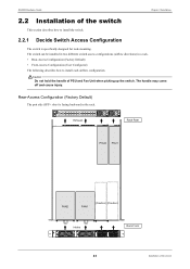
... in two different switch access configurations (airflow directions) in the rack. XG2600 Hardware Guide Chapter 2 Installation 2.2 Installation of the switch This section describes how to install the switch. 2.2.1 Decide Switch Access Configuration The switch is facing backward in a rack. • Rear-Access Configuration (Factory Default) • Front-Access Configuration (User Configured) The following describes how to...
... in two different switch access configurations (airflow directions) in the rack. XG2600 Hardware Guide Chapter 2 Installation 2.2 Installation of the switch This section describes how to install the switch. 2.2.1 Decide Switch Access Configuration The switch is facing backward in a rack. • Rear-Access Configuration (Factory Default) • Front-Access Configuration (User Configured) The following describes how to...
Hardware Guide
Page 32
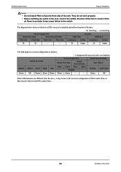
XG2600 Hardware Guide Chapter 2 Installation Caution • Do not install PSUs to face the front side of the switch PSU2 Slot - Green Off If the LED indicators are different from the above, it may cause failure to the switch The diagram below shows in which slots PSUs need to the incorrect configuration... and/or Fans. 32 Installation of the rack. They do not work properly. • Before installing the switch in a correct configuration as follows: - : Unsupported because the unit is correct. Installation Airflow Intake Installation Airflow Intake The LED lights...
XG2600 Hardware Guide Chapter 2 Installation Caution • Do not install PSUs to face the front side of the switch PSU2 Slot - Green Off If the LED indicators are different from the above, it may cause failure to the switch The diagram below shows in which slots PSUs need to the incorrect configuration... and/or Fans. 32 Installation of the rack. They do not work properly. • Before installing the switch in a correct configuration as follows: - : Unsupported because the unit is correct. Installation Airflow Intake Installation Airflow Intake The LED lights...
Hardware Guide
Page 33
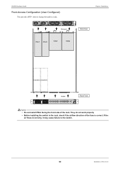
XG2600 Hardware Guide Front-Access Configuration (User Configured) The port side (SFP+ slots) is correct. They do not work properly • Before installing the switch in a rack. Chapter 2 Installation Exhaust Rack Rear PSU1 PSU2 FAN1 FAN2 (Caution) (Caution) Intake Rack Front XG2600 Caution • Do not install PSUs facing the front side of the fans is facing forward in the rack, check if the airflow direction of the rack. If the air flows incorrectly, it may cause failure to the switch. 33 Installation of the switch
XG2600 Hardware Guide Front-Access Configuration (User Configured) The port side (SFP+ slots) is correct. They do not work properly • Before installing the switch in a rack. Chapter 2 Installation Exhaust Rack Rear PSU1 PSU2 FAN1 FAN2 (Caution) (Caution) Intake Rack Front XG2600 Caution • Do not install PSUs facing the front side of the fans is facing forward in the rack, check if the airflow direction of the rack. If the air flows incorrectly, it may cause failure to the switch. 33 Installation of the switch
Hardware Guide
Page 34
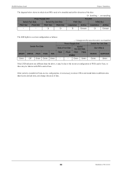
... - - PSU1 Slot PSU2 Slot Installation Airflow Exhaust Installation Airflow Exhaust The LED lights in a correct configuration as follows: - : Unsupported because the unit is necessary to remove PSUs and install them in different slots than factory default ones, and change ... PSU2 Slot - If the switch is installed in Front-Access configuration, it may be due to the incorrect configuration of PSUs and/or Fans, or there may be installed and airflow direction of the switch XG2600 Hardware Guide Chapter 2 Installation The diagram below shows in which ...
... - - PSU1 Slot PSU2 Slot Installation Airflow Exhaust Installation Airflow Exhaust The LED lights in a correct configuration as follows: - : Unsupported because the unit is necessary to remove PSUs and install them in different slots than factory default ones, and change ... PSU2 Slot - If the switch is installed in Front-Access configuration, it may be due to the incorrect configuration of PSUs and/or Fans, or there may be installed and airflow direction of the switch XG2600 Hardware Guide Chapter 2 Installation The diagram below shows in which ...
Hardware Guide
Page 35
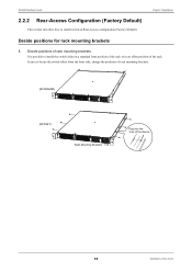
Decide positions of the rack. XG2600 Hardware Guide 2.2.2 Rear-Access Configuration (Factory Default) This section describes how to locate the switch offset from the front side, change the positions of rack mounting brackets. [STANDARD] XG2600 [OFFSET] XG2600 Rack Mounting Brackets Plug into the hole of the device. 35 Installation of the switch It is possible...
Decide positions of the rack. XG2600 Hardware Guide 2.2.2 Rear-Access Configuration (Factory Default) This section describes how to locate the switch offset from the front side, change the positions of rack mounting brackets. [STANDARD] XG2600 [OFFSET] XG2600 Rack Mounting Brackets Plug into the hole of the device. 35 Installation of the switch It is possible...
Hardware Guide
Page 38
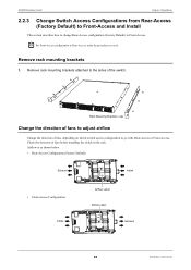
... Brackets Change the direction of fans to adjust airflow Change the direction of fans, depending on which switch access configuration to the sides of the switch. XG2600 Hardware Guide Chapter 2 Installation 2.2.3 Change Switch Access Configurations from Rear-Access (Factory Default) to Front-Access and Install This section describes how to change Rear-Access...
... Brackets Change the direction of fans to adjust airflow Change the direction of fans, depending on which switch access configuration to the sides of the switch. XG2600 Hardware Guide Chapter 2 Installation 2.2.3 Change Switch Access Configurations from Rear-Access (Factory Default) to Front-Access and Install This section describes how to change Rear-Access...
Hardware Guide
Page 41
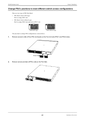
Remove screws and take off PSU units on the Fan Unit side (PSU1 and PSU2 slots). XG2600 Vents with Logo) Put it to empty PSU2 slot right next to PSU1 slot. Remove screws to take off two PSU slot bezels on the ...; PSU Bezel (Vents with Logo Vents without Logo) Put it to empty PSU1 slot. • PSU Bezel (Vents without Logo The procedure to change PSU configurations is shown below. 1. Screw SR-X526R1 XG2600 2. XG2600 Hardware Guide Chapter 2 Installation Change PSU's positions to meet different switch access...
Remove screws and take off PSU units on the Fan Unit side (PSU1 and PSU2 slots). XG2600 Vents with Logo) Put it to empty PSU2 slot right next to PSU1 slot. Remove screws to take off two PSU slot bezels on the ...; PSU Bezel (Vents with Logo Vents without Logo) Put it to empty PSU1 slot. • PSU Bezel (Vents without Logo The procedure to change PSU configurations is shown below. 1. Screw SR-X526R1 XG2600 2. XG2600 Hardware Guide Chapter 2 Installation Change PSU's positions to meet different switch access...
Hardware Guide
Page 43
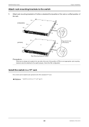
...device. Reference " Install the switch in the EIA standard 19" rack. Check the PSU configuration. XG2600 Hardware Guide Chapter 2 Installation Attach rack mounting brackets to the switch properly. XG2600 Rack Mounting Brackets Precautions PSUs have to fit either a standard front position of the rack or... a offset position of the rack. [STANDARD] XG2600 [OFFSET] Plug into the hole of the rack. Attach ...
...device. Reference " Install the switch in the EIA standard 19" rack. Check the PSU configuration. XG2600 Hardware Guide Chapter 2 Installation Attach rack mounting brackets to the switch properly. XG2600 Rack Mounting Brackets Precautions PSUs have to fit either a standard front position of the rack or... a offset position of the rack. [STANDARD] XG2600 [OFFSET] Plug into the hole of the rack. Attach ...
Hardware Guide
Page 51
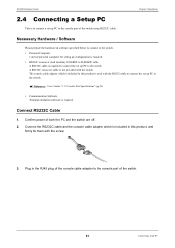
... 1. Reference User's Guide "1.1.5 Console Port Specifications" (pg.29) • Communication Software Terminal emulation software is required to connect the set up configuration is required. • RS232C crossover (null modem), D-SUB9F to D-SUB9F cable A RS232C cable is required. Confirm power of the switch. 51...Personal Computer 1 unit of personal computer for setting up PC to the console port of the console cable adapter to the switch. XG2600 Hardware Guide 2.4 Connecting a Setup PC This is not provided with the switch. The console cable adapter which is included in this ...
... 1. Reference User's Guide "1.1.5 Console Port Specifications" (pg.29) • Communication Software Terminal emulation software is required to connect the set up configuration is required. • RS232C crossover (null modem), D-SUB9F to D-SUB9F cable A RS232C cable is required. Confirm power of the switch. 51...Personal Computer 1 unit of personal computer for setting up PC to the console port of the console cable adapter to the switch. XG2600 Hardware Guide 2.4 Connecting a Setup PC This is not provided with the switch. The console cable adapter which is included in this ...