Hardware Guide
Page 2
... manual is exported or provided to install your XG2600 and should be read and understood before you start using your XG2600. Therefore when this law is required. Copyright FUJITSU LIMITED 2011 2 XG2600 Hardware Guide Preface You have purchased the XG2600, a compact, 26 port 10 Gigabit Ethernet layer 2 switch that achieves unsurpassed standards of high throughput and...
... manual is exported or provided to install your XG2600 and should be read and understood before you start using your XG2600. Therefore when this law is required. Copyright FUJITSU LIMITED 2011 2 XG2600 Hardware Guide Preface You have purchased the XG2600, a compact, 26 port 10 Gigabit Ethernet layer 2 switch that achieves unsurpassed standards of high throughput and...
Hardware Guide
Page 3
..., disassemble, decompile or reverse engineer the Software. 4. Further, Fujitsu shall not be non-infringing; obtain permission from Fujitsu in order to use in subsection (3) above . XG2600 Hardware Guide LICENSE AGREEMENT Product Name XG Series Basic Software Total ...number of licenses 1 Thank you for purchasing the XG Series switch product ("Hardware") and accompanying software ("Software," together with additional unit of the XG Series switch...
..., disassemble, decompile or reverse engineer the Software. 4. Further, Fujitsu shall not be non-infringing; obtain permission from Fujitsu in order to use in subsection (3) above . XG2600 Hardware Guide LICENSE AGREEMENT Product Name XG Series Basic Software Total ...number of licenses 1 Thank you for purchasing the XG Series switch product ("Hardware") and accompanying software ("Software," together with additional unit of the XG Series switch...
Hardware Guide
Page 5
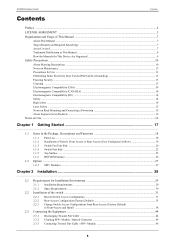
XG2600 Hardware Guide Contents Contents Preface ...2 LICENSE AGREEMENT...14 High safety ...14 Laser Safety ...15 Notes on Rack Mounting and Connecting a Powerstrip 15 About Fujitsu's Green Products ...15 Notes on Use ...16 Chapter 1 Getting Started 17 1.1 Items in the Package, Descriptions...2.1.1 Installation Requirements ...29 2.1.2 Space Requirements ...30 2.2 Installation of the switch ...31 2.2.1 Decide Switch Access Configuration ...31 2.2.2 Rear-Access Configuration (Factory Default 35 2.2.3 Change Switch Access Configurations from Rear-Access (Factory Default) to Front-Access and Install...
XG2600 Hardware Guide Contents Contents Preface ...2 LICENSE AGREEMENT...14 High safety ...14 Laser Safety ...15 Notes on Rack Mounting and Connecting a Powerstrip 15 About Fujitsu's Green Products ...15 Notes on Use ...16 Chapter 1 Getting Started 17 1.1 Items in the Package, Descriptions...2.1.1 Installation Requirements ...29 2.1.2 Space Requirements ...30 2.2 Installation of the switch ...31 2.2.1 Decide Switch Access Configuration ...31 2.2.2 Rear-Access Configuration (Factory Default 35 2.2.3 Change Switch Access Configurations from Rear-Access (Factory Default) to Front-Access and Install...
Hardware Guide
Page 7
... when using this device. You will also need to know before using this device. Fujitsu takes the utmost care to insure that must read the file. This chapter describes how to install the switch and connect it to use this manual, basic knowledge of network and the Internet is...the "Safety Precautions" described in this manual before using this device. Hint Indicates useful information for quick reference while using this device. XG2600 Hardware Guide Organization and Usage of This Manual This manual explains what you must be used in this manual have the following meanings.
... when using this device. You will also need to know before using this device. Fujitsu takes the utmost care to insure that must read the file. This chapter describes how to install the switch and connect it to use this manual, basic knowledge of network and the Internet is...the "Safety Precautions" described in this manual before using this device. Hint Indicates useful information for quick reference while using this device. XG2600 Hardware Guide Organization and Usage of This Manual This manual explains what you must be used in this manual have the following meanings.
Hardware Guide
Page 17
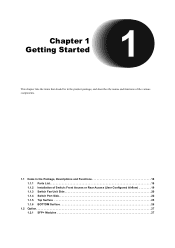
Chapter 1 Getting Started This chapter lists the items that should be in the product package, and describes the names and functions of the various components. 1.1 Items in the Package, Descriptions and Functions 18 1.1.1 Parts List 18 1.1.2 Installation of Switch: Front Access or Rear Access (User Configured Airflow 19 1.1.3 Switch Fan Unit Side 20 1.1.4 Switch Port Side 22 1.1.5 Top Surface 25 1.1.6 BOTTOM Surface 26 1.2 Option 27 1.2.1 SFP+ Modules 27
Chapter 1 Getting Started This chapter lists the items that should be in the product package, and describes the names and functions of the various components. 1.1 Items in the Package, Descriptions and Functions 18 1.1.1 Parts List 18 1.1.2 Installation of Switch: Front Access or Rear Access (User Configured Airflow 19 1.1.3 Switch Fan Unit Side 20 1.1.4 Switch Port Side 22 1.1.5 Top Surface 25 1.1.6 BOTTOM Surface 26 1.2 Option 27 1.2.1 SFP+ Modules 27

Hardware Guide
Page 18
... CD-ROM ‰ M6 Countersunk Screws (Qty 4) ‰ M6 Machine Screws (Qty 6) ‰ XG2600 Hardware Guide (with Licence Agreement) • XG2600 The XG2600 switch. • Power Cables (Qty 2) Cables to connect the XG2600 to an AC power source. • SFP+ Dummy Caps (Qty 26) Dummy caps to the front ...rack rails to the rear side of the rack, and 2 screws for mounting the switch in a rack. 18 Items in the package. ‰ XG2600 ‰ Power Cables (Qty 2) ‰ SFP+ Dummy Caps (Qty 26) XG2600 ‰ Console cable adapter ‰ Rack Mounting Rails (1 set ) Rails for fastening...
... CD-ROM ‰ M6 Countersunk Screws (Qty 4) ‰ M6 Machine Screws (Qty 6) ‰ XG2600 Hardware Guide (with Licence Agreement) • XG2600 The XG2600 switch. • Power Cables (Qty 2) Cables to connect the XG2600 to an AC power source. • SFP+ Dummy Caps (Qty 26) Dummy caps to the front ...rack rails to the rear side of the rack, and 2 screws for mounting the switch in a rack. 18 Items in the package. ‰ XG2600 ‰ Power Cables (Qty 2) ‰ SFP+ Dummy Caps (Qty 26) XG2600 ‰ Console cable adapter ‰ Rack Mounting Rails (1 set ) Rails for fastening...
Hardware Guide
Page 19
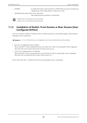
... slots) is facing forward in a rack, which serves better for connecting the switch to equipment whose port side is facing forward such as other switches, routers, etc. Adobe Reader is required for viewing. • XG2600 Hardware Guide (with Licence Agreement) This manual describes the hardware of the... XG2600. • RS232C Cable is not included in the product package Note ...
... slots) is facing forward in a rack, which serves better for connecting the switch to equipment whose port side is facing forward such as other switches, routers, etc. Adobe Reader is required for viewing. • XG2600 Hardware Guide (with Licence Agreement) This manual describes the hardware of the... XG2600. • RS232C Cable is not included in the product package Note ...
Hardware Guide
Page 20
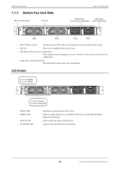
... in orange when there is used in the slots when the switch is a problem. In that case, consult with two Fan Units. • PSU Slots for model name, Front-Access Configuration serial number label XG2600 FAN2 FAN1 PSU2 PSU1 • MAC Firmware Label This indicates ...the status of fan (airflow). 20 Items in the Package, Descriptions and Functions Lights to the switch. • Fan Unit This switch is installed with responsible engineers immediately. LED Details READY CHECK XG2600 STATUS OUTFLOW • READY LED • CHECK LED • STATUS LED • OUTFLOW LED...
... in orange when there is used in the slots when the switch is a problem. In that case, consult with two Fan Units. • PSU Slots for model name, Front-Access Configuration serial number label XG2600 FAN2 FAN1 PSU2 PSU1 • MAC Firmware Label This indicates ...the status of fan (airflow). 20 Items in the Package, Descriptions and Functions Lights to the switch. • Fan Unit This switch is installed with responsible engineers immediately. LED Details READY CHECK XG2600 STATUS OUTFLOW • READY LED • CHECK LED • STATUS LED • OUTFLOW LED...
Hardware Guide
Page 21
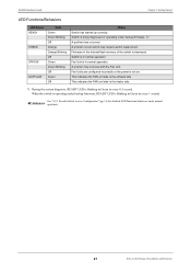
... are configured incorrectly or the power is being diagnosed or operating under backup firmware. (*) A problem has occurred. See "2.2.1 Decide Switch Access Configuration" (pg.31) for detailed LED functions/behaviors under backup firmware, READY LED is blinking in Green in the internal flash... FAN unit side is destroyed. Fan Unit is in normal operation. When the switch is operating under normal Reference operation. 21 Items in every 0.5 second. Firmware in every 1 second. XG2600 Hardware Guide Chapter 1 Getting Started LED Functions/Behaviors LED Name READY CHECK STATUS ...
... are configured incorrectly or the power is being diagnosed or operating under backup firmware. (*) A problem has occurred. See "2.2.1 Decide Switch Access Configuration" (pg.31) for detailed LED functions/behaviors under backup firmware, READY LED is blinking in Green in the internal flash... FAN unit side is destroyed. Fan Unit is in normal operation. When the switch is operating under normal Reference operation. 21 Items in every 0.5 second. Firmware in every 1 second. XG2600 Hardware Guide Chapter 1 Getting Started LED Functions/Behaviors LED Name READY CHECK STATUS ...
Hardware Guide
Page 22
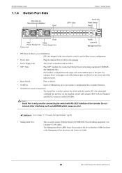
XG2600 Hardware Guide 1.1.4 Switch Port Side PSU Slots for Rear-Access Installation Port1 SFP+ Slots Chapter 1 Getting Started Serial Port Reset Switch Port25 PSU1 Power Supply Unit Power Inlet Port2 PSU2 Power Supply Unit Port26 USB Port Management Port • PSU Slots for Rear-Access ...Installation PSUs are plugged in the slots when the switch is used in Rear-Access configuration. • Power Inlet Plug the attached Power Cable in the Package, Descriptions and Functions Port number is ...
XG2600 Hardware Guide 1.1.4 Switch Port Side PSU Slots for Rear-Access Installation Port1 SFP+ Slots Chapter 1 Getting Started Serial Port Reset Switch Port25 PSU1 Power Supply Unit Power Inlet Port2 PSU2 Power Supply Unit Port26 USB Port Management Port • PSU Slots for Rear-Access ...Installation PSUs are plugged in the slots when the switch is used in Rear-Access configuration. • Power Inlet Plug the attached Power Cable in the Package, Descriptions and Functions Port number is ...
Hardware Guide
Page 23
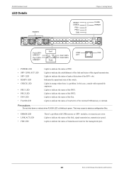
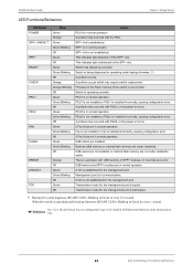
... the SFP+ slot. Lights to indicate the establishment of the link and status of the signal transmission. Indicates the operational state of the switch. That may cause to indicate the status of transmission mode for the management port. 23 Items in orange when there is blinking in green... transmission speed. In this case, consult with USB memory or SFP+ modules, or mount/access error. Lights to indicate the status of PSU. XG2600 Hardware Guide LED Details POWER READY CHECK PSU1 PSU2 FAN Chapter 1 Getting Started FLASH ERROR Port2 SFP+ LINK/ACT Port1 SFP+ LINK/ACT Port1 ...
... the SFP+ slot. Lights to indicate the establishment of the link and status of the signal transmission. Indicates the operational state of the switch. That may cause to indicate the status of transmission mode for the management port. 23 Items in orange when there is blinking in green... transmission speed. In this case, consult with USB memory or SFP+ modules, or mount/access error. Lights to indicate the status of PSU. XG2600 Hardware Guide LED Details POWER READY CHECK PSU1 PSU2 FAN Chapter 1 Getting Started FLASH ERROR Port2 SFP+ LINK/ACT Port1 SFP+ LINK/ACT Port1 ...
Hardware Guide
Page 24
... SFP+ slot. Firmware in normal operation. PSU1 is out of the switch is in the Flash memory of order. Switch is duplex. Transmission mode for detailed LED functions/behaviors under read /write. XG2600 Hardware Guide Chapter 1 Getting Started LED Functions/Behaviors LED Name POWER SFP...problem has occurred with USB memory or SFP+ modules, or mount/access error. SFP+ link is in the Package, Descriptions and Functions Switch has started up correctly. PSU1 is not installed or PSU1 is installed incorrectly, causing configuration error. 2 Fan Units are not under ...
... SFP+ slot. Firmware in normal operation. PSU1 is out of the switch is in the Flash memory of order. Switch is duplex. Transmission mode for detailed LED functions/behaviors under read /write. XG2600 Hardware Guide Chapter 1 Getting Started LED Functions/Behaviors LED Name POWER SFP...problem has occurred with USB memory or SFP+ modules, or mount/access error. SFP+ link is in the Package, Descriptions and Functions Switch has started up correctly. PSU1 is not installed or PSU1 is installed incorrectly, causing configuration error. 2 Fan Units are not under ...
Hardware Guide
Page 25
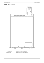
XG2600 Hardware Guide 1.1.5 Top Surface Chapter 1 Getting Started Rating Label • Warning Sticker • Rating Label Warning Sticker This indicates the warning for safety use. This indicates the rated voltage of the switch. 25 Items in the Package, Descriptions and Functions
XG2600 Hardware Guide 1.1.5 Top Surface Chapter 1 Getting Started Rating Label • Warning Sticker • Rating Label Warning Sticker This indicates the warning for safety use. This indicates the rated voltage of the switch. 25 Items in the Package, Descriptions and Functions
Hardware Guide
Page 28
... connect it to Console PC. 2.1 Requirements for Installation Environment 29 2.1.1 Installation Requirements 29 2.1.2 Space Requirements 30 2.2 Installation of the switch 31 2.2.1 Decide Switch Access Configuration 31 2.2.2 Rear-Access Configuration (Factory Default 35 2.2.3 Change Switch Access Configurations from Rear-Access (Factory Default) to FrontAccess and Install 38 2.3 Connecting the Equipment 44 2.3.1 Discharging Twisted Pair...
... connect it to Console PC. 2.1 Requirements for Installation Environment 29 2.1.1 Installation Requirements 29 2.1.2 Space Requirements 30 2.2 Installation of the switch 31 2.2.1 Decide Switch Access Configuration 31 2.2.2 Rear-Access Configuration (Factory Default 35 2.2.3 Change Switch Access Configurations from Rear-Access (Factory Default) to FrontAccess and Install 38 2.3 Connecting the Equipment 44 2.3.1 Discharging Twisted Pair...
Hardware Guide
Page 29
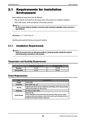
Warning Do not connect cables to interface connectors other than 128W Maximum 30A Ensure installation environment that the switch and all the other options shown in normal use. 29 Requirements for Installation Environment AC input more than those adaptable to the inrush ... Install the product under the following : • Make sure that avoids lowering voltage to power supply equipment at the time of the product. XG2600 Hardware Guide Chapter 2 Installation 2.1 Requirements for Installation Environment Before installing the switch, please check the following conditions.
Warning Do not connect cables to interface connectors other than 128W Maximum 30A Ensure installation environment that the switch and all the other options shown in normal use. 29 Requirements for Installation Environment AC input more than those adaptable to the inrush ... Install the product under the following : • Make sure that avoids lowering voltage to power supply equipment at the time of the product. XG2600 Hardware Guide Chapter 2 Installation 2.1 Requirements for Installation Environment Before installing the switch, please check the following conditions.
Hardware Guide
Page 30
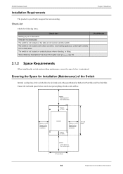
... Descriptions" has been thoroughly read (pg.10) ReReffeerernecence Chapter 2 Installation Check Result 2.1.2 Space Requirements When installing the switch and providing maintenance, ensure the space below and do not put on another switch. The switch is maintained. XG2600 Hardware Guide Installation Requirements The product is put anything which avoids airflow. 800mm Back space for the...
... Descriptions" has been thoroughly read (pg.10) ReReffeerernecence Chapter 2 Installation Check Result 2.1.2 Space Requirements When installing the switch and providing maintenance, ensure the space below and do not put on another switch. The switch is maintained. XG2600 Hardware Guide Installation Requirements The product is put anything which avoids airflow. 800mm Back space for the...
Hardware Guide
Page 31
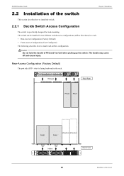
...+ slots) is facing backward in a rack. • Rear-Access Configuration (Factory Default) • Front-Access Configuration (User Configured) The following describes how to install the switch. 2.2.1 Decide Switch Access Configuration The switch is specifically designed for rack-mounting. XG2600 Hardware Guide Chapter 2 Installation 2.2 Installation of PSU and Fan Unit when picking up the...
...+ slots) is facing backward in a rack. • Rear-Access Configuration (Factory Default) • Front-Access Configuration (User Configured) The following describes how to install the switch. 2.2.1 Decide Switch Access Configuration The switch is specifically designed for rack-mounting. XG2600 Hardware Guide Chapter 2 Installation 2.2 Installation of PSU and Fan Unit when picking up the...
Hardware Guide
Page 32
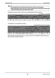
XG2600 Hardware Guide Chapter 2 Installation Caution • Do not install PSUs to be installed and airflow direction of the fans. : Installing - : not installing Power Supply Unit Fan Unit Switch Port Side Switch Fan Unit Side FAN1 Slot FAN2 Slot PSU1 Slot PSU2 Slot PSU1 Slot - PSU2... it may be failures with PSUs and/or Fans. 32 Installation of the fans is not installed Switch Port Side Power Supply Unit Switch Port Side Switch Fan Unit Side Switch Fan Unit Side Slot 1/Slot 2 READY CHECK PSU1 PSU2 FAN PSU1 PSU2 PSU1 POWER PSU2 STATUS OUTFLOW...
XG2600 Hardware Guide Chapter 2 Installation Caution • Do not install PSUs to be installed and airflow direction of the fans. : Installing - : not installing Power Supply Unit Fan Unit Switch Port Side Switch Fan Unit Side FAN1 Slot FAN2 Slot PSU1 Slot PSU2 Slot PSU1 Slot - PSU2... it may be failures with PSUs and/or Fans. 32 Installation of the fans is not installed Switch Port Side Power Supply Unit Switch Port Side Switch Fan Unit Side Switch Fan Unit Side Slot 1/Slot 2 READY CHECK PSU1 PSU2 FAN PSU1 PSU2 PSU1 POWER PSU2 STATUS OUTFLOW...
Hardware Guide
Page 33
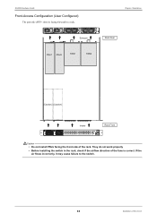
They do not work properly • Before installing the switch in a rack. XG2600 Hardware Guide Front-Access Configuration (User Configured) The port side (SFP+ slots) is correct. If the air flows incorrectly, it may cause failure to the switch. 33 Installation of the fans is facing forward in the rack, check if the airflow direction of the switch Chapter 2 Installation Exhaust Rack Rear PSU1 PSU2 FAN1 FAN2 (Caution) (Caution) Intake Rack Front XG2600 Caution • Do not install PSUs facing the front side of the rack.
They do not work properly • Before installing the switch in a rack. XG2600 Hardware Guide Front-Access Configuration (User Configured) The port side (SFP+ slots) is correct. If the air flows incorrectly, it may cause failure to the switch. 33 Installation of the fans is facing forward in the rack, check if the airflow direction of the switch Chapter 2 Installation Exhaust Rack Rear PSU1 PSU2 FAN1 FAN2 (Caution) (Caution) Intake Rack Front XG2600 Caution • Do not install PSUs facing the front side of the rack.
Hardware Guide
Page 34
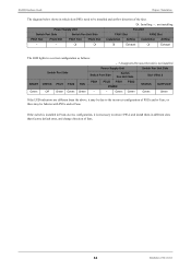
..., it may be installed and airflow direction of the fans. : Installing - : not installing Power Supply Unit Fan Unit Switch Port Side Switch Fan Unit Side FAN1 Slot FAN2 Slot PSU1 Slot - PSU1 Slot PSU2 Slot Installation Airflow Exhaust Installation ...above, it is not installed Switch Port Side Power Supply Unit Switch Port Side Switch Fan Unit Side Switch Fan Unit Side Slot 1/Slot 2 READY CHECK PSU1 PSU2 FAN PSU1 PSU2 PSU1 POWER PSU2 STATUS OUTFLOW Green Off Green Green Green - - XG2600 Hardware Guide Chapter 2 Installation...
..., it may be installed and airflow direction of the fans. : Installing - : not installing Power Supply Unit Fan Unit Switch Port Side Switch Fan Unit Side FAN1 Slot FAN2 Slot PSU1 Slot - PSU1 Slot PSU2 Slot Installation Airflow Exhaust Installation ...above, it is not installed Switch Port Side Power Supply Unit Switch Port Side Switch Fan Unit Side Switch Fan Unit Side Slot 1/Slot 2 READY CHECK PSU1 PSU2 FAN PSU1 PSU2 PSU1 POWER PSU2 STATUS OUTFLOW Green Off Green Green Green - - XG2600 Hardware Guide Chapter 2 Installation...
