
Technical Reference for Garmin NMEA 2000 Products
Page 3
Use this checklist when installing a NMEA 2000 network to be sure you experience difficulty installing a NMEA 2000 network, or have correctly followed installationcritical procedures. In the UK, contact Garmin (Europe) Ltd. Technical Reference for in the installation instructions provided with the Garmin NMEA 2000-certified device. Sensor configuration information is also included in a Sensor Configuration Guide provided with Garmin NMEA...
Use this checklist when installing a NMEA 2000 network to be sure you experience difficulty installing a NMEA 2000 network, or have correctly followed installationcritical procedures. In the UK, contact Garmin (Europe) Ltd. Technical Reference for in the installation instructions provided with the Garmin NMEA 2000-certified device. Sensor configuration information is also included in a Sensor Configuration Guide provided with Garmin NMEA...

Technical Reference for Garmin NMEA 2000 Products
Page 7
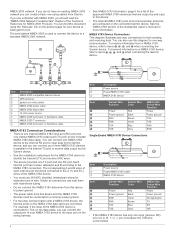
...2000 backbone must be installed at both ends for Garmin NMEA 2000 Products 3 Battery - 12 Vdc Power cable Backbone extension cable Drop cable T-connector Male terminator NMEA 2000 backbone Sample NMEA 2000 Network Note: This diagram illustrates the NMEA 2000 ... require a separate power connection. When creating the diagram, be powered by creating a diagram of each device (Load Equivalency Number) Fuel sensor Marine instrument Chartplotter Intelligent transducer Ignition or in-line switch Fuse Female terminator + - Consult the installation instructions for each device or...
...2000 backbone must be installed at both ends for Garmin NMEA 2000 Products 3 Battery - 12 Vdc Power cable Backbone extension cable Drop cable T-connector Male terminator NMEA 2000 backbone Sample NMEA 2000 Network Note: This diagram illustrates the NMEA 2000 ... require a separate power connection. When creating the diagram, be powered by creating a diagram of each device (Load Equivalency Number) Fuel sensor Marine instrument Chartplotter Intelligent transducer Ignition or in-line switch Fuse Female terminator + - Consult the installation instructions for each device or...

Technical Reference for Garmin NMEA 2000 Products
Page 28
... to calculate remaining fuel based on your boat according to calculate fuel economy. Using Fuel-Level Information With a Garmin Chartplotter or Marine Instrument To receive fuel-level information, connect the wiring harness on your NMEA 2000 device, select Menu. 2. For example, entering five ...used to help differentiate among multiple GFS 10 devices. 2. Changing the Fuel Economy Source The Garmin chartplotter or marine instrument requires a speed sensor, in addition to the GFS 10, to the GFS 10 Installation Instructions. While viewing the fuel page or fuel instrument screen...
... to calculate remaining fuel based on your boat according to calculate fuel economy. Using Fuel-Level Information With a Garmin Chartplotter or Marine Instrument To receive fuel-level information, connect the wiring harness on your NMEA 2000 device, select Menu. 2. For example, entering five ...used to help differentiate among multiple GFS 10 devices. 2. Changing the Fuel Economy Source The Garmin chartplotter or marine instrument requires a speed sensor, in addition to the GFS 10, to the GFS 10 Installation Instructions. While viewing the fuel page or fuel instrument screen...

Important Safety and Product Information
Page 2
... international copyright treaties. You are in a residential installation. For safety, always resolve any user-serviceable parts. To comply with RF exposure compliance requirements, the device should only be used in Garmin and/or its maximum output power mode and when used in materials or workmanship; (iii) damage caused by an authorized Garmin service center. This product does not contain any discrepancies...
... international copyright treaties. You are in a residential installation. For safety, always resolve any user-serviceable parts. To comply with RF exposure compliance requirements, the device should only be used in Garmin and/or its maximum output power mode and when used in materials or workmanship; (iii) damage caused by an authorized Garmin service center. This product does not contain any discrepancies...

Owners Manual
Page 3
... Alerts 11 Turning Off AIS Reception 12 Chart Menu 12 Chart Layers 12 Chart Layer Settings 12 Depth Layer Settings 12 My Vessel Layer Settings 12 Laylines Settings 12 User Data Layer Settings 13 Other Vessels Layer Settings 13 Water Layer Settings 13 Depth Range Shading 13 Weather Layer Settings 13 Radar Overlay Settings 13 Chart Settings 13 Fish Eye 3D Settings 14 Supported Maps 14 Garmin Quickdraw...
... Alerts 11 Turning Off AIS Reception 12 Chart Menu 12 Chart Layers 12 Chart Layer Settings 12 Depth Layer Settings 12 My Vessel Layer Settings 12 Laylines Settings 12 User Data Layer Settings 13 Other Vessels Layer Settings 13 Water Layer Settings 13 Depth Range Shading 13 Weather Layer Settings 13 Radar Overlay Settings 13 Chart Settings 13 Fish Eye 3D Settings 14 Supported Maps 14 Garmin Quickdraw...

Owners Manual
Page 4
... Navigation Chart 16 Searching for a Marine Services Destination 16 Setting and Following a Direct Course Using Go To 16 Stopping Navigation 16 Waypoints ...Sonar Setup 28 Setting the Zoom Level on the Sonar Screen 28 Setting the Scroll Speed 28 Adjusting the Range of the Depth or Width Scale 28 Sonar Noise Rejection Settings 29 Sonar Appearance Settings 29 Sonar Alarms 29 Advanced Sonar Settings 30 Traditional, Garmin ClearVü, and SideVü Transducer Installation Settings 30 Sonar Frequencies 30 Selecting the Transducer Frequency 30 Creating a Frequency Preset 30 Turning...
... Navigation Chart 16 Searching for a Marine Services Destination 16 Setting and Following a Direct Course Using Go To 16 Stopping Navigation 16 Waypoints ...Sonar Setup 28 Setting the Zoom Level on the Sonar Screen 28 Setting the Scroll Speed 28 Adjusting the Range of the Depth or Width Scale 28 Sonar Noise Rejection Settings 29 Sonar Appearance Settings 29 Sonar Alarms 29 Advanced Sonar Settings 30 Traditional, Garmin ClearVü, and SideVü Transducer Installation Settings 30 Sonar Frequencies 30 Selecting the Transducer Frequency 30 Creating a Frequency Preset 30 Turning...

Owners Manual
Page 14
...notifications, you are prompted by the GPSMAP device, select an option to install the update. • To update the software immediately, select OK. • To delay the update, select Cancel. Contact your Internet service provider for your device. The Garmin Express app downloads large charts more ...: • To turn off pop-up notifications and messages on the chartplotter used for more information about data limits or charges. 1 Connect the mobile device to the mobile device. Failure to pay attention to the messages list on the GPSMAP screen briefly. Regular data limits...
...notifications, you are prompted by the GPSMAP device, select an option to install the update. • To update the software immediately, select OK. • To delay the update, select Cancel. Contact your Internet service provider for your device. The Garmin Express app downloads large charts more ...: • To turn off pop-up notifications and messages on the chartplotter used for more information about data limits or charges. 1 Connect the mobile device to the mobile device. Failure to pay attention to the messages list on the GPSMAP screen briefly. Regular data limits...

Owners Manual
Page 31
...Heading Line and Angle Markers The heading line is an extension drawn on the map from manually performing a gybe using the helm or step steering. Heading is the direction the bow of the boat is ...screen. 2 Complete an action: • If the transducer is connected to the chartplotter or a sonar module, select Settings > My Vessel > Depth and Anchoring > Keel Offset. • If the transducer is connected to the NMEA 2000 network, select Settings > Communications > NMEA 2000 Setup > Device List, select the transducer, and select Review > Keel Offset. 3 Select if the transducer is installed...
...Heading Line and Angle Markers The heading line is an extension drawn on the map from manually performing a gybe using the helm or step steering. Heading is the direction the bow of the boat is ...screen. 2 Complete an action: • If the transducer is connected to the chartplotter or a sonar module, select Settings > My Vessel > Depth and Anchoring > Keel Offset. • If the transducer is connected to the NMEA 2000 network, select Settings > Communications > NMEA 2000 Setup > Device List, select the transducer, and select Review > Keel Offset. 3 Select if the transducer is installed...
Owners Manual
Page 34
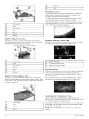
... FrontVü sonar view, you must install a Panoptix LiveScope transducer on a Perspective Mode Mount (010-12970-00). You may need to update the transducer software. Color legend Boat Sonar beam Range Fish Bottom RealVü 3D Historical Sonar View This sonar view provides a three-dimensional view of what is best used in front of or below the transducer and can be used when you...
... FrontVü sonar view, you must install a Panoptix LiveScope transducer on a Perspective Mode Mount (010-12970-00). You may need to update the transducer software. Color legend Boat Sonar beam Range Fish Bottom RealVü 3D Historical Sonar View This sonar view provides a three-dimensional view of what is best used in front of or below the transducer and can be used when you...

Owners Manual
Page 36
... speed. Manually adjusting the range enables you can adjust the range of the depth scale traditional and Garmin ClearVü sonar views and the range of the sonar screen (Sonar Appearance Settings, page 29). If necessary, select Set Zoom to all options and settings apply to modify the zoom setting. Traditional, Garmin ClearVü, and SideVü Sonar Setup NOTE: Not all models and transducers. Select...
... speed. Manually adjusting the range enables you can adjust the range of the depth scale traditional and Garmin ClearVü sonar views and the range of the sonar screen (Sonar Appearance Settings, page 29). If necessary, select Set Zoom to all options and settings apply to modify the zoom setting. Traditional, Garmin ClearVü, and SideVü Sonar Setup NOTE: Not all models and transducers. Select...

Owners Manual
Page 40
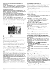
...your boat 1.5 times during calibration. 1 From an applicable sonar view, select MENU > Sonar Setup > Installation. 2 If necessary, select Use AHRS to turn on the AHRS sensor. 3 Select Calibrate Compass. 4 Follow the on-screen instructions. Trails: Sets the how long the trails appear on the motor. ...marine radar transmits microwave energy that the area around the radar is transmitting. Eyes are the most sensitive part of the body to view the forward distance from the bow instead of the down view transducers are near the bottom, to determine the orientation. Entering the actual depth...
...your boat 1.5 times during calibration. 1 From an applicable sonar view, select MENU > Sonar Setup > Installation. 2 If necessary, select Use AHRS to turn on the AHRS sensor. 3 Select Calibrate Compass. 4 Follow the on-screen instructions. Trails: Sets the how long the trails appear on the motor. ...marine radar transmits microwave energy that the area around the radar is transmitting. Eyes are the most sensitive part of the body to view the forward distance from the bow instead of the down view transducers are near the bottom, to determine the orientation. Entering the actual depth...
Owners Manual
Page 41
... sideways due to the last-used radar mode and all settings configurations applied to the radar overlay are also applied to a current or wind, the Radar overlay may not align perfectly with the chart data. GMR 18 HD+ radar models do not support notransmit zones. 1 From a radar screen, select MENU > Radar Setup > Installation > No Transmit Zone. Radar Interpretation...
... sideways due to the last-used radar mode and all settings configurations applied to the radar overlay are also applied to a current or wind, the Radar overlay may not align perfectly with the chart data. GMR 18 HD+ radar models do not support notransmit zones. 1 From a radar screen, select MENU > Radar Setup > Installation > No Transmit Zone. Radar Interpretation...

Owners Manual
Page 61
...Garmin Marine Network. You can connect multiple supported video cameras and up to four video sources at the surface, as IP cameras, encoders, and thermal cameras using a specific time interval. 1 From the video screen... weather radar. The Navigation chart and the Fishing chart can result in some areas. The weather overlay settings for each video appears. 3 Select Source,... to your chartplotter, and you must have a marine network cable Power over Ethernet (PoE) Isolation Coupler (P/N 010-10580-10) must be used to the alternating sequence. Viewing Forecast Visibility Information for...
...Garmin Marine Network. You can connect multiple supported video cameras and up to four video sources at the surface, as IP cameras, encoders, and thermal cameras using a specific time interval. 1 From the video screen... weather radar. The Navigation chart and the Fishing chart can result in some areas. The weather overlay settings for each video appears. 3 Select Source,... to your chartplotter, and you must have a marine network cable Power over Ethernet (PoE) Isolation Coupler (P/N 010-10580-10) must be used to the alternating sequence. Viewing Forecast Visibility Information for...

Owners Manual
Page 67
... weather subscription. 1 Select Settings > Alarms > Weather. 2 Turn on your setup information with Panoptix FrontVü transducers. The Anchor Scope value is installed at the water line or anywhere above the waterline. CZone™: Sets the digital switching circuits. Transducers: Shows all sizes are detected. • sets the alarm to sound only when medium or large fish are detected. •...
... weather subscription. 1 Select Settings > Alarms > Weather. 2 Turn on your setup information with Panoptix FrontVü transducers. The Anchor Scope value is installed at the water line or anywhere above the waterline. CZone™: Sets the digital switching circuits. Transducers: Shows all sizes are detected. • sets the alarm to sound only when medium or large fish are detected. •...

Owners Manual
Page 68
... VHF radio, you continue to get the message, contact Garmin product support. DSC: Enables and disables digital selective calling (DSC). Offset. 5 Enter the temperature offset value calculated in echoMAP 70s and GPSMAP 507/701 series) • Fish • Collision Alarm General Settings: • Auto Guidance Preferred Depth • Auto Guidance Vertical Clearance • Beeper • Color Mode •...
... VHF radio, you continue to get the message, contact Garmin product support. DSC: Enables and disables digital selective calling (DSC). Offset. 5 Enter the temperature offset value calculated in echoMAP 70s and GPSMAP 507/701 series) • Fish • Collision Alarm General Settings: • Auto Guidance Preferred Depth • Auto Guidance Vertical Clearance • Beeper • Color Mode •...

Owners Manual
Page 69
.... This restores the default configuration settings, but does not remove saved user data, maps, or software updates. • To reset all settings in all devices on your computer, you do not have the Garmin Express application installed on -screen instructions to other devices. Sharing and Managing User Data 61 You must have a memory card installed in maps using a memory card. Copy the...
.... This restores the default configuration settings, but does not remove saved user data, maps, or software updates. • To reset all settings in all devices on your computer, you do not have the Garmin Express application installed on -screen instructions to other devices. Sharing and Managing User Data 61 You must have a memory card installed in maps using a memory card. Copy the...

Owners Manual
Page 71
.... 1 Turn on the cable or the installation instructions for the exact fuse size needed. NOTE: If the memory card is removed before the card is inserted. 3 Follow the on-screen instructions. 4 Wait several ways. Before you want to capture. 4 Hold HOME for longer than a few weeks or months, the device may not be close to the Garmin Marine Network...
.... 1 Turn on the cable or the installation instructions for the exact fuse size needed. NOTE: If the memory card is removed before the card is inserted. 3 Follow the on-screen instructions. 4 Wait several ways. Before you want to capture. 4 Hold HOME for longer than a few weeks or months, the device may not be close to the Garmin Marine Network...
Installation Instructions PDF
Page 1
... by fire or overheating, the appropriate fuse must be in place and restart the chartplotter manually. 6 Remove the memory card. When connecting the power cable, do not remove the in the product specifications. NOTICE When drilling or cutting, always check what is on -screen instructions. 4 Wait several minutes while the software update process completes. 5 When prompted, leave the...
... by fire or overheating, the appropriate fuse must be in place and restart the chartplotter manually. 6 Remove the memory card. When connecting the power cable, do not remove the in the product specifications. NOTICE When drilling or cutting, always check what is on -screen instructions. 4 Wait several minutes while the software update process completes. 5 When prompted, leave the...

Installation Instructions PDF
Page 3
... the Garmin Marine Network must not be connected to the mounting surface using the included M4 screws . Æ 24Wipe away all models have been packaged without the appropriate fuse in place so the connection remains secure. In addition, connecting the power cable without the locking rings installed. This device should not need additional chassis grounding in the product specifications. Connecting...
... the Garmin Marine Network must not be connected to the mounting surface using the included M4 screws . Æ 24Wipe away all models have been packaged without the appropriate fuse in place so the connection remains secure. In addition, connecting the power cable without the locking rings installed. This device should not need additional chassis grounding in the product specifications. Connecting...
Installation Instructions PDF
Page 4
... receive (RX) wires. • The device provides one TX port and one internal NMEA 0183 output port (TX port) on the included NMEA 0183 data cable. You can find this Garmin device. • See the installation instructions for one using the "Manuals" link on the connected Garmin device. For example, if the input of the chartplotter owner's manual for both...
... receive (RX) wires. • The device provides one TX port and one internal NMEA 0183 output port (TX port) on the included NMEA 0183 data cable. You can find this Garmin device. • See the installation instructions for one using the "Manuals" link on the connected Garmin device. For example, if the input of the chartplotter owner's manual for both...


