
Technical Reference for Garmin NMEA 2000 Products
Page 3
... two sections provide Parameter Group Number (PGN) information for Garmin chartplotters and marine instruments as well as configuration and PGN information for in the installation instructions provided with each Garmin NMEA 2000-certified sensor. • At the end is also included in -country support information, or contact Garmin (Europe) Ltd. This technical reference provides basic NMEA 2000...
... two sections provide Parameter Group Number (PGN) information for Garmin chartplotters and marine instruments as well as configuration and PGN information for in the installation instructions provided with each Garmin NMEA 2000-certified sensor. • At the end is also included in -country support information, or contact Garmin (Europe) Ltd. This technical reference provides basic NMEA 2000...

Technical Reference for Garmin NMEA 2000 Products
Page 7
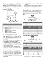
... to the device appropriately. Consult the installation instructions for each device you design a NMEA 2000 network, start by the NMEA 2000 network; Be sure to the backbone with a T-connector. Battery - 12 Vdc Power cable Backbone extension cable Drop cable T-connector Male terminator NMEA 2000 backbone Sample NMEA 2000 Network Note: This diagram illustrates the NMEA 2000 data connections...
... to the device appropriately. Consult the installation instructions for each device you design a NMEA 2000 network, start by the NMEA 2000 network; Be sure to the backbone with a T-connector. Battery - 12 Vdc Power cable Backbone extension cable Drop cable T-connector Male terminator NMEA 2000 backbone Sample NMEA 2000 Network Note: This diagram illustrates the NMEA 2000 data connections...

Technical Reference for Garmin NMEA 2000 Products
Page 28
...Tank-set the fuel level to the maximum capacity. • Add Fuel to Boat-specify the amount of fuel added. • Set ...reset the fuel-level calibration: 1. Important: When using the GFS 10 to calculate remaining fuel based on the fuel-flow rate, you must be powered...full tank). Using Fuel-Level Information With a Garmin Chartplotter or Marine Instrument To receive fuel-level information, connect the wiring harness on the NMEA 2000 device configuration screen to help ...GPS Speed or Water Speed to specify which speed sensor is used on the unit to the GFS 10 Installation Instructions.
...Tank-set the fuel level to the maximum capacity. • Add Fuel to Boat-specify the amount of fuel added. • Set ...reset the fuel-level calibration: 1. Important: When using the GFS 10 to calculate remaining fuel based on the fuel-flow rate, you must be powered...full tank). Using Fuel-Level Information With a Garmin Chartplotter or Marine Instrument To receive fuel-level information, connect the wiring harness on the NMEA 2000 device configuration screen to help ...GPS Speed or Water Speed to specify which speed sensor is used on the unit to the GFS 10 Installation Instructions.

Important Safety and Product Information
Page 2
... from the GPS device. • Consult the dealer or an experienced radio/TV technician for any interference received, including interference that may cause harmful interference to radio communications if not installed and used in accordance ...support.garmin.com to obtain warranty service. Hearing Damage Warning Listening to the stereo at its sole discretion and subject to applicable laws, repair or replace your product with comparable Garmin products and parts, or require you submit a claim for a Class B digital device, pursuant to part 15 of purchase or follow the instructions...
... from the GPS device. • Consult the dealer or an experienced radio/TV technician for any interference received, including interference that may cause harmful interference to radio communications if not installed and used in accordance ...support.garmin.com to obtain warranty service. Hearing Damage Warning Listening to the stereo at its sole discretion and subject to applicable laws, repair or replace your product with comparable Garmin products and parts, or require you submit a claim for a Class B digital device, pursuant to part 15 of purchase or follow the instructions...

Owners Manual
Page 3
... Alerts 11 Turning Off AIS Reception 12 Chart Menu 12 Chart Layers 12 Chart Layer Settings 12 Depth Layer Settings 12 My Vessel Layer Settings 12 Laylines Settings 12 User Data Layer Settings 13 Other Vessels Layer Settings 13 Water Layer Settings 13 Depth Range Shading 13 Weather Layer Settings 13 Radar Overlay Settings 13 Chart Settings 13 Fish Eye 3D Settings 14 Supported Maps 14 Garmin Quickdraw...
... Alerts 11 Turning Off AIS Reception 12 Chart Menu 12 Chart Layers 12 Chart Layer Settings 12 Depth Layer Settings 12 My Vessel Layer Settings 12 Laylines Settings 12 User Data Layer Settings 13 Other Vessels Layer Settings 13 Water Layer Settings 13 Depth Range Shading 13 Weather Layer Settings 13 Radar Overlay Settings 13 Chart Settings 13 Fish Eye 3D Settings 14 Supported Maps 14 Garmin Quickdraw...

Owners Manual
Page 4
... Navigation Chart 16 Searching for a Marine Services Destination 16 Setting and Following a Direct Course Using Go To 16 Stopping Navigation 16 Waypoints ...Sonar Setup 28 Setting the Zoom Level on the Sonar Screen 28 Setting the Scroll Speed 28 Adjusting the Range of the Depth or Width Scale 28 Sonar Noise Rejection Settings 29 Sonar Appearance Settings 29 Sonar Alarms 29 Advanced Sonar Settings 30 Traditional, Garmin ClearVü, and SideVü Transducer Installation Settings 30 Sonar Frequencies 30 Selecting the Transducer Frequency 30 Creating a Frequency Preset 30 Turning...
... Navigation Chart 16 Searching for a Marine Services Destination 16 Setting and Following a Direct Course Using Go To 16 Stopping Navigation 16 Waypoints ...Sonar Setup 28 Setting the Zoom Level on the Sonar Screen 28 Setting the Scroll Speed 28 Adjusting the Range of the Depth or Width Scale 28 Sonar Noise Rejection Settings 29 Sonar Appearance Settings 29 Sonar Alarms 29 Advanced Sonar Settings 30 Traditional, Garmin ClearVü, and SideVü Transducer Installation Settings 30 Sonar Frequencies 30 Selecting the Transducer Frequency 30 Creating a Frequency Preset 30 Turning...

Owners Manual
Page 14
... GPSMAP screen briefly. The Garmin Express app downloads large charts more information, go to the GPSMAP device (Getting Started with ActiveCaptain You can take several minutes. 1 Connect the mobile device to garmin.com /express. The installation process can use . Updating Charts with the ActiveCaptain App, page 5). 2 When a software update is enabled and your Internet service provider apply. Contact your internet service...
... GPSMAP screen briefly. The Garmin Express app downloads large charts more information, go to the GPSMAP device (Getting Started with ActiveCaptain You can take several minutes. 1 Connect the mobile device to garmin.com /express. The installation process can use . Updating Charts with the ActiveCaptain App, page 5). 2 When a software update is enabled and your Internet service provider apply. Contact your internet service...

Owners Manual
Page 31
... mode, select Wind Hold. COG is in the direction of the delay. 3 If necessary, select Done. Setting the Heading Line and Angle Markers The heading line is an extension drawn on the map from manually performing a gybe using the...transducer is connected to the chartplotter or a sonar module, select Settings > My Vessel > Depth and Anchoring > Keel Offset. • If the transducer is connected to the NMEA 2000 network, select Settings > Communications > NMEA 2000 Setup > Device List, select the transducer, and select Review > Keel Offset. 3 Select if the transducer is installed...
... mode, select Wind Hold. COG is in the direction of the delay. 3 If necessary, select Done. Setting the Heading Line and Angle Markers The heading line is an extension drawn on the map from manually performing a gybe using the...transducer is connected to the chartplotter or a sonar module, select Settings > My Vessel > Depth and Anchoring > Keel Offset. • If the transducer is connected to the NMEA 2000 network, select Settings > Communications > NMEA 2000 Setup > Device List, select the transducer, and select Review > Keel Offset. 3 Select if the transducer is installed...
Owners Manual
Page 34
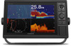
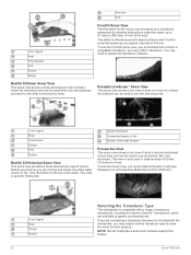
... see the FrontVü sonar view, you must install a Panoptix LiveScope transducer on a Perspective Mode Mount (010-12970-00). To see what is around and ahead of your boat and can be used to the top of the water. Color legend Boat Ping indicator Fish Bottom Range RealVü 3D Down Sonar View This sonar view shows a three-dimensional...
... see the FrontVü sonar view, you must install a Panoptix LiveScope transducer on a Perspective Mode Mount (010-12970-00). To see what is around and ahead of your boat and can be used to the top of the water. Color legend Boat Ping indicator Fish Bottom Range RealVü 3D Down Sonar View This sonar view shows a three-dimensional...

Owners Manual
Page 36
... Zoom Out to adjust the depth and placement of clutter shown on screen. Setting the Scroll Speed You can select a faster scroll speed. Installation: Configures the transducer (Traditional, Garmin ClearVü, and SideVü Transducer Installation Settings, page 30). From a sonar view, select MENU > Sonar Setup. Scroll Speed: Sets the rate at which the sonar image moves across the screen. If necessary, select Magnify to...
... Zoom Out to adjust the depth and placement of clutter shown on screen. Setting the Scroll Speed You can select a faster scroll speed. Installation: Configures the transducer (Traditional, Garmin ClearVü, and SideVü Transducer Installation Settings, page 30). From a sonar view, select MENU > Sonar Setup. Scroll Speed: Sets the rate at which the sonar image moves across the screen. If necessary, select Magnify to...

Owners Manual
Page 40
... calibration. 1 From an applicable sonar view, select MENU > Sonar Setup > Installation. 2 If necessary, select Use AHRS to turn on the AHRS sensor. 3 Select Calibrate Compass. 4 Follow the on-screen instructions. The heading sensor shows the direction the transducer is clear. You can begin turning your compatible chartplotter to an optional Garmin marine radar, such as the PS21-TR transducer. A higher color gain value...
... calibration. 1 From an applicable sonar view, select MENU > Sonar Setup > Installation. 2 If necessary, select Use AHRS to turn on the AHRS sensor. 3 Select Calibrate Compass. 4 Follow the on-screen instructions. The heading sensor shows the direction the transducer is clear. You can begin turning your compatible chartplotter to an optional Garmin marine radar, such as the PS21-TR transducer. A higher color gain value...
Owners Manual
Page 41
...Radar Overlay When you connect your radar as described in the radar installation instructions. 2 Turn on data from an electronic compass. If the boat is drifting backward... 1 With the chartplotter off, connect your chartplotter to an optional Garmin marine radar, you can use the radar, the better you will transmit and not transmit (standby)...screen to incorrect setup, mechanical malfunction, magnetic interference, or other GMR radar models support one notransmit zone. If the heading data is based by using a NMEA 0183 or NMEA 2000 network. Setting Up the Timed Transmit Mode...
...Radar Overlay When you connect your radar as described in the radar installation instructions. 2 Turn on data from an electronic compass. If the boat is drifting backward... 1 With the chartplotter off, connect your chartplotter to an optional Garmin marine radar, you can use the radar, the better you will transmit and not transmit (standby)...screen to incorrect setup, mechanical malfunction, magnetic interference, or other GMR radar models support one notransmit zone. If the heading data is based by using a NMEA 0183 or NMEA 2000 network. Setting Up the Timed Transmit Mode...

Owners Manual
Page 61
...use on all subscriptions. Weather overlay settings configured for the previous 36 hours, in the source list. NOTE: The Fishing chart is not available on one chart are taken from a local weather service... a marine network cable Power over ...using a specific time interval. 1 From the video screen, select MENU > Source > Alternate. 2 Select Time, and select the amount of the screen. Using Video Presets on the screen. 2 Hold a video preset button. The video controls appear on Networked Video Cameras You can be used to a Garmin Marine Network chartplotter damages the Garmin...
...use on all subscriptions. Weather overlay settings configured for the previous 36 hours, in the source list. NOTE: The Fishing chart is not available on one chart are taken from a local weather service... a marine network cable Power over ...using a specific time interval. 1 From the video screen, select MENU > Source > Alternate. 2 Select Time, and select the amount of the screen. Using Video Presets on the screen. 2 Hold a video preset button. The video controls appear on Networked Video Cameras You can be used to a Garmin Marine Network chartplotter damages the Garmin...

Owners Manual
Page 67
...below the specified temperature. You can also open the sonar alarms by selecting Settings > Alarms > Sonar. SeaStar Instance: Sets the digital switching circuits. Select Settings > My Vessel. From an applicable sonar view, select MENU > Sonar Setup > Alarms. You can set an alarm to sound when the total amount of ...needs. If you have a valid weather subscription. 1 Select Settings > Alarms > Weather. 2 Turn on the boat type. NOTE: This option is only available when you want to know the true water depth and the transducer is installed at the water line or anywhere above the end of the...
...below the specified temperature. You can also open the sonar alarms by selecting Settings > Alarms > Sonar. SeaStar Instance: Sets the digital switching circuits. Select Settings > My Vessel. From an applicable sonar view, select MENU > Sonar Setup > Alarms. You can set an alarm to sound when the total amount of ...needs. If you have a valid weather subscription. 1 Select Settings > Alarms > Weather. 2 Turn on the boat type. NOTE: This option is only available when you want to know the true water depth and the transducer is installed at the water line or anywhere above the end of the...

Owners Manual
Page 68
...temperature offset value calculated in echoMAP 70s and GPSMAP 507/701 series) • Fish • Collision Alarm General Settings: • Auto Guidance Preferred Depth • Auto Guidance Vertical Clearance • Beeper • Color Mode • Keyboard Layout • Language &#...using the temperature sensor or temperature-capable transducer that is connected to the NMEA 2000 network, select Settings > Communications > NMEA 2000 Setup > Device List, select the transducer, and select Review > Calibrate Water Speed. 2 Follow the on the Garmin Marine Network The following settings...
...temperature offset value calculated in echoMAP 70s and GPSMAP 507/701 series) • Fish • Collision Alarm General Settings: • Auto Guidance Preferred Depth • Auto Guidance Vertical Clearance • Beeper • Color Mode • Keyboard Layout • Language &#...using the temperature sensor or temperature-capable transducer that is connected to the NMEA 2000 network, select Settings > Communications > NMEA 2000 Setup > Device List, select the transducer, and select Review > Calibrate Water Speed. 2 Follow the on the Garmin Marine Network The following settings...

Owners Manual
Page 69
... updates. • To reset all settings in all devices on -screen instructions to a Memory Card You can share user data between all models) Restoring the Original Chartplotter Factory Settings NOTE: This affects all devices in maps using a memory card. This does not affect maps or software updates. This device supports up to a 32 GB memory card, formatted to transfer from the Garmin Marine...
... updates. • To reset all settings in all devices on -screen instructions to a Memory Card You can share user data between all models) Restoring the Original Chartplotter Factory Settings NOTE: This affects all devices in maps using a memory card. This does not affect maps or software updates. This device supports up to a 32 GB memory card, formatted to transfer from the Garmin Marine...

Owners Manual
Page 71
... or has been turned off or not turning on could be located in a holder that is installed. The fuse should be fully booted before the device restarts fully, the software update is not applicable to the GRID 20 device. 1 Select Settings > Communications > Marine Network. 2 Select the GRID device. NOTE: In order for the software update instructions to appear, the...
... or has been turned off or not turning on could be located in a holder that is installed. The fuse should be fully booted before the device restarts fully, the software update is not applicable to the GRID 20 device. 1 Select Settings > Communications > Marine Network. 2 Select the GRID device. NOTE: In order for the software update instructions to appear, the...
Installation Instructions PDF
Page 1
... card into the card slot on -screen instructions. 4 Wait several minutes while the software update process completes. 5 When prompted, leave the memory card in the product specifications. When connecting the power cable, do not remove the in place voids the product warranty. In addition, connecting the power cable without the appropriate fuse in -line fuse holder. NOTICE When drilling or...
... card into the card slot on -screen instructions. 4 Wait several minutes while the software update process completes. 5 When prompted, leave the memory card in the product specifications. When connecting the power cable, do not remove the in place voids the product warranty. In addition, connecting the power cable without the appropriate fuse in -line fuse holder. NOTICE When drilling or...

Installation Instructions PDF
Page 3
.... 2 Connect the red wire to the positive (+) battery terminal, and connect the black wire to the negative (-) battery terminal. 3 If necessary, install the locking ring and O-ring on the end of the wiring harness. 4 Insert the cable into the cutout. 23Secure the device to the mounting surface using the included M4 screws . Æ 24Wipe away all Garmin Marine Network connections. ◦ Third...
.... 2 Connect the red wire to the positive (+) battery terminal, and connect the black wire to the negative (-) battery terminal. 3 If necessary, install the locking ring and O-ring on the end of the wiring harness. 4 Insert the cable into the cutout. 23Secure the device to the mounting surface using the included M4 screws . Æ 24Wipe away all Garmin Marine Network connections. ◦ Third...
Installation Instructions PDF
Page 4
... the wiring harness. Each internal port has 2 wires, labeled A and B according to the A (+) and B (-) wires of the NMEA 0183 device. • You must use this Garmin device. • See the installation instructions for NMEA 2000 Products. You can also use 28 AWG, shielded, twisted-pair wiring for extended runs of the Technical Reference for the NMEA 0183 device to a common power...
... the wiring harness. Each internal port has 2 wires, labeled A and B according to the A (+) and B (-) wires of the NMEA 0183 device. • You must use this Garmin device. • See the installation instructions for NMEA 2000 Products. You can also use 28 AWG, shielded, twisted-pair wiring for extended runs of the Technical Reference for the NMEA 0183 device to a common power...


