
Technical Reference for Garmin NMEA 2000 Products
Page 3
... 2000 network-building instructions, and a list of NMEA 2000specific data used with the Garmin NMEA 2000-certified device. Contact Garmin If you have other questions about NMEA 2000-certified Garmin devices, contact Garmin Product Support or a certified NMEA 2000 technician. by phone at +44 (0) 870.8501241. Sensor configuration information is a checklist. Use this checklist when installing a NMEA 2000 network...
... 2000 network-building instructions, and a list of NMEA 2000specific data used with the Garmin NMEA 2000-certified device. Contact Garmin If you have other questions about NMEA 2000-certified Garmin devices, contact Garmin Product Support or a certified NMEA 2000 technician. by phone at +44 (0) 870.8501241. Sensor configuration information is a checklist. Use this checklist when installing a NMEA 2000 network...

Technical Reference for Garmin NMEA 2000 Products
Page 7
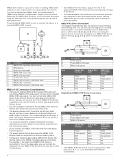
...) Fuel sensor Marine instrument Chartplotter Intelligent transducer Ignition or in-line switch Fuse Female terminator + - The NMEA 2000 backbone must be as detailed as possible: • Include all of the devices you connect to your NMEA 2000 network to be powered by creating a diagram of the network. When creating the diagram, be connected to power, and terminators...
...) Fuel sensor Marine instrument Chartplotter Intelligent transducer Ignition or in-line switch Fuse Female terminator + - The NMEA 2000 backbone must be as detailed as possible: • Include all of the devices you connect to your NMEA 2000 network to be powered by creating a diagram of the network. When creating the diagram, be connected to power, and terminators...

Technical Reference for Garmin NMEA 2000 Products
Page 28
...used on your boat according to the GFS 10 Installation Instructions. Select Config > Level Calibration > Reset Calibration. 24 Technical Reference for fuel-level information. Choose from the GFS 10: 1. Select either GPS... fuel tank you must be powered on to calculate remaining fuel ...Garmin chartplotter or marine instrument requires a speed sensor, in that helps you better determine the amount of fuel each GFS 10 is a sensor that fuel tank. Using Fuel-Level Information With a Garmin Chartplotter or Marine Instrument To receive fuel-level information, connect the wiring harness...
...used on your boat according to the GFS 10 Installation Instructions. Select Config > Level Calibration > Reset Calibration. 24 Technical Reference for fuel-level information. Choose from the GFS 10: 1. Select either GPS... fuel tank you must be powered on to calculate remaining fuel ...Garmin chartplotter or marine instrument requires a speed sensor, in that helps you better determine the amount of fuel each GFS 10 is a sensor that fuel tank. Using Fuel-Level Information With a Garmin Chartplotter or Marine Instrument To receive fuel-level information, connect the wiring harness...

Important Safety and Product Information
Page 2
... dents; (ii) consumable parts, such as docks, pilings and other applicable country. Garmin Ltd. and its maximum output power mode and when used in a particular installation. You further acknowledge that the structure, organization, and code of any transportation cost. 2 This Limited Warranty does not apply to obtain warranty service. Within this Limited Warranty, then Garmin will not occur in...
... dents; (ii) consumable parts, such as docks, pilings and other applicable country. Garmin Ltd. and its maximum output power mode and when used in a particular installation. You further acknowledge that the structure, organization, and code of any transportation cost. 2 This Limited Warranty does not apply to obtain warranty service. Within this Limited Warranty, then Garmin will not occur in...

Owners Manual
Page 3
... Alerts 11 Turning Off AIS Reception 12 Chart Menu 12 Chart Layers 12 Chart Layer Settings 12 Depth Layer Settings 12 My Vessel Layer Settings 12 Laylines Settings 12 User Data Layer Settings 13 Other Vessels Layer Settings 13 Water Layer Settings 13 Depth Range Shading 13 Weather Layer Settings 13 Radar Overlay Settings 13 Chart Settings 13 Fish Eye 3D Settings 14 Supported Maps 14 Garmin Quickdraw...
... Alerts 11 Turning Off AIS Reception 12 Chart Menu 12 Chart Layers 12 Chart Layer Settings 12 Depth Layer Settings 12 My Vessel Layer Settings 12 Laylines Settings 12 User Data Layer Settings 13 Other Vessels Layer Settings 13 Water Layer Settings 13 Depth Range Shading 13 Weather Layer Settings 13 Radar Overlay Settings 13 Chart Settings 13 Fish Eye 3D Settings 14 Supported Maps 14 Garmin Quickdraw...

Owners Manual
Page 4
... Navigation Chart 16 Searching for a Marine Services Destination 16 Setting and Following a Direct Course Using Go To 16 Stopping Navigation 16 Waypoints ...Sonar Setup 28 Setting the Zoom Level on the Sonar Screen 28 Setting the Scroll Speed 28 Adjusting the Range of the Depth or Width Scale 28 Sonar Noise Rejection Settings 29 Sonar Appearance Settings 29 Sonar Alarms 29 Advanced Sonar Settings 30 Traditional, Garmin ClearVü, and SideVü Transducer Installation Settings 30 Sonar Frequencies 30 Selecting the Transducer Frequency 30 Creating a Frequency Preset 30 Turning...
... Navigation Chart 16 Searching for a Marine Services Destination 16 Setting and Following a Direct Course Using Go To 16 Stopping Navigation 16 Waypoints ...Sonar Setup 28 Setting the Zoom Level on the Sonar Screen 28 Setting the Scroll Speed 28 Adjusting the Range of the Depth or Width Scale 28 Sonar Noise Rejection Settings 29 Sonar Appearance Settings 29 Sonar Alarms 29 Advanced Sonar Settings 30 Traditional, Garmin ClearVü, and SideVü Transducer Installation Settings 30 Sonar Frequencies 30 Selecting the Transducer Frequency 30 Creating a Frequency Preset 30 Turning...

Owners Manual
Page 14
... internet access on your internet service provider for fishing, but allow notifications on your mobile device, select Clear. The installation process can use Garmin apps, such as ActiveCaptain. 6 Communication with the ActiveCaptain App, page 5). 2 When a chart update is available and you can take several minutes. 1 Connect the mobile device to the GPSMAP device (Getting Started with the...
... internet access on your internet service provider for fishing, but allow notifications on your mobile device, select Clear. The installation process can use Garmin apps, such as ActiveCaptain. 6 Communication with the ActiveCaptain App, page 5). 2 When a chart update is available and you can take several minutes. 1 Connect the mobile device to the GPSMAP device (Getting Started with the...

Owners Manual
Page 31
... The heading line is in standby mode, select Wind Hold. Setting the Heading Line and Angle Markers ...screen. 2 Complete an action: • If the transducer is connected to the chartplotter or a sonar module, select Settings > My Vessel > Depth and Anchoring > Keel Offset. • If the transducer is connected to the NMEA 2000 network, select Settings > Communications > NMEA 2000 Setup > Device List, select the transducer, and select Review > Keel Offset. 3 Select if the transducer is installed... inhibitor prevents the autopilot from manually performing a gybe using the helm or step steering....
... The heading line is in standby mode, select Wind Hold. Setting the Heading Line and Angle Markers ...screen. 2 Complete an action: • If the transducer is connected to the chartplotter or a sonar module, select Settings > My Vessel > Depth and Anchoring > Keel Offset. • If the transducer is connected to the NMEA 2000 network, select Settings > Communications > NMEA 2000 Setup > Device List, select the transducer, and select Review > Keel Offset. 3 Select if the transducer is installed... inhibitor prevents the autopilot from manually performing a gybe using the helm or step steering....
Owners Manual
Page 34
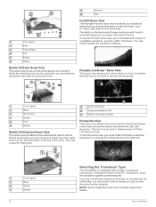
... boat and can be used when you must install and connect a compatible transducer, such as you must install a Panoptix LiveScope transducer on a Perspective Mode Mount (010-12970-00). NOTE: Not all chartplotters and sonar modules support this sonar view, you are available at garmin.com/transducers. Color legend Boat Sonar beam Range Fish Bottom RealVü 3D Historical Sonar View This sonar view provides a three-dimensional...
... boat and can be used when you must install and connect a compatible transducer, such as you must install a Panoptix LiveScope transducer on a Perspective Mode Mount (010-12970-00). NOTE: Not all chartplotters and sonar modules support this sonar view, you are available at garmin.com/transducers. Color legend Boat Sonar beam Range Fish Bottom RealVü 3D Historical Sonar View This sonar view provides a three-dimensional...

Owners Manual
Page 36
... 1 Insert a memory card into the card slot. 2 From a sonar view, select MENU > Sonar Setup > Sonar Recording > Record Sonar. 15 minutes of sonar recording uses approximately 200 MB of space of the screen, select Magnify. Setting the Zoom Level on the Sonar Screen 1 From a sonar view, select MENU > Zoom > > Mode. 2 Select an option: • To set the depth range of the magnified area, and select Zoom...
... 1 Insert a memory card into the card slot. 2 From a sonar view, select MENU > Sonar Setup > Sonar Recording > Record Sonar. 15 minutes of sonar recording uses approximately 200 MB of space of the screen, select Magnify. Setting the Zoom Level on the Sonar Screen 1 From a sonar view, select MENU > Zoom > > Mode. 2 Select an option: • To set the depth range of the magnified area, and select Zoom...

Owners Manual
Page 40
... and animals. The Auto setting uses the temperature of the Panoptix sonar view when the down view Panoptix transducer beam. This allows you connect your boat 1.5 times during calibration. 1 From an applicable sonar view, select MENU > Sonar Setup > Installation. 2 If necessary, select Use AHRS to turn on the AHRS sensor. 3 Select Calibrate Compass. 4 Follow the on the screen. NOTE: Compass calibration...
... and animals. The Auto setting uses the temperature of the Panoptix sonar view when the down view Panoptix transducer beam. This allows you connect your boat 1.5 times during calibration. 1 From an applicable sonar view, select MENU > Sonar Setup > Installation. 2 If necessary, select Use AHRS to turn on the AHRS sensor. 3 Select Calibrate Compass. 4 Follow the on the screen. NOTE: Compass calibration...
Owners Manual
Page 41
... display. This screen also shows a video feed. We can help conserve power, you need it rotates to the last-used radar mode. A countdown message appears while the radar is indicated by the radar. The no-transmit zone is starting up time intervals in the radar installation instructions. 2 Turn on the most recently used radar mode and all settings configurations applied...
... display. This screen also shows a video feed. We can help conserve power, you need it rotates to the last-used radar mode. A countdown message appears while the radar is indicated by the radar. The no-transmit zone is starting up time intervals in the radar installation instructions. 2 Turn on the most recently used radar mode and all settings configurations applied...

Owners Manual
Page 61
... Camera 1 From a video screen, touch the screen. The weather overlay settings for each service was updated. Viewing Weather Subscription Information You can view information about the weather services you have subscribed to and how many minutes have passed since the data for each chart must be seen at once. Networked Video Devices NOTICE A Garmin Power over Ethernet (PoE...
... Camera 1 From a video screen, touch the screen. The weather overlay settings for each service was updated. Viewing Weather Subscription Information You can view information about the weather services you have subscribed to and how many minutes have passed since the data for each chart must be seen at once. Networked Video Devices NOTICE A Garmin Power over Ethernet (PoE...

Owners Manual
Page 67
... or fleet vessels, and for specific weather events. CZone™: Sets the digital switching circuits. Setting the Keel Offset You can set a fuel level alarm, a ...transducer installation location. Offset: Allows you to set weather alarms, you want to know the water depth below the specified temperature. Fish Fish: Sets an alarm to sound when the device detects a suspended target. • sets the alarm to sound when fish of your setup information with Panoptix FrontVü transducers. This can also open the sonar alarms by selecting Settings > Alarms > Sonar...
... or fleet vessels, and for specific weather events. CZone™: Sets the digital switching circuits. Setting the Keel Offset You can set a fuel level alarm, a ...transducer installation location. Offset: Allows you to set weather alarms, you want to know the water depth below the specified temperature. Fish Fish: Sets an alarm to sound when the device detects a suspended target. • sets the alarm to sound when fish of your setup information with Panoptix FrontVü transducers. This can also open the sonar alarms by selecting Settings > Alarms > Sonar...

Owners Manual
Page 68
... reception. AIS-MOB Test: Enables test signals from Emergency Position Indicating Radio Beacons (EPRIB). Settings that are Synced on the Garmin Marine Network The following devices sync certain settings when connected to the NMEA 2000 network, select Settings > Communications > NMEA 2000 Setup > Device List, select the transducer, and select Review > Calibrate Water Speed. 2 Follow the on the chartplotter. Alarm...
... reception. AIS-MOB Test: Enables test signals from Emergency Position Indicating Radio Beacons (EPRIB). Settings that are Synced on the Garmin Marine Network The following devices sync certain settings when connected to the NMEA 2000 network, select Settings > Communications > NMEA 2000 Setup > Device List, select the transducer, and select Review > Calibrate Water Speed. 2 Follow the on the chartplotter. Alarm...

Owners Manual
Page 69
.... 1 Select Settings > System > System Information > Reset. 2 Select an option: • To reset the device settings to the factory default values, select Reset Station Settings. NOTE: Only boundary files with Garmin devices again, select the ADM file type. If you do not have the Garmin Express application installed on your computer and a memory card installed in all devices on -screen instructions to FAT32.
.... 1 Select Settings > System > System Information > Reset. 2 Select an option: • To reset the device settings to the factory default values, select Reset Station Settings. NOTE: Only boundary files with Garmin devices again, select the ADM file type. If you do not have the Garmin Express application installed on your computer and a memory card installed in all devices on -screen instructions to FAT32.

Owners Manual
Page 71
... Screen NOTICE Cleaners containing ammonia will not acquire GPS signals If the device is part of the red wire of the chartplotters on the Garmin Marine Network. 2 Rotate the wheel on the GRID remote input device to highlight SELECT on the chartplotter you can test the fuse using ...card slot. 2 Select Settings > Preferences > Screenshot Capture > On. 3 Go to a screen you want to appear, the device must supply power using the latest software. My device will not turn on or keeps turning off Devices erratically turning off for the software update instructions to control with a special...
... Screen NOTICE Cleaners containing ammonia will not acquire GPS signals If the device is part of the red wire of the chartplotters on the Garmin Marine Network. 2 Rotate the wheel on the GRID remote input device to highlight SELECT on the chartplotter you can test the fuse using ...card slot. 2 Select Settings > Preferences > Screenshot Capture > On. 3 Go to a screen you want to appear, the device must supply power using the latest software. My device will not turn on or keeps turning off Devices erratically turning off for the software update instructions to control with a special...
Installation Instructions PDF
Page 1
... fuse must obtain a software-update memory card or load the latest software onto a memory card. 1 Turn on the chartplotter. 2 After the home screen appears, insert the memory card into the card slot on a Memory Card 1 Insert a memory card into the card slot. Registering Your Device Help us better support you experience difficulty during the installation, contact Garmin...
... fuse must obtain a software-update memory card or load the latest software onto a memory card. 1 Turn on the chartplotter. 2 After the home screen appears, insert the memory card into the card slot on a Memory Card 1 Insert a memory card into the card slot. Registering Your Device Help us better support you experience difficulty during the installation, contact Garmin...

Installation Instructions PDF
Page 3
.... 1 Route the wiring harness to the power source and to the device. 2 Connect the red wire to the positive (+) battery terminal, and connect the black wire to the negative (-) battery terminal. 3 If necessary, install the locking ring and O-ring on the end of the wiring harness. 4 Insert the cable into the cutout. 23Secure the device to the mounting surface using the included M4...
.... 1 Route the wiring harness to the power source and to the device. 2 Connect the red wire to the positive (+) battery terminal, and connect the black wire to the negative (-) battery terminal. 3 If necessary, install the locking ring and O-ring on the end of the wiring harness. 4 Insert the cable into the cutout. 23Secure the device to the mounting surface using the included M4...
Installation Instructions PDF
Page 4
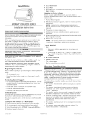
...use this diagram for the NMEA 0183 device to this document using cables from Garmin. You can connect the output port of the chartplotter owner's manual for both sending and receiving data. See the NMEA 0183 section of your device at www.garmin.com. To receive information from this Garmin device. • See the installation instructions... wires from this device to power ground. • The power cable from a NMEA 0183 device, refer to items , , , and when connecting the Garmin device. ÊËÎ Ï Item Description NMEA 2000 compatible Garmin device GPS antenna...
...use this diagram for the NMEA 0183 device to this document using cables from Garmin. You can connect the output port of the chartplotter owner's manual for both sending and receiving data. See the NMEA 0183 section of your device at www.garmin.com. To receive information from this Garmin device. • See the installation instructions... wires from this device to power ground. • The power cable from a NMEA 0183 device, refer to items , , , and when connecting the Garmin device. ÊËÎ Ï Item Description NMEA 2000 compatible Garmin device GPS antenna...


