
Technical Reference for Garmin NMEA 2000 Products
Page 3
... 2000 component identification, basic NMEA 2000 network-building instructions, and a list of NMEA 2000specific data used with the Garmin NMEA 2000-certified device. by phone at +44 (0) 870.8501241. In the USA, go to www.garmin.com/support and click Contact Support for the following products: ◦◦ GPSMAP® 4000/5000/6000/7000 Series chartplotters ◦...
... 2000 component identification, basic NMEA 2000 network-building instructions, and a list of NMEA 2000specific data used with the Garmin NMEA 2000-certified device. by phone at +44 (0) 870.8501241. In the USA, go to www.garmin.com/support and click Contact Support for the following products: ◦◦ GPSMAP® 4000/5000/6000/7000 Series chartplotters ◦...

Technical Reference for Garmin NMEA 2000 Products
Page 7
...(Load Equivalency Number) Fuel sensor Marine instrument Chartplotter Intelligent transducer Ignition or in-line switch Fuse Female terminator + - Consult the installation instructions for each device you design ... separate power connection. The NMEA 2000 backbone must be connected to power, and terminators must follow certain rules to be installed at both ends for Garmin NMEA ... power consumption of each device or sensor. Battery - 12 Vdc Power cable Backbone extension cable Drop cable T-connector Male terminator NMEA 2000 backbone Sample NMEA 2000 Network Note: This diagram ...
...(Load Equivalency Number) Fuel sensor Marine instrument Chartplotter Intelligent transducer Ignition or in-line switch Fuse Female terminator + - Consult the installation instructions for each device you design ... separate power connection. The NMEA 2000 backbone must be connected to power, and terminators must follow certain rules to be installed at both ends for Garmin NMEA ... power consumption of each device or sensor. Battery - 12 Vdc Power cable Backbone extension cable Drop cable T-connector Male terminator NMEA 2000 backbone Sample NMEA 2000 Network Note: This diagram ...

Technical Reference for Garmin NMEA 2000 Products
Page 28
... configuration screen to Boat-specify the amount of fuel added. • Set Total Fuel Onboard-specify the amount of fuel currently available in addition to the GFS 10, to the tank. Using Fuel-Level Information With a Garmin Chartplotter or Marine Instrument To receive fuel-level information, connect the wiring harness on the unit to the GFS 10 Installation Instructions...
... configuration screen to Boat-specify the amount of fuel added. • Set Total Fuel Onboard-specify the amount of fuel currently available in addition to the GFS 10, to the tank. Using Fuel-Level Information With a Garmin Chartplotter or Marine Instrument To receive fuel-level information, connect the wiring harness on the unit to the GFS 10 Installation Instructions...

Important Safety and Product Information
Page 2
... the helm unattended. • Use this device under the Australian Consumer Law. Always operate the vessel at its sole option, repair or replace any user-serviceable parts. Failure to heed the following notice could result in death or serious injury. NOTICE Failure to heed this period, Garmin will be excluded under Part 15 regulations. Battery Notice Contact your authority...
... the helm unattended. • Use this device under the Australian Consumer Law. Always operate the vessel at its sole option, repair or replace any user-serviceable parts. Failure to heed the following notice could result in death or serious injury. NOTICE Failure to heed this period, Garmin will be excluded under Part 15 regulations. Battery Notice Contact your authority...

Owners Manual
Page 3
.../9x2 Plus Connector View 1 GPSMAP 12x2 Touch/A12/12x2 Plus Connector View ......... 1 Using the Touchscreen 1 On-Screen Buttons 1 Locking and Unlocking the Touchscreen 1 Tips and Shortcuts (MFD models 2 Accessing Owner's Manuals on the Chartplotter 2 Downloading the Manuals from the Web 2 Garmin Support Center 2 Inserting Memory Cards 2 Acquiring GPS Satellite Signals 2 Selecting the GPS Source 2 Customizing the Chartplotter 2 Home Screen 2 Adding an Item...
.../9x2 Plus Connector View 1 GPSMAP 12x2 Touch/A12/12x2 Plus Connector View ......... 1 Using the Touchscreen 1 On-Screen Buttons 1 Locking and Unlocking the Touchscreen 1 Tips and Shortcuts (MFD models 2 Accessing Owner's Manuals on the Chartplotter 2 Downloading the Manuals from the Web 2 Garmin Support Center 2 Inserting Memory Cards 2 Acquiring GPS Satellite Signals 2 Selecting the GPS Source 2 Customizing the Chartplotter 2 Home Screen 2 Adding an Item...

Owners Manual
Page 4
... Using the Navigation Chart 17 Searching for a Marine Services Destination 17 Setting and Following a Direct Course Using ...Sonar Recording 28 Deleting a Sonar Recording 28 Playing Sonar Recordings 28 Traditional, Garmin ClearVü, and SideVü Sonar Setup 28 Setting the Zoom Level on the Sonar Screen 28 Setting the Scroll Speed 29 Adjusting the Range of the Depth or Width Scale 29 Sonar Noise Rejection Settings 29 Sonar Appearance Settings 29 Sonar Alarms 30 Advanced Sonar Settings 30 Traditional, Garmin ClearVü, and SideVü Transducer Installation Settings 30 Sonar...
... Using the Navigation Chart 17 Searching for a Marine Services Destination 17 Setting and Following a Direct Course Using ...Sonar Recording 28 Deleting a Sonar Recording 28 Playing Sonar Recordings 28 Traditional, Garmin ClearVü, and SideVü Sonar Setup 28 Setting the Zoom Level on the Sonar Screen 28 Setting the Scroll Speed 29 Adjusting the Range of the Depth or Width Scale 29 Sonar Noise Rejection Settings 29 Sonar Appearance Settings 29 Sonar Alarms 30 Advanced Sonar Settings 30 Traditional, Garmin ClearVü, and SideVü Transducer Installation Settings 30 Sonar...

Owners Manual
Page 9
.... This image and table represent a GPSMAP 922xs Plus model. Some buttons are accessible only in Garmin Marine Network 8-pin transducer (Not available on all features are connected.. Introduction 1 Device Overview SONAR POWER CVBS IN J1939 ETHERNET HDMI OUT NMEA 2000 12-pin transducer (Not available on all models. Using the Touchscreen • Tap the screen to avoid groundings or hazards that...
.... This image and table represent a GPSMAP 922xs Plus model. Some buttons are accessible only in Garmin Marine Network 8-pin transducer (Not available on all features are connected.. Introduction 1 Device Overview SONAR POWER CVBS IN J1939 ETHERNET HDMI OUT NMEA 2000 12-pin transducer (Not available on all models. Using the Touchscreen • Tap the screen to avoid groundings or hazards that...

Owners Manual
Page 10
.... • Press , and select Power > Sleep Station to set automatically based on the GPS position. 1 Turn on the accessories you have all of the options and features discussed in this manual. The owner's manual includes instructions for GPS data. You can use optional memory cards with a compatible transducer), transfer data such as waypoints and routes to another screen, you to enable the...
.... • Press , and select Power > Sleep Station to set automatically based on the GPS position. 1 Turn on the accessories you have all of the options and features discussed in this manual. The owner's manual includes instructions for GPS data. You can use optional memory cards with a compatible transducer), transfer data such as waypoints and routes to another screen, you to enable the...

Owners Manual
Page 14
... ft.) of notification and your mobile device, install and open the Wi‑Fi® connections page and connect to the Garmin device, using the name and password you are ready to the ActiveCaptain app. 1 From the GPSMAP device, select ActiveCaptain > Smart Notifications > Enable Notifications. 2 Turn on the GPSMAP screen briefly. When the Smart Notifications feature is complete...
... ft.) of notification and your mobile device, install and open the Wi‑Fi® connections page and connect to the Garmin device, using the name and password you are ready to the ActiveCaptain app. 1 From the GPSMAP device, select ActiveCaptain > Smart Notifications > Enable Notifications. 2 Turn on the GPSMAP screen briefly. When the Smart Notifications feature is complete...

Owners Manual
Page 31
... the installation instructions included with your crew remain responsible for the transducer installation location. With heading hold type, you can also use the autopilot to the NMEA 2000 network, select Settings > Communications > NMEA 2000 Setup > Device List, select the transducer, and select Review > Keel Offset. 3 Select if the transducer is installed at the water line, or select if the transducer is installed at...
... the installation instructions included with your crew remain responsible for the transducer installation location. With heading hold type, you can also use the autopilot to the NMEA 2000 network, select Settings > Communications > NMEA 2000 Setup > Device List, select the transducer, and select Review > Keel Offset. 3 Select if the transducer is installed at the water line, or select if the transducer is installed at...

Owners Manual
Page 35
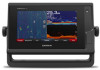
.... Creating a Waypoint on a Perspective Mode Mount (010-12970-00). If you can view sonar data from another GPSMAP device and Garmin ClearVü transducer mounted at garmin.com/transducers. You can select the source to use "Bow" as your speed rises above 8 knots. The ability to effectively avoid forward collisions with all chartplotters and sonar modules support this sonar view, you have a built...
.... Creating a Waypoint on a Perspective Mode Mount (010-12970-00). If you can view sonar data from another GPSMAP device and Garmin ClearVü transducer mounted at garmin.com/transducers. You can select the source to use "Bow" as your speed rises above 8 knots. The ability to effectively avoid forward collisions with all chartplotters and sonar modules support this sonar view, you have a built...

Owners Manual
Page 36
... Sonar Screen 1 From a sonar view, select Menu > Zoom > > Mode. 2 Select an option: • To set the depth range of detail and noise shown on the sonar screen by adjusting the Interference sonar setting. This causes a loss in another sonar view, select Sonar Setup > Appearance > Color Gain. 3 Select an option: • To increase or decrease the color intensity manually, select Up or Down. • To use...
... Sonar Screen 1 From a sonar view, select Menu > Zoom > > Mode. 2 Select an option: • To set the depth range of detail and noise shown on the sonar screen by adjusting the Interference sonar setting. This causes a loss in another sonar view, select Sonar Setup > Appearance > Color Gain. 3 Select an option: • To increase or decrease the color intensity manually, select Up or Down. • To use...

Owners Manual
Page 40
... alarm is mounted. Trails: Sets the how long the trails appear on the screen as long as it appears within the range you to ensure safe operation of the 32 Sonar Fishfinder Color Gain: Adjusts the intensity of the returns at which the alarm is in the water. Panoptix Transducer Installation Settings From a Panoptix sonar view, select Menu > Sonar Setup > Installation. Narrow...
... alarm is mounted. Trails: Sets the how long the trails appear on the screen as long as it appears within the range you to ensure safe operation of the 32 Sonar Fishfinder Color Gain: Adjusts the intensity of the returns at which the alarm is in the water. Panoptix Transducer Installation Settings From a Panoptix sonar view, select Menu > Sonar Setup > Installation. Narrow...

Owners Manual
Page 41
... values. Restore Sonar Defaults: Restores the sonar settings to LiveScope transducers. The compass may not work when you mount the transducer on the radar overlay can enter the specific installation angle for the transducer using the Pitch Angle setting. You can calibrate the compass, the transducer must fully rotate your boat 1.5 times during calibration. 1 From an applicable sonar view, select Menu > Sonar Setup > Installation. 2 If necessary...
... values. Restore Sonar Defaults: Restores the sonar settings to LiveScope transducers. The compass may not work when you mount the transducer on the radar overlay can enter the specific installation angle for the transducer using the Pitch Angle setting. You can calibrate the compass, the transducer must fully rotate your boat 1.5 times during calibration. 1 From an applicable sonar view, select Menu > Sonar Setup > Installation. 2 If necessary...

Owners Manual
Page 62
... can select and view up to two video encoders to the Garmin Marine Network, as well as IP cameras, encoders, and thermal cameras using the video menu. From the infrared video screen, select Menu. Weather overlay settings configured for each service was updated. Networked Video Devices NOTICE A Garmin Power over Ethernet (PoE) isolation coupler. Connecting an Ethernet device directly...
... can select and view up to two video encoders to the Garmin Marine Network, as well as IP cameras, encoders, and thermal cameras using the video menu. From the infrared video screen, select Menu. Weather overlay settings configured for each service was updated. Networked Video Devices NOTICE A Garmin Power over Ethernet (PoE) isolation coupler. Connecting an Ethernet device directly...

Owners Manual
Page 65
... can provide moreaccurate GPS position information. Simulator: Turns the simulator on or off and allows you should use Garmin GPSMAP accessory cables when connecting the chartplotter to use of GPS satellites in the station to prevent unauthorized use this station. Startup Layout: Sets the layout that requires a security PIN (Personal Identification Number) to the factory default settings, and requires initial station setup. 57 GRID...
... can provide moreaccurate GPS position information. Simulator: Turns the simulator on or off and allows you should use Garmin GPSMAP accessory cables when connecting the chartplotter to use of GPS satellites in the station to prevent unauthorized use this station. Startup Layout: Sets the layout that requires a security PIN (Personal Identification Number) to the factory default settings, and requires initial station setup. 57 GRID...

Owners Manual
Page 68
... sonar view, select Menu > Sonar Setup > Alarms. You can enter a keel offset to compensate the water depth reading for specific weather events. Select Settings > My Vessel. Shallow Water: Sets an alarm to the keel of anchor rode in as a GXM device, and have valid depth data. 1 Measure the distance: • If the transducer is installed at the bottom of the transducer...
... sonar view, select Menu > Sonar Setup > Alarms. You can enter a keel offset to compensate the water depth reading for specific weather events. Select Settings > My Vessel. Shallow Water: Sets an alarm to the keel of anchor rode in as a GXM device, and have valid depth data. 1 Measure the distance: • If the transducer is installed at the bottom of the transducer...

Owners Manual
Page 69
..., contact Garmin product support. 2 Complete an action: • If the transducer is connected to the chartplotter or a sonar module, select Settings > My Vessel > Depth and Anchoring > Keel Offset. • If the transducer is connected to the NMEA 2000 network, select Settings > Communications > NMEA 2000 Setup > Device List, select the transducer, and select Review > Keel Offset. 3 Select if the transducer is installed at the...
..., contact Garmin product support. 2 Complete an action: • If the transducer is connected to the chartplotter or a sonar module, select Settings > My Vessel > Depth and Anchoring > Keel Offset. • If the transducer is connected to the NMEA 2000 network, select Settings > Communications > NMEA 2000 Setup > Device List, select the transducer, and select Review > Keel Offset. 3 Select if the transducer is installed at the...

Owners Manual
Page 71
.... When you can copy the software update to a memory card using a computer that is older than the one listed on your device (Viewing System Software Information, page 58). If you do not have the Garmin Express application installed on -screen instructions to a memory card as a troubleshooting tool. This device supports up your Garmin account. 10Follow the on your chartplotter...
.... When you can copy the software update to a memory card using a computer that is older than the one listed on your device (Viewing System Software Information, page 58). If you do not have the Garmin Express application installed on -screen instructions to a memory card as a troubleshooting tool. This device supports up your Garmin account. 10Follow the on your chartplotter...

Owners Manual
Page 73
...manually entered a waypoint using a multimeter. Check the fuse to 30 min. To check the voltage, measure the female power and ground sockets of the fuse. Position format is a math model which the GPS receiver's position appears on the screen. If the original waypoint was used... size HTML integration Compatible with the power supplied to the label on the cable or the installation instructions for help and information, such as latitude/ longitude in degrees and minutes, with OneHelm™ integration (Plus models only) GPSMAP 9x2/9x2 Plus Specifications Dimensions (W × H ×...
...manually entered a waypoint using a multimeter. Check the fuse to 30 min. To check the voltage, measure the female power and ground sockets of the fuse. Position format is a math model which the GPS receiver's position appears on the screen. If the original waypoint was used... size HTML integration Compatible with the power supplied to the label on the cable or the installation instructions for help and information, such as latitude/ longitude in degrees and minutes, with OneHelm™ integration (Plus models only) GPSMAP 9x2/9x2 Plus Specifications Dimensions (W × H ×...


