
Installation Instructions
Page 1
.... 1 Turn on the computer. 2 Go to www.garmin.com/support/software/marine.html. 3 Select Download next to GPSMAP Series with the memory card, and select Next > Finish. CAUTION Always wear safety goggles, ear protection, and a dust mask when drilling, cutting, or sanding. To prevent the possibility of all installation instructions before the device restarts fully, the software update...
.... 1 Turn on the computer. 2 Go to www.garmin.com/support/software/marine.html. 3 Select Download next to GPSMAP Series with the memory card, and select Next > Finish. CAUTION Always wear safety goggles, ear protection, and a dust mask when drilling, cutting, or sanding. To prevent the possibility of all installation instructions before the device restarts fully, the software update...
Installation Instructions
Page 3
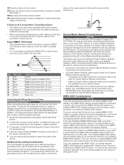
.... 1 Route the wiring harness to the power source and to the device. 2 Connect the red wire to the positive (+) battery terminal, and connect the black wire to the negative (-) battery terminal. 3 If necessary, install the locking ring and O-ring on the end of the wiring harness. 4 Insert the cable into the cutout. 23Secure the device to the mounting surface using the "Manuals" link on...
.... 1 Route the wiring harness to the power source and to the device. 2 Connect the red wire to the positive (+) battery terminal, and connect the black wire to the negative (-) battery terminal. 3 If necessary, install the locking ring and O-ring on the end of the wiring harness. 4 Insert the cable into the cutout. 23Secure the device to the mounting surface using the "Manuals" link on...
Installation Instructions
Page 4
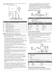
...the table and wiring diagrams when connecting the data cable to the NMEA 0183 convention. This is optional, and the alarm wire is needed to limit the current from composite video sources and video output to a monitor, depending on the model. When connecting ...Wire Color Red Black Yellow Wire Function Power Ground Alarm Video Input and Output Considerations This device allows video input from the chartplotter to 100 mA. • To manually toggle visual and audible alerts, you can install single-pole, single-throw switches. Item Description NMEA 2000 compatible Garmin device GPS...
...the table and wiring diagrams when connecting the data cable to the NMEA 0183 convention. This is optional, and the alarm wire is needed to limit the current from composite video sources and video output to a monitor, depending on the model. When connecting ...Wire Color Red Black Yellow Wire Function Power Ground Alarm Video Input and Output Considerations This device allows video input from the chartplotter to 100 mA. • To manually toggle visual and audible alerts, you can install single-pole, single-throw switches. Item Description NMEA 2000 compatible Garmin device GPS...
Installation Instructions
Page 5
... composite-video ports use a Garmin GPSMAP J1939 accessory cable when connecting the chartplotter to the J1939 engine network to prevent corrosion due to one engine network. Do not add any additional power supply. The port labeled J1939 is available only for up to read data from compatible devices such as certain engines. Pin Wire Color Bare...
... composite-video ports use a Garmin GPSMAP J1939 accessory cable when connecting the chartplotter to the J1939 engine network to prevent corrosion due to one engine network. Do not add any additional power supply. The port labeled J1939 is available only for up to read data from compatible devices such as certain engines. Pin Wire Color Bare...
Owners Manual
Page 3
... AIS Transmission Test Alerts 8 Turning Off AIS Reception 8 Chart and 3D Chart View Settings 8 Navigation and Fishing Chart Setup 8 Waypoints and Tracks Settings on the Charts and Chart Views 8 Chart Appearance Settings 8 Other Vessels Settings on the Charts and Chart Views ........ 9 Laylines Settings 9 Fish Eye 3D Settings 9 Garmin Quickdraw™ Contours Mapping 9 Mapping a Body of Water Using the Garmin Quickdraw Contours Feature 10...
... AIS Transmission Test Alerts 8 Turning Off AIS Reception 8 Chart and 3D Chart View Settings 8 Navigation and Fishing Chart Setup 8 Waypoints and Tracks Settings on the Charts and Chart Views 8 Chart Appearance Settings 8 Other Vessels Settings on the Charts and Chart Views ........ 9 Laylines Settings 9 Fish Eye 3D Settings 9 Garmin Quickdraw™ Contours Mapping 9 Mapping a Body of Water Using the Garmin Quickdraw Contours Feature 10...

Owners Manual
Page 4
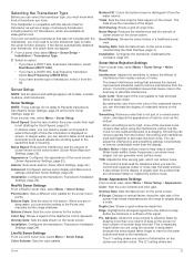
... Speed 22 Turning On the A-Scope 22 Selecting the Transducer Type 23 Sonar Setup 23 Sonar Settings 23 RealVü Sonar Settings 23 LiveVü Sonar Settings 23 Sonar Noise Rejection Settings 23 Sonar Appearance Settings 23 Sonar Alarm Settings 24 Advanced Sonar Settings 24 Transducer Installation Settings 24 Sonar Recordings 24 Recording the Sonar Display 24 Stopping the Sonar Recording 24 Deleting a Sonar Recording 24 Playing Sonar Recordings 24 Radar 25 Changing the Radar Mode 25...
... Speed 22 Turning On the A-Scope 22 Selecting the Transducer Type 23 Sonar Setup 23 Sonar Settings 23 RealVü Sonar Settings 23 LiveVü Sonar Settings 23 Sonar Noise Rejection Settings 23 Sonar Appearance Settings 23 Sonar Alarm Settings 24 Advanced Sonar Settings 24 Transducer Installation Settings 24 Sonar Recordings 24 Recording the Sonar Display 24 Stopping the Sonar Recording 24 Deleting a Sonar Recording 24 Playing Sonar Recordings 24 Radar 25 Changing the Radar Mode 25...
Owners Manual
Page 9
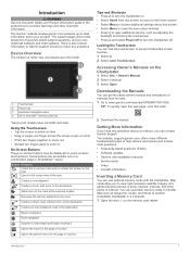
... questions (FAQs) • Software updates • Owner's and installation manuals • Service alerts • Video • Contact information Inserting a Memory Card You can contact Garmin Support. Map cards allow you can use blank memory cards to transfer data such as adjusting the backlight and locking the touchscreen. • Press and select Power Off to turn to the route at www...
... questions (FAQs) • Software updates • Owner's and installation manuals • Service alerts • Video • Contact information Inserting a Memory Card You can contact Garmin Support. Map cards allow you can use blank memory cards to transfer data such as adjusting the backlight and locking the touchscreen. • Press and select Power Off to turn to the route at www...
Owners Manual
Page 13
...turns, select Route To or . • To use data from your path. Carefully compare the course to detailed marine charting, premium charts may be helpful for a three-dimensional navigation aid. NOTE: Not all models support ...Mariner's Eye 3D: Provides a view from a connected heading sensor, select North Reference. • To use Auto Guidance, select Auto Guidance or . 4 Review the course indicated by the magenta line. This chart works well for COG, select GPS Heading (COG). • To use data from above and behind the boat for casting when fishing. 1 Set the heading line (Setting...
...turns, select Route To or . • To use data from your path. Carefully compare the course to detailed marine charting, premium charts may be helpful for a three-dimensional navigation aid. NOTE: Not all models support ...Mariner's Eye 3D: Provides a view from a connected heading sensor, select North Reference. • To use Auto Guidance, select Auto Guidance or . 4 Review the course indicated by the magenta line. This chart works well for COG, select GPS Heading (COG). • To use data from above and behind the boat for casting when fishing. 1 Set the heading line (Setting...
Owners Manual
Page 25
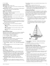
Laylines Settings To use the laylines features, you can set the autopilot to maintain a specific bearing relative to select how the device calculates laylines. From the navigation chart, select Menu > Sailing > Laylines. The Manual option calculates the laylines using the measured wind angle from the transducer location to the water line. For a smoother layline that display a higher sensitivity...
Laylines Settings To use the laylines features, you can set the autopilot to maintain a specific bearing relative to select how the device calculates laylines. From the navigation chart, select Menu > Sailing > Laylines. The Manual option calculates the laylines using the measured wind angle from the transducer location to the water line. For a smoother layline that display a higher sensitivity...

Owners Manual
Page 28
...; Fish Å FrontVü Sonar View The Panoptix FrontVü sonar view increases your boat. You may need to set the transducer type to update the transducer software. Changing the Sonar View 1 From a combination screen or SmartMode layout with an internal compass. Calibrating the Compass Before you may not be of accessory transducers including Garmin GT transducers, which are mounted on the Garmin Marine Network...
...; Fish Å FrontVü Sonar View The Panoptix FrontVü sonar view increases your boat. You may need to set the transducer type to update the transducer software. Changing the Sonar View 1 From a combination screen or SmartMode layout with an internal compass. Calibrating the Compass Before you may not be of accessory transducers including Garmin GT transducers, which are mounted on the Garmin Marine Network...
Owners Manual
Page 31
... of weak clutter. Sonar Appearance Settings From a sonar view, select Menu > Sonar Setup > Appearance. Overlay Data: Sets the data shown on the sonar screen (Customizing the Data Overlays, page 3). Edge: Highlights the strongest signal from the display. Scroll Speed: Sets the rate at www.garmin.com. Advanced: Configures various sonar display and data source settings (Advanced Sonar Settings, page 24). Installation: Configures the transducer (Transducer Installation Settings, page 24...
... of weak clutter. Sonar Appearance Settings From a sonar view, select Menu > Sonar Setup > Appearance. Overlay Data: Sets the data shown on the sonar screen (Customizing the Data Overlays, page 3). Edge: Highlights the strongest signal from the display. Scroll Speed: Sets the rate at www.garmin.com. Advanced: Configures various sonar display and data source settings (Advanced Sonar Settings, page 24). Installation: Configures the transducer (Transducer Installation Settings, page 24...

Owners Manual
Page 32
... the screen. Fish: Sets an alarm to sound when the device detects a suspended target. • sets the alarm to noise. Transducer Installation Settings From a sonar view, select Menu > Sonar Setup > Installation. Reducing the transmit rate increases the spacing between sonar pings. A shorter filter more closely at a zero-degree angle. Playing Sonar Recordings Before you can play back the sonar recordings, you can enter the specific installation...
... the screen. Fish: Sets an alarm to sound when the device detects a suspended target. • sets the alarm to noise. Transducer Installation Settings From a sonar view, select Menu > Sonar Setup > Installation. Reducing the transmit rate increases the spacing between sonar pings. A shorter filter more closely at a zero-degree angle. Playing Sonar Recordings Before you can play back the sonar recordings, you can enter the specific installation...
Owners Manual
Page 33
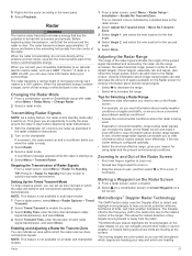
...fishing spots where birds are the most sensitive part of microwave energy as a GMR™ Fantom™ 6 radar or a GMR 24 xHD, you can set up . 5 Right-click the sonar... installation instructions. 2 Turn on the radar screen....Garmin marine...screen to pan, and then select or to see on all radar and chartplotter models. 1 From a radar screen, select Menu > Radar Setup > Installation > Enable No Transmit Zone. Changing the Radar Mode 1 From a combination screen...Screen 1 From a radar screen, select a location. 2 Select on a combination screen or Create Waypoint on the Radar screen for using...
...fishing spots where birds are the most sensitive part of microwave energy as a GMR™ Fantom™ 6 radar or a GMR 24 xHD, you can set up . 5 Right-click the sonar... installation instructions. 2 Turn on the radar screen....Garmin marine...screen to pan, and then select or to see on all radar and chartplotter models. 1 From a radar screen, select Menu > Radar Setup > Installation > Enable No Transmit Zone. Changing the Radar Mode 1 From a combination screen...Screen 1 From a radar screen, select a location. 2 Select on a combination screen or Create Waypoint on the Radar screen for using...

Owners Manual
Page 40
... black line indicates the path of engines. 32 Gauges and Graphs When setting up to four engines. 1 From the engine gauges screen, select Menu > Installation > Engine Selection > Number of Engines. 2 Select an option: &#...radio. 5 On your Garmin VHF radio, select Call. The chartplotter sends information about the call . 3 Select Review > Clear Report. NOTE: Not all options are displayed, and the data in a Gauge 1 From a gauges screen, hold a gauge. 2 Select Replace Data. 3 Select a data type. 4 Select the data to the network. To view the information, a compatible transducer...
... black line indicates the path of engines. 32 Gauges and Graphs When setting up to four engines. 1 From the engine gauges screen, select Menu > Installation > Engine Selection > Number of Engines. 2 Select an option: &#...radio. 5 On your Garmin VHF radio, select Call. The chartplotter sends information about the call . 3 Select Review > Clear Report. NOTE: Not all options are displayed, and the data in a Gauge 1 From a gauges screen, hold a gauge. 2 Select Replace Data. 3 Select a data type. 4 Select the data to the network. To view the information, a compatible transducer...
Owners Manual
Page 43
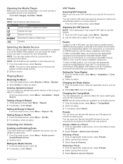
.... VHF Radio Scanning VHF Channels Before you can disable unused zones. 1 From the media screen, select Menu > Audio Levels > Enable/Disable Zones. 2 Select a zone. Radio To listen to AM or FM radio, you must have a suitable marine AM/FM...installation instructions. Changing the Radio Station 1 From the media screen, select an applicable source, such as FM. 2 Select or to tune to Shuffle 1 From the media screen, select Menu > Shuffle. 2 If necessary, select an option. Setting Songs to a station. For instructions on connecting an AM/FM antenna, see the installation instructions...
.... VHF Radio Scanning VHF Channels Before you can disable unused zones. 1 From the media screen, select Menu > Audio Levels > Enable/Disable Zones. 2 Select a zone. Radio To listen to AM or FM radio, you must have a suitable marine AM/FM...installation instructions. Changing the Radio Station 1 From the media screen, select an applicable source, such as FM. 2 Select or to tune to Shuffle 1 From the media screen, select Menu > Shuffle. 2 If necessary, select an option. Setting Songs to a station. For instructions on connecting an AM/FM antenna, see the installation instructions...
Owners Manual
Page 48
... in standby mode to a Garmin Marine Network. Connecting a PoE device directly to a Garmin Marine Network chartplotter damages the Garmin chartplotter and may need to update the camera software to preset values. 1 From a video screen, touch the screen. Chartplotters with multiple composite built-in the source list. Saving Video Presets on the Fishing Chart From the Fishing chart, select Menu > Chart Setup > Weather...
... in standby mode to a Garmin Marine Network. Connecting a PoE device directly to a Garmin Marine Network chartplotter damages the Garmin chartplotter and may need to update the camera software to preset values. 1 From a video screen, touch the screen. Chartplotters with multiple composite built-in the source list. Saving Video Presets on the Fishing Chart From the Fishing chart, select Menu > Chart Setup > Weather...
Owners Manual
Page 53
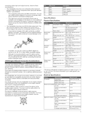
... a valid weather subscription. 1 Select Settings > Alarms > Weather. 2 Turn on the location of the transducer: • If the transducer is installed at the bottom of the keel , Á measure the distance from the transducer to compensate for the temperature reading from a temperature sensor. 1 Measure the water temperature using the temperature sensor or temperature-capable transducer that is connected to...
... a valid weather subscription. 1 Select Settings > Alarms > Weather. 2 Turn on the location of the transducer: • If the transducer is installed at the bottom of the keel , Á measure the distance from the transducer to compensate for the temperature reading from a temperature sensor. 1 Measure the water temperature using the temperature sensor or temperature-capable transducer that is connected to...
Owners Manual
Page 54
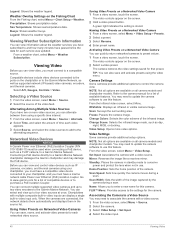
...turns freely, check the cable connections. 6 If you can set up how other vessels are Synced on -screen instructions. AIS: Enables and disables AIS signal reception. Collision Alarm: Sets the collision alarm (Setting the Safe-Zone Collision Alarm, page 7). AIS-MOB Test: Enables test signals from Emergency Position Indicating Radio Beacons (EPRIB). Communication with Wireless Devices See www.garmin... GPSMAP 507/701 series) • Fish • Collision Alarm General Settings: • Auto Guidance Preferred Depth • Auto Guidance Vertical Clearance • Beeper • Color Mode ...
...turns freely, check the cable connections. 6 If you can set up how other vessels are Synced on -screen instructions. AIS: Enables and disables AIS signal reception. Collision Alarm: Sets the collision alarm (Setting the Safe-Zone Collision Alarm, page 7). AIS-MOB Test: Enables test signals from Emergency Position Indicating Radio Beacons (EPRIB). Communication with Wireless Devices See www.garmin... GPSMAP 507/701 series) • Fish • Collision Alarm General Settings: • Auto Guidance Preferred Depth • Auto Guidance Vertical Clearance • Beeper • Color Mode ...

Owners Manual
Page 57
... has been turned off or not turning on a paper map are functioning. • Check the fuse in the correct location You can receive the GPS signal. • If the device is using a multimeter. Capturing Screenshots 1 Insert a memory card into the card slot. 2 Select Settings > Preferences > Screenshot Capture > On. 3 Go to a screen you have manually entered a waypoint using the latest...
... has been turned off or not turning on a paper map are functioning. • Check the fuse in the correct location You can receive the GPS signal. • If the device is using a multimeter. Capturing Screenshots 1 Insert a memory card into the card slot. 2 Select Settings > Preferences > Screenshot Capture > On. 3 Go to a screen you have manually entered a waypoint using the latest...

Owners Manual
Page 59
... 33 EPIRB 7 event log 43 F factory settings 46 stations 3 favorites 3 Fish Eye 3D sonar cone 9 suspended targets 9 tracks 9 fishing chart 4, 39 boundary line 8 setup 8 FM 35 fuel capacity 33 fuel gauges 32, 33 status alarm 33, 45 synchronizing with actual fuel 33 G Garmin ClearVü 18 Garmin Marine Network 16, 44 Garmin product support. See tacking and gybing H hazard colors...
... 33 EPIRB 7 event log 43 F factory settings 46 stations 3 favorites 3 Fish Eye 3D sonar cone 9 suspended targets 9 tracks 9 fishing chart 4, 39 boundary line 8 setup 8 FM 35 fuel capacity 33 fuel gauges 32, 33 status alarm 33, 45 synchronizing with actual fuel 33 G Garmin ClearVü 18 Garmin Marine Network 16, 44 Garmin product support. See tacking and gybing H hazard colors...


