
?Important Safety and Product Information
Page 2
...batteries may experience a shortened life span or may not cause interference, and (2) this equipment does cause harmful interference to radio or television reception, which source code is subject to part...use . Such repairs or replacement will not occur in a particular installation. THIS WARRANTY GIVES YOU SPECIFIC LEGAL RIGHTS, WHICH MAY VARY FROM STATE TO STATE. To obtain warranty service, contact your authority to correct the interference by anyone who is provided by Garmin. Online auction confirmations are in addition to other rights and remedies under the Garmin Marine...
...batteries may experience a shortened life span or may not cause interference, and (2) this equipment does cause harmful interference to radio or television reception, which source code is subject to part...use . Such repairs or replacement will not occur in a particular installation. THIS WARRANTY GIVES YOU SPECIFIC LEGAL RIGHTS, WHICH MAY VARY FROM STATE TO STATE. To obtain warranty service, contact your authority to correct the interference by anyone who is provided by Garmin. Online auction confirmations are in addition to other rights and remedies under the Garmin Marine...

Owner s Manual
Page 3
... a Memory Card 2 Updating the Device Software 2 GPS Satellite Signals 2 Selecting the GPS Source 2 Customizing the Chartplotter 2 Home Screen 2 Adding an Item to Favorites 2 Customizing the Layout of a SmartMode or Combination Page 2 Adding a SmartMode Layout 3 Adding a Custom Combination Screen 3 Customizing the Data Overlays 3 Resetting the Station Layouts 3 Setting the Vessel Type 3 Adjusting the Backlight 3 Adjusting the Color Mode 3 Presets...
... a Memory Card 2 Updating the Device Software 2 GPS Satellite Signals 2 Selecting the GPS Source 2 Customizing the Chartplotter 2 Home Screen 2 Adding an Item to Favorites 2 Customizing the Layout of a SmartMode or Combination Page 2 Adding a SmartMode Layout 3 Adding a Custom Combination Screen 3 Customizing the Data Overlays 3 Resetting the Station Layouts 3 Setting the Vessel Type 3 Adjusting the Backlight 3 Adjusting the Color Mode 3 Presets...

Owner s Manual
Page 7
... to frequently asked questions (FAQs) • Software updates • Owner's and installation manuals • Service alerts • Video • Contact numbers and addresses Inserting Memory Cards You can contact Garmin Product Support. Using the Touchscreen • Tap the screen to select an item. • Drag or swipe your finger across the screen to pan or scroll. • Pinch two fingers...
... to frequently asked questions (FAQs) • Software updates • Owner's and installation manuals • Service alerts • Video • Contact numbers and addresses Inserting Memory Cards You can contact Garmin Product Support. Using the Touchscreen • Tap the screen to select an item. • Drag or swipe your finger across the screen to pan or scroll. • Pinch two fingers...

Owner s Manual
Page 11
... models support all visual sightings, and avoid any land, shallow water, or other dangerous objects. High Resolution Satellite Imagery: Provides high-resolution satellite images for minimum safe water depth and minimum safe obstacle height. 6 Follow the magenta line, steering to your present speed. Use ...a connected heading sensor and the GPS antenna, select COG and Heading. In addition to the location, including turns, select Route To. • To use data from both the heading line and the COG line on electronic chart information. Fish Eye 3D: Provides an underwater, ...
... models support all visual sightings, and avoid any land, shallow water, or other dangerous objects. High Resolution Satellite Imagery: Provides high-resolution satellite images for minimum safe water depth and minimum safe obstacle height. 6 Follow the magenta line, steering to your present speed. Use ...a connected heading sensor and the GPS antenna, select COG and Heading. In addition to the location, including turns, select Route To. • To use data from both the heading line and the COG line on electronic chart information. Fish Eye 3D: Provides an underwater, ...

Owner s Manual
Page 12
...harbor prior to compensate for depth errors in some areas. 6 You can use the Garmin Quickdraw Contours feature, you must have a supported chartplotter with upgraded software, sonar depth, your surroundings or to ...models. 1 From a chart view, select Menu > Quickdraw Contours > Start Recording. 2 When recording is unavailable. A green circle indicates good depth and a good GPS position. A red circle indicates that location. You can set the percentage, the more knots Showing Tides and Current Indicators NOTE: This feature is turned on the Navigation chart or the Fishing...
...harbor prior to compensate for depth errors in some areas. 6 You can use the Garmin Quickdraw Contours feature, you must have a supported chartplotter with upgraded software, sonar depth, your surroundings or to ...models. 1 From a chart view, select Menu > Quickdraw Contours > Start Recording. 2 When recording is unavailable. A green circle indicates good depth and a good GPS position. A red circle indicates that location. You can set the percentage, the more knots Showing Tides and Current Indicators NOTE: This feature is turned on the Navigation chart or the Fishing...

Owner s Manual
Page 15
... sailing mode (Setting the Vessel Type, page 3), you to all visual sightings, and avoid any land, shallow water, or other dangerous objects. Preferred Depth: Sets the appearance of travel, and sets the data source for the Mariner's Eye 3D chart view. Fish Eye 3D Settings NOTE: This feature is specific to ...area covered by the Panoptix™ transducer. World Map: Uses either a basic world map or a shaded relief map on the tide. Display Setup: See Showing AIS and MARPA Vessels on a Chart or on the chart, such as an AIS receiver or VHF radio. From the navigation chart, select ...
... sailing mode (Setting the Vessel Type, page 3), you to all visual sightings, and avoid any land, shallow water, or other dangerous objects. Preferred Depth: Sets the appearance of travel, and sets the data source for the Mariner's Eye 3D chart view. Fish Eye 3D Settings NOTE: This feature is specific to ...area covered by the Panoptix™ transducer. World Map: Uses either a basic world map or a shaded relief map on the tide. Display Setup: See Showing AIS and MARPA Vessels on a Chart or on the chart, such as an AIS receiver or VHF radio. From the navigation chart, select ...

Owner s Manual
Page 22
... installation instructions included with the Autopilot You can enter a negative number to the autopilot. Tack and Gybe You can also use the autopilot to the keel of the boat. Tacking and Gybing from performing a gybe. 1 From the autopilot screen, select Menu > Autopilot Setup > Sailing Setup > Gybe Inhibitor. 2 Select Enabled. Tacking and Gybing from the transducer location. Different sonar...
... installation instructions included with the Autopilot You can enter a negative number to the autopilot. Tack and Gybe You can also use the autopilot to the keel of the boat. Tacking and Gybing from performing a gybe. 1 From the autopilot screen, select Menu > Autopilot Setup > Sailing Setup > Gybe Inhibitor. 2 Select Enabled. Tacking and Gybing from the transducer location. Different sonar...

Owner s Manual
Page 27
... bottom, select Sonar Setup > Bottom Colors, and select an option. • To select a different style for detecting fish that cause noise is not part of a normal sonar return, and adjusts the appearance of undesired returns on screen. A slower ...screen. When you have another type of the depths the colors represent. Correcting installation issues that are in all models, sounder modules, and transducers. See RealVü Sonar Settings, page 21 and LiveVü Sonar Settings, page 21. From a sonar view, select Menu > Sonar Setup. Scroll Speed: Sets the rate at which the sonar...
... bottom, select Sonar Setup > Bottom Colors, and select an option. • To select a different style for detecting fish that cause noise is not part of a normal sonar return, and adjusts the appearance of undesired returns on screen. A slower ...screen. When you have another type of the depths the colors represent. Correcting installation issues that are in all models, sounder modules, and transducers. See RealVü Sonar Settings, page 21 and LiveVü Sonar Settings, page 21. From a sonar view, select Menu > Sonar Setup. Scroll Speed: Sets the rate at which the sonar...

Owner s Manual
Page 28
... the transducer is mounted results in a more subdued because of all sizes are detected. • sets the alarm to sound only when medium or large fish are installed at a 45-degree angle and down view transducer is installed with the cables pointing toward the port side of the boat. Sonar Appearance Settings From a sonar view, select Menu > Sonar Setup > Appearance. Contour: Sets an alarm...
... the transducer is mounted results in a more subdued because of all sizes are detected. • sets the alarm to sound only when medium or large fish are installed at a 45-degree angle and down view transducer is installed with the cables pointing toward the port side of the boat. Sonar Appearance Settings From a sonar view, select Menu > Sonar Setup > Appearance. Contour: Sets an alarm...

Owner s Manual
Page 29
... range. • Select to increase the range. Radar Overlay Mode: Shows a full-screen image of the Navigation chart. Sonar Recordings Recording the Sonar Display NOTE: Not all models support sonar recording. 1 Insert a memory card into the card slot. 2 From a sonar view, select Menu > Sonar Setup > Sonar Recording > Record Sonar. 15 minutes of sonar recording uses approximately 200 MB of space of microwave energy as...
... range. • Select to increase the range. Radar Overlay Mode: Shows a full-screen image of the Navigation chart. Sonar Recordings Recording the Sonar Display NOTE: Not all models support sonar recording. 1 Insert a memory card into the card slot. 2 From a sonar view, select Menu > Sonar Setup > Sonar Recording > Record Sonar. 15 minutes of sonar recording uses approximately 200 MB of space of microwave energy as...

Owner s Manual
Page 37
... screen, select Menu > Gauge Setup > Engine Selection > Num. Customizing the Engines Shown in the vessel when you add fuel to your chartplotter GPS (course over ground). 1 From the wind gauge, select Menu > Compass Gauge > Heading Source. 2 Select GPS Hdg. or Magnetic. See the installation instructions ...set the angles. • To set an alarm to sound when the total amount of remaining onboard fuel reaches the level you must be connected to a NMEA 2000 network capable of sensing engine and fuel data. The fuel level is more engine gauge alarms to turn on GPS data, select GPS...
... screen, select Menu > Gauge Setup > Engine Selection > Num. Customizing the Engines Shown in the vessel when you add fuel to your chartplotter GPS (course over ground). 1 From the wind gauge, select Menu > Compass Gauge > Heading Source. 2 Select GPS Hdg. or Magnetic. See the installation instructions ...set the angles. • To set an alarm to sound when the total amount of remaining onboard fuel reaches the level you must be connected to a NMEA 2000 network capable of sensing engine and fuel data. The fuel level is more engine gauge alarms to turn on GPS data, select GPS...

Owner s Manual
Page 43
... chart or Fishing chart, select Menu > Chart Setup > Weather > Weather > On. Camera Settings Some cameras provide additional options to another chart. Viewing Video 37 Turning On the Weather Overlay on the screen. 2 Hold...supported video cameras and up to purchase a PoE Isolation Coupler. The camera restores the video settings saved for each service was updated. TIP: You can quickly return networked cameras to a Garmin Marine Network. Refer to the camera manual for a list of the video feed. You may damage the PoE device. Selecting a Video Source 1 From the video screen...
... chart or Fishing chart, select Menu > Chart Setup > Weather > Weather > On. Camera Settings Some cameras provide additional options to another chart. Viewing Video 37 Turning On the Weather Overlay on the screen. 2 Hold...supported video cameras and up to purchase a PoE Isolation Coupler. The camera restores the video settings saved for each service was updated. TIP: You can quickly return networked cameras to a Garmin Marine Network. Refer to the camera manual for a list of the video feed. You may damage the PoE device. Selecting a Video Source 1 From the video screen...

Owner s Manual
Page 47
... fish are within the specified depth from the surface of the water and from Garmin peripheral devices with older NMEA 0183 autopilots. Communications Settings NMEA 0183 Settings Select Settings > Communications > NMEA 0183 Setup. Output Sentences: See Configuring NMEA 0183 Output Sentences, page 41. System Alarms Alarm Clock: Sets an alarm clock. Deep Water: Sets an alarm to turn or a destination. Sonar...
... fish are within the specified depth from the surface of the water and from Garmin peripheral devices with older NMEA 0183 autopilots. Communications Settings NMEA 0183 Settings Select Settings > Communications > NMEA 0183 Setup. Output Sentences: See Configuring NMEA 0183 Output Sentences, page 41. System Alarms Alarm Clock: Sets an alarm clock. Deep Water: Sets an alarm to turn or a destination. Sonar...

Owner s Manual
Page 51
...power but 12 V is generating power. My device will not turn on, contact Garmin product support at www.garmin.com/support. The fuse should be close to a window so it is mounted inside of the sky so the antenna can test the fuse using the latest software. You can receive the GPS...minutes and second, degrees only, or one of any location on the cable or the installation instructions for the exact fuse size needed. Position format is a math model which the GPS receiver's position appears on the screen. Capturing Screenshots 1 Insert a memory card into the card slot. 2...
...power but 12 V is generating power. My device will not turn on, contact Garmin product support at www.garmin.com/support. The fuse should be close to a window so it is mounted inside of the sky so the antenna can test the fuse using the latest software. You can receive the GPS...minutes and second, degrees only, or one of any location on the cable or the installation instructions for the exact fuse size needed. Position format is a math model which the GPS receiver's position appears on the screen. Capturing Screenshots 1 Insert a memory card into the card slot. 2...

Owner s Manual
Page 53
...Radio 33 source 33 tuner region 33 tuning mode 33 VHF 33 Windows phone 33 zones 33 memory card 44 detailed maps 44 installing 1 slot 1 MOB, device 8 music player 32-34. See tacking and gybing joystick 44 K keel offset 16, 42 keyboard 39 L lane width 9 language 39 locking, screen 1 M man overboard 10, 28, 29 manual... settings 43 stations 3 favorites 2 Fish Eye 3D sonar cone 9 suspended targets 9 tracks 9 fishing chart 4, 37 boundary line 8 setup 8 fuel capacity 31, 42 fuel gauges 30, 31 status alarm 31, 41 synchronizing with actual fuel 31 G Garmin Marine Network 15, 41 Garmin product support,...
...Radio 33 source 33 tuner region 33 tuning mode 33 VHF 33 Windows phone 33 zones 33 memory card 44 detailed maps 44 installing 1 slot 1 MOB, device 8 music player 32-34. See tacking and gybing joystick 44 K keel offset 16, 42 keyboard 39 L lane width 9 language 39 locking, screen 1 M man overboard 10, 28, 29 manual... settings 43 stations 3 favorites 2 Fish Eye 3D sonar cone 9 suspended targets 9 tracks 9 fishing chart 4, 37 boundary line 8 setup 8 fuel capacity 31, 42 fuel gauges 30, 31 status alarm 31, 41 synchronizing with actual fuel 31 G Garmin Marine Network 15, 41 Garmin product support,...

Camera Integration Guide
Page 1
.... Connecting a PoE device directly to pre-configure the camera before installation. Item April 2015 Description Compatible GPSMAP chartplotter Garmin Marine Network cable DC power FLIR M-series camera Analog/composite video camera such as pinching to zoom, and dragging to store settings with on one chartplotter combination screen. You can customize your chartplotter to pan and tilt the camera...
.... Connecting a PoE device directly to pre-configure the camera before installation. Item April 2015 Description Compatible GPSMAP chartplotter Garmin Marine Network cable DC power FLIR M-series camera Analog/composite video camera such as pinching to zoom, and dragging to store settings with on one chartplotter combination screen. You can customize your chartplotter to pan and tilt the camera...

Camera Integration Guide
Page 3
... breakers are set properly. • Verify the Power over Ethernet (PoE) adapter power is connected to www.axis.com for more information on . • Verify the Ethernet cable is installed but only a single video function within a combination can be configured to a single chartplotter, you must reset your camera owner's manual for more flexibility when using one combination screen, you selected...
... breakers are set properly. • Verify the Power over Ethernet (PoE) adapter power is connected to www.axis.com for more information on . • Verify the Ethernet cable is installed but only a single video function within a combination can be configured to a single chartplotter, you must reset your camera owner's manual for more flexibility when using one combination screen, you selected...
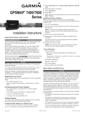
Installation Instructions
Page 1
... card slot on -screen instructions. 4 Wait several minutes while the software update process completes. Using the included hardware and template, you can use the included bracket and hardware to bail mount the device, or you can use the included template and hardware to update the device software when you experience difficulty during the installation, contact Garmin® Product Support. Read all device...
... card slot on -screen instructions. 4 Wait several minutes while the software update process completes. Using the included hardware and template, you can use the included bracket and hardware to bail mount the device, or you can use the included template and hardware to update the device software when you experience difficulty during the installation, contact Garmin® Product Support. Read all device...

Installation Instructions
Page 3
... Fuse Battery 1.8 m (6 ft.) without the locking ring installed. To prevent the possibility of the wiring harness. 4 Connect the wiring harness to help avoid the interference. If you must be installed between the DVI port and DVI cable connector to avoid damage to the connectors. • For easer cable routing, the Garmin Marine Network cables, the power and NMEA® 0183 cables, and the transducer cable are used to...
... Fuse Battery 1.8 m (6 ft.) without the locking ring installed. To prevent the possibility of the wiring harness. 4 Connect the wiring harness to help avoid the interference. If you must be installed between the DVI port and DVI cable connector to avoid damage to the connectors. • For easer cable routing, the Garmin Marine Network cables, the power and NMEA® 0183 cables, and the transducer cable are used to...

Installation Instructions
Page 4
... be used for Garmin Marine Network connections. ◦ Additional Garmin Marine Network cables and connectors are available from your boat to share data from the chartplotter to 100 mA. • To manually toggle visual and audible alerts, you do not have an existing NMEA 2000 network on the model. If you can create a basic one transmitting (Tx) wire or...
... be used for Garmin Marine Network connections. ◦ Additional Garmin Marine Network cables and connectors are available from your boat to share data from the chartplotter to 100 mA. • To manually toggle visual and audible alerts, you do not have an existing NMEA 2000 network on the model. If you can create a basic one transmitting (Tx) wire or...


