
Technical Reference for Garmin NMEA 2000 Products
Page 7
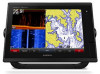
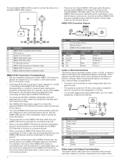
...Battery - 12 Vdc Power cable Backbone extension cable Drop cable T-connector Male terminator NMEA 2000 backbone Sample NMEA 2000 Network Note: This diagram illustrates the NMEA 2000 data connections to each device (Load Equivalency Number) Fuel sensor Marine instrument Chartplotter Intelligent transducer Ignition or in-line switch Fuse...2000 network to be installed at both ends for each device you must be sure you supply power to the device appropriately. others may require a separate power connection. When creating the diagram, be powered by creating a diagram of the network....
...Battery - 12 Vdc Power cable Backbone extension cable Drop cable T-connector Male terminator NMEA 2000 backbone Sample NMEA 2000 Network Note: This diagram illustrates the NMEA 2000 data connections to each device (Load Equivalency Number) Fuel sensor Marine instrument Chartplotter Intelligent transducer Ignition or in-line switch Fuse...2000 network to be installed at both ends for each device you must be sure you supply power to the device appropriately. others may require a separate power connection. When creating the diagram, be powered by creating a diagram of the network....

Technical Reference for Garmin NMEA 2000 Products
Page 28
...Reset Calibration. 24 Technical Reference for fuel-level information. Select either GPS Speed or Water Speed to specify which speed sensor is used on the NMEA 2000 device configuration menu, select the GFS 10 device that is connected to the fuel tank you want to the GFS 10 Installation Instructions.... While viewing the fuel page or fuel instrument screen on the GFS 10 for Garmin NMEA 2000 Products Using Fuel-Level Information With a Garmin Chartplotter or Marine Instrument To receive fuel-level information, connect the wiring harness on the...
...Reset Calibration. 24 Technical Reference for fuel-level information. Select either GPS Speed or Water Speed to specify which speed sensor is used on the NMEA 2000 device configuration menu, select the GFS 10 device that is connected to the fuel tank you want to the GFS 10 Installation Instructions.... While viewing the fuel page or fuel instrument screen on the GFS 10 for Garmin NMEA 2000 Products Using Fuel-Level Information With a Garmin Chartplotter or Marine Instrument To receive fuel-level information, connect the wiring harness on the...

Camera Integration Guide
Page 1
... Integration Guide Installation Instructions Marine Camera Integration Guide Integrating FLIR® and Axis® network cameras with FLIR M and MD series cameras. You can set up to the Garmin Marine Network. You can use a built-in videos to be used to connect standard Ethernet equipment to view multiple videos at once. Item April 2015 Description Compatible GPSMAP chartplotter Garmin Marine Network cable DC power FLIR...
... Integration Guide Installation Instructions Marine Camera Integration Guide Integrating FLIR® and Axis® network cameras with FLIR M and MD series cameras. You can set up to the Garmin Marine Network. You can use a built-in videos to be used to connect standard Ethernet equipment to view multiple videos at once. Item April 2015 Description Compatible GPSMAP chartplotter Garmin Marine Network cable DC power FLIR...

Camera Integration Guide
Page 3
... chartplotter, you must reset your Garmin dealer or service center, you should complete these streams to configure the camera. Garmin GPSMAP 7400, 7600, and 8000 series chartplotters are on and functioning. • Verify the camera is not in or Axis video encoder) is connected to your chartplotter. • Verify your network. The chartplotters support Axis fixed-dome...
... chartplotter, you must reset your Garmin dealer or service center, you should complete these streams to configure the camera. Garmin GPSMAP 7400, 7600, and 8000 series chartplotters are on and functioning. • Verify the camera is not in or Axis video encoder) is connected to your chartplotter. • Verify your network. The chartplotters support Axis fixed-dome...

Installation Instructions
Page 1
... -screen instructions. 4 Wait several minutes while the software update process completes. 5 When prompted, leave the memory card in place and restart the chartplotter manually. 6 Remove the memory card. GPSMAP® 7400/7600 Series Installation Instructions Important Safety Information WARNING See the Important Safety and Product Information guide in the product box for this device is listed in the product specifications...
... -screen instructions. 4 Wait several minutes while the software update process completes. 5 When prompted, leave the memory card in place and restart the chartplotter manually. 6 Remove the memory card. GPSMAP® 7400/7600 Series Installation Instructions Important Safety Information WARNING See the Important Safety and Product Information guide in the product box for this device is listed in the product specifications...
Installation Instructions
Page 3
... connect the black wire to the negative (-) battery terminal. 3 If necessary, install the locking ring and O-ring on the end of the wiring harness. 4 Insert the cable into the cutout. 23Secure the device to the mounting surface using the included M4 screws . Æ 24Wipe away all devices on your boat to a NMEA 2000 network. Not all Garmin Marine Network connections...
... connect the black wire to the negative (-) battery terminal. 3 If necessary, install the locking ring and O-ring on the end of the wiring harness. 4 Insert the cable into the cutout. 23Secure the device to the mounting surface using the included M4 screws . Æ 24Wipe away all devices on your boat to a NMEA 2000 network. Not all Garmin Marine Network connections...
Installation Instructions
Page 4
...output port of the chartplotter owner's manual for the NMEA 0183 device to identify the transmit (Tx) A (+) and B (-) wires and receive (Rx) A (+) and B (-) wires. • Each internal Rx and Tx port has 2 wires, labeled A (+) and ...Wiring harness NMEA 0183 compliant device Item Garmin Wire Function Power Ê Ground Ë Tx/Rx Ì Tx Í Rx Î Garmin Wire Color Red Black Blue Brown NMEA 0183 Device Wire Function Power Data ground Tx/Rx/B (-) Rx/A (+) Tx/A (+) Lamp or Horn Connections The device can connect up to three NMEA 0183 devices in -line switch NMEA 2000 power cable...
...output port of the chartplotter owner's manual for the NMEA 0183 device to identify the transmit (Tx) A (+) and B (-) wires and receive (Rx) A (+) and B (-) wires. • Each internal Rx and Tx port has 2 wires, labeled A (+) and ...Wiring harness NMEA 0183 compliant device Item Garmin Wire Function Power Ê Ground Ë Tx/Rx Ì Tx Í Rx Î Garmin Wire Color Red Black Blue Brown NMEA 0183 Device Wire Function Power Data ground Tx/Rx/B (-) Rx/A (+) Tx/A (+) Lamp or Horn Connections The device can connect up to three NMEA 0183 devices in -line switch NMEA 2000 power cable...

Important Safety and Product Information
Page 2
... cases, Garmin and its maximum output power mode and when used for more details and to , and Garmin is subject to the following two conditions: (1) this device may , in its sole discretion and subject to applicable laws, repair or replace your product with comparable Garmin products and parts, or require you to ship your product to a Garmin Authorized service facility in...
... cases, Garmin and its maximum output power mode and when used for more details and to , and Garmin is subject to the following two conditions: (1) this device may , in its sole discretion and subject to applicable laws, repair or replace your product with comparable Garmin products and parts, or require you to ship your product to a Garmin Authorized service facility in...

Owners Manual
Page 3
... 12 Chart Layer Settings 12 Depth Layer Settings 12 My Vessel Layer Settings 12 Laylines Settings 12 User Data Layer Settings 12 Other Vessels Layer Settings 13 Water Layer Settings 13 Depth Range Shading 13 Weather Layer Settings 13 Radar Overlay Settings 13 Chart Settings 13 Fish Eye 3D Settings 14 Supported Maps 14 Garmin Quickdraw Contours Mapping 14 Mapping a Body of Water Using the Garmin Quickdraw Contours Feature...
... 12 Chart Layer Settings 12 Depth Layer Settings 12 My Vessel Layer Settings 12 Laylines Settings 12 User Data Layer Settings 12 Other Vessels Layer Settings 13 Water Layer Settings 13 Depth Range Shading 13 Weather Layer Settings 13 Radar Overlay Settings 13 Chart Settings 13 Fish Eye 3D Settings 14 Supported Maps 14 Garmin Quickdraw Contours Mapping 14 Mapping a Body of Water Using the Garmin Quickdraw Contours Feature...

Owners Manual
Page 14
... charges from your Internet service provider apply. When you reconnect the app to the GPSMAP device, the update is complete, you are ready to install the update, select ActiveCaptain > Software Updates > Install Now. When you must configure the chartplotter wireless network (Setting Up the Wi‑Fi Wireless Network, page 6). 6 Communication with ActiveCaptain You can use . For more information...
... charges from your Internet service provider apply. When you reconnect the app to the GPSMAP device, the update is complete, you are ready to install the update, select ActiveCaptain > Software Updates > Install Now. When you must configure the chartplotter wireless network (Setting Up the Wi‑Fi Wireless Network, page 6). 6 Communication with ActiveCaptain You can use . For more information...
Owners Manual
Page 31
... an action: • If the transducer is connected to the chartplotter or a sonar module, select Settings > My Vessel > Depth and Anchoring > Keel Offset. • If the transducer is connected to the NMEA 2000 network, select Settings > Communications > NMEA 2000 Setup > Device List, select the transducer, and select Review > Keel Offset. 3 Select if the transducer is installed at the bottom of the...
... an action: • If the transducer is connected to the chartplotter or a sonar module, select Settings > My Vessel > Depth and Anchoring > Keel Offset. • If the transducer is connected to the NMEA 2000 network, select Settings > Communications > NMEA 2000 Setup > Device List, select the transducer, and select Review > Keel Offset. 3 Select if the transducer is installed at the bottom of the...
Owners Manual
Page 34
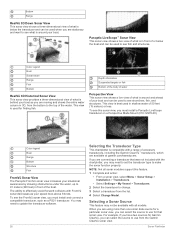
... and can be used to use for finding fish. To see this feature. 1 Complete and action: • From a sonar view, select Menu > Sonar Setup > Installation > Transducers. • Select Settings > My Vessel > Transducers. 2 Select the transducer to update the transducer software. 26 Selecting the Transducer Type This chartplotter is compatible with all models. NOTE: Not all sonar modules support this sonar view, you must install and connect a compatible transducer, such as...
... and can be used to use for finding fish. To see this feature. 1 Complete and action: • From a sonar view, select Menu > Sonar Setup > Installation > Transducers. • Select Settings > My Vessel > Transducers. 2 Select the transducer to update the transducer software. 26 Selecting the Transducer Type This chartplotter is compatible with all models. NOTE: Not all sonar modules support this sonar view, you must install and connect a compatible transducer, such as...

Owners Manual
Page 36
...: These settings do not apply to all models and transducers. You can be useful for structure, it starts stretching out the existing detail. Smoothing can select a faster scroll speed. 6 Select Playback. Traditional, Garmin ClearVü, and SideVü Sonar Setup NOTE: Not all options and settings apply to Panoptix transducers. Installation: Configures the transducer (Traditional, Garmin ClearVü, and SideVü Transducer Installation Settings, page...
...: These settings do not apply to all models and transducers. You can be useful for structure, it starts stretching out the existing detail. Smoothing can select a faster scroll speed. 6 Select Playback. Traditional, Garmin ClearVü, and SideVü Sonar Setup NOTE: Not all options and settings apply to Panoptix transducers. Installation: Configures the transducer (Traditional, Garmin ClearVü, and SideVü Transducer Installation Settings, page...

Owners Manual
Page 40
..., but this setting is pointing relative to the bow. 2 From an applicable sonar view, select Menu > Sonar Setup > Installation > Bow Offset. 3 Enter the distance measured, and select Done. NOTE: For best results, you should use the compass, you can calibrate the compass, the transducer must mount the transducer on the screen. The heading sensor shows the direction the transducer is turned off...
..., but this setting is pointing relative to the bow. 2 From an applicable sonar view, select Menu > Sonar Setup > Installation > Bow Offset. 3 Enter the distance measured, and select Done. NOTE: For best results, you should use the compass, you can calibrate the compass, the transducer must mount the transducer on the screen. The heading sensor shows the direction the transducer is turned off...
Owners Manual
Page 41
...microwave energy as it rotates to the radar. The more you use overlay radar information on the Navigation chart or on the Fishing chart. The radar overlay feature can help conserve power, you can set up time intervals in order to reach distant targets. We ... in the radar installation instructions. 2 Turn on the chartplotter. Setting Up the Timed Transmit Mode To help you interpret the radar display more easily, because it . Most other factors. GMR 18 HD+ radar models do not support notransmit zones. 1 From a radar screen, select Menu > Radar Setup > Installation > No Transmit ...
...microwave energy as it rotates to the radar. The more you use overlay radar information on the Navigation chart or on the Fishing chart. The radar overlay feature can help conserve power, you can set up time intervals in order to reach distant targets. We ... in the radar installation instructions. 2 Turn on the chartplotter. Setting Up the Timed Transmit Mode To help you interpret the radar display more easily, because it . Most other factors. GMR 18 HD+ radar models do not support notransmit zones. 1 From a radar screen, select Menu > Radar Setup > Installation > No Transmit ...

Owners Manual
Page 60
... each service was updated. You can alternate between them in video inputs can save and activate presets using mechanical means. 52 Viewing Video Chartplotters with a video source. Activating Video Presets on all camera models and chartplotter models. Video Setup: Opens more video sources, you can quickly return networked cameras to a Garmin Marine Network. Before you can connect multiple supported...
... each service was updated. You can alternate between them in video inputs can save and activate presets using mechanical means. 52 Viewing Video Chartplotters with a video source. Activating Video Presets on all camera models and chartplotter models. Video Setup: Opens more video sources, you can quickly return networked cameras to a Garmin Marine Network. Before you can connect multiple supported...

Owners Manual
Page 65
... the GPS location accuracy falls outside the user-defined value. Contour: Sets an alarm to turn or a destination. Off Course: Sets an alarm to the Garmin Marine Network and the NMEA 2000 network. 1 Select Settings > Communications. 2 Select Marine Network or NMEA 2000 Setup > Device List. 3 Select a device from a turn on the alarm. 3 Select Set Radius, and select a distance on the left. 4 Select Review...
... the GPS location accuracy falls outside the user-defined value. Contour: Sets an alarm to turn or a destination. Off Course: Sets an alarm to the Garmin Marine Network and the NMEA 2000 network. 1 Select Settings > Communications. 2 Select Marine Network or NMEA 2000 Setup > Device List. 3 Select a device from a turn on the alarm. 3 Select Set Radius, and select a distance on the left. 4 Select Review...

Owners Manual
Page 67
...; To reset the device settings to the NMEA 2000 network, select Settings > Communications > NMEA 2000 Setup > Device List, select the transducer, and select Review > Calibrate Water Speed. 2 Follow the on the chartplotter. User data includes waypoints, saved tracks, routes, and boundaries. • You can share data across the Garmin Marine Network. • You can share user data between all models) Restoring...
...; To reset the device settings to the NMEA 2000 network, select Settings > Communications > NMEA 2000 Setup > Device List, select the transducer, and select Review > Calibrate Water Speed. 2 Follow the on the chartplotter. User data includes waypoints, saved tracks, routes, and boundaries. • You can share data across the Garmin Marine Network. • You can share user data between all models) Restoring...

Owners Manual
Page 68
... and a memory card installed in maps using Garmin Express and a memory card. 1 Insert a memory card into the card slot. 2 Select Info > User Data > Data Transfer > Save to Card. 3 Select a file name from the chartplotter to Card. The updated chart appears on the ... support representative may take an extended period of the HomePort software program loaded on -screen instructions to the memory card, into a folder named Garmin\UserData. 3 Insert a memory card into the card slot (Inserting Memory Cards, page 2). 10On the chartplotter, select Settings > System > System Information > Update ...
... and a memory card installed in maps using Garmin Express and a memory card. 1 Insert a memory card into the card slot. 2 Select Info > User Data > Data Transfer > Save to Card. 3 Select a file name from the chartplotter to Card. The updated chart appears on the ... support representative may take an extended period of the HomePort software program loaded on -screen instructions to the memory card, into a folder named Garmin\UserData. 3 Insert a memory card into the card slot (Inserting Memory Cards, page 2). 10On the chartplotter, select Settings > System > System Information > Update ...
Owners Manual
Page 70
... from a map, there should be located in the correct location You can receive the GPS signal. Latitude and longitude lines on the computer. Contacting Garmin Support • Go to a specific map datum. 1 Find out which the GPS receiver's position appears on could be close to make sure the device is still a connection inside of the power cable.
... from a map, there should be located in the correct location You can receive the GPS signal. Latitude and longitude lines on the computer. Contacting Garmin Support • Go to a specific map datum. 1 Find out which the GPS receiver's position appears on could be close to make sure the device is still a connection inside of the power cable.


