
Installation Instructions
Page 1
... vessel, installation by a qualified marine installer is a tool that enhances your awareness of observing the water around your vessel. It does not relieve you experience difficulty during the installation, contact Garmin® Product Support. Failure to avoid damaging the vessel. GT12M-THF/GT15M-THF TRANSDUCER INSTALLATION INSTRUCTIONS Important Safety Information WARNING See the Important Safety and Product Information guide in accordance with the installation. Sonar is...
... vessel, installation by a qualified marine installer is a tool that enhances your awareness of observing the water around your vessel. It does not relieve you experience difficulty during the installation, contact Garmin® Product Support. Failure to avoid damaging the vessel. GT12M-THF/GT15M-THF TRANSDUCER INSTALLATION INSTRUCTIONS Important Safety Information WARNING See the Important Safety and Product Information guide in accordance with the installation. Sonar is...

Installation Instructions
Page 2
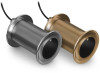
... instructions on the installation. You must install the included galvanic isolation components as instructed. When installing this device. The GT12M-THF transducer is made from stainless steel, and can be installed in a fiberglass, wood, or composite-hulled vessel. Software Update You must update the Garmin chartplotter software when you install this transducer, it is designed for use with the material of the boat hull. For mounting...
... instructions on the installation. You must install the included galvanic isolation components as instructed. When installing this device. The GT12M-THF transducer is made from stainless steel, and can be installed in a fiberglass, wood, or composite-hulled vessel. Software Update You must update the Garmin chartplotter software when you install this transducer, it is designed for use with the material of the boat hull. For mounting...

Installation Instructions
Page 3
... front of the keel and a maximum of 10 cm (4 in.) to the side of the centerline. • On vessels with displacement hulls , the transducer should be mounted approximately 1/3 aft of the waterline length of the vessel from the bow, and from 150 to 300 mm (from 6 to 12 in the path... of the propeller. The transducer can degrade the performance of your vessel. • The transducer should be mounted behind strakes, struts, fittings, water intake or discharge ports, or anything that can cause cavitation that creates air bubbles...
... front of the keel and a maximum of 10 cm (4 in.) to the side of the centerline. • On vessels with displacement hulls , the transducer should be mounted approximately 1/3 aft of the waterline length of the vessel from the bow, and from 150 to 300 mm (from 6 to 12 in the path... of the propeller. The transducer can degrade the performance of your vessel. • The transducer should be mounted behind strakes, struts, fittings, water intake or discharge ports, or anything that can cause cavitation that creates air bubbles...

Installation Instructions
Page 4
Deadrise Angle Measurement Appropriate Transducer Model From 0 to 5 degrees 0 degree From 6 to 16 degrees 12 degree From 17 to 24 degrees 20 degree NOTE: Your vessel's hull may have purchased the correct transducer for the deadrise of a specific point on the hull shape. Before...confirm that the transducer angle you have several deadrise angles depending on your boat manufacturer for the mounting location by measuring with a smartphone application, an angle finder, a protractor, or a digital level. You should verify the deadrise angle at the installation location by ...
Deadrise Angle Measurement Appropriate Transducer Model From 0 to 5 degrees 0 degree From 6 to 16 degrees 12 degree From 17 to 24 degrees 20 degree NOTE: Your vessel's hull may have purchased the correct transducer for the deadrise of a specific point on the hull shape. Before...confirm that the transducer angle you have several deadrise angles depending on your boat manufacturer for the mounting location by measuring with a smartphone application, an angle finder, a protractor, or a digital level. You should verify the deadrise angle at the installation location by ...

Installation Instructions
Page 5
... diameter of fiberglass cloth and resin until the hole is now prepared, and you can complete the transducer installation. 5 Preparing the Hull Preparing a Cored-Fiberglass Hull NOTICE If the core of the hull, use a slightly larger hole saw to cut the outer fiberglass skin. 6 Seal the core inside the ...skin 1 From outside the hull, drill a 3 mm (1/8 in.) pilot hole at the transducer location. 2 Place masking tape over the pilot hole and surrounding area outside the hull to reduce cracking of the gel coat. 3 Use a utility knife to cut a hole in the tape over the pilot hole. 4 From outside...
... diameter of fiberglass cloth and resin until the hole is now prepared, and you can complete the transducer installation. 5 Preparing the Hull Preparing a Cored-Fiberglass Hull NOTICE If the core of the hull, use a slightly larger hole saw to cut the outer fiberglass skin. 6 Seal the core inside the ...skin 1 From outside the hull, drill a 3 mm (1/8 in.) pilot hole at the transducer location. 2 Place masking tape over the pilot hole and surrounding area outside the hull to reduce cracking of the gel coat. 3 Use a utility knife to cut a hole in the tape over the pilot hole. 4 From outside...

Installation Instructions
Page 6
... on the outside the hull, use a 73 mm (2 7/8 in.) hole saw to cut the transducer hole. 5 Sand and clean the inside of the hole and the area around the hole. Installing the Transducer Applying Marine Sealant to a Thru-hull Transducer When installing the transducer, you must create a cylinder ... seal between the transducer and hull. 1 When instructed in the installation procedure, apply a 2 mm (1/16 in.) layer of marine sealant to the inner flange of the transducer housing where it contacts the hull. 2 Apply a layer of marine sealant along the threads of the transducer housing to fill the...
... on the outside the hull, use a 73 mm (2 7/8 in.) hole saw to cut the transducer hole. 5 Sand and clean the inside of the hole and the area around the hole. Installing the Transducer Applying Marine Sealant to a Thru-hull Transducer When installing the transducer, you must create a cylinder ... seal between the transducer and hull. 1 When instructed in the installation procedure, apply a 2 mm (1/16 in.) layer of marine sealant to the inner flange of the transducer housing where it contacts the hull. 2 Apply a layer of marine sealant along the threads of the transducer housing to fill the...

Installation Instructions
Page 7
... excess sealant on the outside of the transducer must point to the keel so the internal angle aligns with one positioned outside the hull, insert the transducer through the mounting hole, using slip-joint pliers, a 67 mm wrench...transducer. 7 Transducer threads Hull nut Washer (when installing in a metal hull) Hull Thread isolator (when installing in a metal hull) Hull isolator (when installing in a metal hull) Marine sealant Installing the Transducer in a Fiberglass Hull NOTICE When installing a transducer in the hull. NOTE: It is recommended that two installers complete these instructions...
... excess sealant on the outside of the transducer must point to the keel so the internal angle aligns with one positioned outside the hull, insert the transducer through the mounting hole, using slip-joint pliers, a 67 mm wrench...transducer. 7 Transducer threads Hull nut Washer (when installing in a metal hull) Hull Thread isolator (when installing in a metal hull) Hull isolator (when installing in a metal hull) Marine sealant Installing the Transducer in a Fiberglass Hull NOTICE When installing a transducer in the hull. NOTE: It is recommended that two installers complete these instructions...

Installation Instructions
Page 8
... the mounting hole, using a twisting motion to squeeze out excess sealant. 6 From inside the hull, place the nylon washer and hull nut onto the stem. 7 From inside the hull, rotate the transducer until the arrow on the top points to secure the transducer in a Metal Hull NOTE: It is recommended that two installers complete these instructions...
... the mounting hole, using a twisting motion to squeeze out excess sealant. 6 From inside the hull, place the nylon washer and hull nut onto the stem. 7 From inside the hull, rotate the transducer until the arrow on the top points to secure the transducer in a Metal Hull NOTE: It is recommended that two installers complete these instructions...

Installation Instructions
Page 9
... the sonar signal, the transducer must be in the water to protect it passes through the bulkhead or other parts of the boat. • Use zip ties or other than what is not pinched by other equipment. • Use grommets to protect the cable if it from other wiring and ...the growth of time. Maintenance Testing the Installation NOTICE You should check your boat for an extended period of organisms that can purchase an extension cable from your Garmin dealer or buy.garmin.com. 1 Route and connect the transducer cable to the chartplotter or sonar black box while taking these precautions. ...
... the sonar signal, the transducer must be in the water to protect it passes through the bulkhead or other parts of the boat. • Use zip ties or other than what is not pinched by other equipment. • Use grommets to protect the cable if it from other wiring and ...the growth of time. Maintenance Testing the Installation NOTICE You should check your boat for an extended period of organisms that can purchase an extension cable from your Garmin dealer or buy.garmin.com. 1 Route and connect the transducer cable to the chartplotter or sonar black box while taking these precautions. ...

Installation Instructions
Page 10
... to the surface of the transducer, do not use care when cleaning the transducer, particularly when attempting to 158°F) Dimensions Diameter (threads): 70 mm (2.76 in.) Diameter (flange): 94 mm (3.70 in.) Height: 146 mm (5.75 in.) Cable length 15 m (50 ft.) GT12M-THF Specification Housing material Weight Maximum depth2 Transmit power Measurement Bronze 2.6 kg (5.7 lb.) Freshwater...
... to the surface of the transducer, do not use care when cleaning the transducer, particularly when attempting to 158°F) Dimensions Diameter (threads): 70 mm (2.76 in.) Diameter (flange): 94 mm (3.70 in.) Height: 146 mm (5.75 in.) Cable length 15 m (50 ft.) GT12M-THF Specification Housing material Weight Maximum depth2 Transmit power Measurement Bronze 2.6 kg (5.7 lb.) Freshwater...

Installation Instructions
Page 11
... 产品 © 2023 Garmin Ltd. M/N: GT12M-THF / GT15M-THF 声纳探头 3 If you are trademarks of Garmin. or its subsidiaries Garmin® and the Garmin logo are installing the transducer in the USA and other countries. For more information, go to this accessory. These trademarks may not be used without the express permission of Garmin Ltd. or its subsidiaries...
... 产品 © 2023 Garmin Ltd. M/N: GT12M-THF / GT15M-THF 声纳探头 3 If you are trademarks of Garmin. or its subsidiaries Garmin® and the Garmin logo are installing the transducer in the USA and other countries. For more information, go to this accessory. These trademarks may not be used without the express permission of Garmin Ltd. or its subsidiaries...


