Service Guide
Page 3
Table of Contents About This Service Guide Outstanding New Features New Features / Design Features and Specifications Cook Top / Surface Burners Conversion & Orifice information Control Panel Access ERC III Special Features True Temp™ Design ERC On-Board Diagnostics Lock Motor Circuit & Diagnostics Schematics / Strip Circuits / Diagnostics Illustrated Parts Information Flow Chart - Bake / Broil Circuit TECHNICAL SERVICE GUIDE NEW 30" XL44™ SERIES RANGES FEATURING TRUE TEMP™ COOKING 2 3-6 7 8-9 10 11-12 13 14-15 16 17-18 19 20-24 25-30 31 - 1 -
Table of Contents About This Service Guide Outstanding New Features New Features / Design Features and Specifications Cook Top / Surface Burners Conversion & Orifice information Control Panel Access ERC III Special Features True Temp™ Design ERC On-Board Diagnostics Lock Motor Circuit & Diagnostics Schematics / Strip Circuits / Diagnostics Illustrated Parts Information Flow Chart - Bake / Broil Circuit TECHNICAL SERVICE GUIDE NEW 30" XL44™ SERIES RANGES FEATURING TRUE TEMP™ COOKING 2 3-6 7 8-9 10 11-12 13 14-15 16 17-18 19 20-24 25-30 31 - 1 -
Service Guide
Page 21
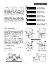
...position. UNLOCKED mode A Contacts Open Rear Moving toward LOCKED mode B Contacts Open Rear Front Contacts Closed Front Contacts Open LOCK MOTOR CYCLE C D Contacts Closed Rear Contacts Open Rear Front Contacts Open LOCKED mode Front Contacts Open Moving toward UNLOCKED Rear switch ... contacts open Front contacts closed (light switch depressed). When the SELF CLEAN cycle is thermally Controlled. LOCK MOTOR CIRCUIT 5 LOCK MOTOR CYCLE TEST - LOCK MOTOR ACCESS Remove the cooktop following the steps outlined on the lock mechanism signal the control board to UNLOCKED POSITION...
...position. UNLOCKED mode A Contacts Open Rear Moving toward LOCKED mode B Contacts Open Rear Front Contacts Closed Front Contacts Open LOCK MOTOR CYCLE C D Contacts Closed Rear Contacts Open Rear Front Contacts Open LOCKED mode Front Contacts Open Moving toward UNLOCKED Rear switch ... contacts open Front contacts closed (light switch depressed). When the SELF CLEAN cycle is thermally Controlled. LOCK MOTOR CIRCUIT 5 LOCK MOTOR CYCLE TEST - LOCK MOTOR ACCESS Remove the cooktop following the steps outlined on the lock mechanism signal the control board to UNLOCKED POSITION...

Service Guide
Page 22
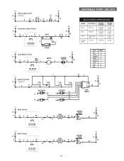
... RATING SEE RATING PLATE V N D2 V W A2 W RF SW RR SW D1 R LF SW LR SW RIGHT IGNITER RF RR V LEFT IGNITER LF LR MOTOR R W W W W PLUNGER SWITCH L N W W SPARK MODULE W CONTROL VALVE N BROIL W GLOWBAR W B2 N W E4 B1 CONTROL VALVE E6 Y C1 W BAKE GLOWBAR W C2 W L-1 SL ... ORANGE GREEN YELLOW VIOLET BLUE GRAY SYMBOL R W O G Y V N S REAR LATCH SWITCH * CLOSED when door is LOCKED * OPEN when door is UNLOCKED LOCK MOTOR ASSEMBLY FRONT LATCH SWITCH * CLOSED when door is UNLOCKED * OPEN when door is LOCKED LOCKED UNLOCKED 1100W at 75°F. 2634W at 865° F. F2...
... RATING SEE RATING PLATE V N D2 V W A2 W RF SW RR SW D1 R LF SW LR SW RIGHT IGNITER RF RR V LEFT IGNITER LF LR MOTOR R W W W W PLUNGER SWITCH L N W W SPARK MODULE W CONTROL VALVE N BROIL W GLOWBAR W B2 N W E4 B1 CONTROL VALVE E6 Y C1 W BAKE GLOWBAR W C2 W L-1 SL ... ORANGE GREEN YELLOW VIOLET BLUE GRAY SYMBOL R W O G Y V N S REAR LATCH SWITCH * CLOSED when door is LOCKED * OPEN when door is UNLOCKED LOCK MOTOR ASSEMBLY FRONT LATCH SWITCH * CLOSED when door is UNLOCKED * OPEN when door is LOCKED LOCKED UNLOCKED 1100W at 75°F. 2634W at 865° F. F2...
Service Guide
Page 23
...LP D1 R RK SW O D3 O N A2 W W L-1 Flourecent Light Circuit A1 R E1 R L-1 SL G FLUOR LT O B ERC BOARD Relay Energized L-1 Lock Motor Circuit A1 R E1 R L-1 DOOR MOTOR V B STARTER MOTOR R N A2 W W 240 N PLUNGER A2 SWITCH W W ERC BOARD Relay Energized L-1 Igniter Circuits A1 Shown with RF Switch ON R R D1 R RF SW V RR... LF W W W LR JGBP85BEA STRIP CIRCUITS RELAY CONTACT OPERATION TEST Relay Bake Broil Latch Surface Light Terminals BA to N BR to N Door Motor to N SL to N Voltage in Mode 120 VAC in Bake 120 VAC in Broil 120 VAC 120 VAC Voltage in Off 0 VAC in ...
...LP D1 R RK SW O D3 O N A2 W W L-1 Flourecent Light Circuit A1 R E1 R L-1 SL G FLUOR LT O B ERC BOARD Relay Energized L-1 Lock Motor Circuit A1 R E1 R L-1 DOOR MOTOR V B STARTER MOTOR R N A2 W W 240 N PLUNGER A2 SWITCH W W ERC BOARD Relay Energized L-1 Igniter Circuits A1 Shown with RF Switch ON R R D1 R RF SW V RR... LF W W W LR JGBP85BEA STRIP CIRCUITS RELAY CONTACT OPERATION TEST Relay Bake Broil Latch Surface Light Terminals BA to N BR to N Door Motor to N SL to N Voltage in Mode 120 VAC in Bake 120 VAC in Broil 120 VAC 120 VAC Voltage in Off 0 VAC in ...

Service Guide
Page 24
... other than 2900 ohms during bake broil or clean Shorted sensor; F. F. sensor resistance exceeds 2900 ohms during bake broil or clean Door motor safety circuit ERC Membrane switch ERC Membrane switch ERC High resistance connection in sensor circuit ERC (welded bake relay contacts) High resistance connection in.... TrueTemp ERC III WITH TRUE TEMP™ AND SMARTLOGIC™ ERC RELAY CONTACT OPERATION TEST Relay / Mode Bake Broil Door Motor Surface Light Terminals BA to N BR to N Door Motor to N SL to 90 ohms. An "OPEN" circuit would indicate a defect in the touch pad. above 915 deg....
... other than 2900 ohms during bake broil or clean Shorted sensor; F. F. sensor resistance exceeds 2900 ohms during bake broil or clean Door motor safety circuit ERC Membrane switch ERC Membrane switch ERC High resistance connection in sensor circuit ERC (welded bake relay contacts) High resistance connection in.... TrueTemp ERC III WITH TRUE TEMP™ AND SMARTLOGIC™ ERC RELAY CONTACT OPERATION TEST Relay / Mode Bake Broil Door Motor Surface Light Terminals BA to N BR to N Door Motor to N SL to 90 ohms. An "OPEN" circuit would indicate a defect in the touch pad. above 915 deg....