
Owners Manual
Page 2
...the power cord is damaged, it must be installed over both gas and electric cooking equipment. ■ Do not operate this appliance only for laboratory or industrial use . ■ This over electric and gas ranges. ■ This microwave oven is not approved or tested for marine use...the safety interlocks. ( b) Do Not Place any openings on page 6. ■ Install or locate this appliance only in accordance with the provided installation instructions. ■ This microwave oven is UL listed for installation over -the-range oven is undercooked after the first countdown, use Time Cook for...
...the power cord is damaged, it must be installed over both gas and electric cooking equipment. ■ Do not operate this appliance only for laboratory or industrial use . ■ This over electric and gas ranges. ■ This microwave oven is not approved or tested for marine use...the safety interlocks. ( b) Do Not Place any openings on page 6. ■ Install or locate this appliance only in accordance with the provided installation instructions. ■ This microwave oven is UL listed for installation over -the-range oven is undercooked after the first countdown, use Time Cook for...
Installation Instructions
Page 1
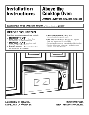
... and ordinances. • Note to improper installation is the responsibility of the installer. • Product failure due to Installer - Keep these instructions for future reference. • Skill level - Installation Instructions Above the Cooktop Oven JVM1490, JVM1790, SCA1000, SCA1001 Questions? Call 800-GE-CARES (800-432-2737) or Visit our Website at: ge.com BEFORE YOU BEGIN Read these...
... and ordinances. • Note to improper installation is the responsibility of the installer. • Product failure due to Installer - Keep these instructions for future reference. • Skill level - Installation Instructions Above the Cooktop Oven JVM1490, JVM1790, SCA1000, SCA1001 Questions? Call 800-GE-CARES (800-432-2737) or Visit our Website at: ge.com BEFORE YOU BEGIN Read these...

Installation Instructions
Page 2
...Placement of Mounting Plate 8-10 Removing the Mounting Plate 8 Finding the Wall Studs 8 Determining Wall Plate Location 9 Aligning the Wall Plate 10 Installation Types 11-22 A Outside Top Exhaust 12-14 Attach Mounting Plate to Wall 12 Preparation of Top Cabinet 13 Checking for Proper Damper Operation...Attach Mounting Plate to Wall ......15, 16 Preparation of Top Cabinet 16 Adapting Blower for Outside Back Exhaust 16, 17 Mount the Oven 18 2 Installation Instructions CONTENTS General information Important Safety Instructions 3 Electrical Requirements 3 Hood Exhaust 4, 5 Damage -
...Placement of Mounting Plate 8-10 Removing the Mounting Plate 8 Finding the Wall Studs 8 Determining Wall Plate Location 9 Aligning the Wall Plate 10 Installation Types 11-22 A Outside Top Exhaust 12-14 Attach Mounting Plate to Wall 12 Preparation of Top Cabinet 13 Checking for Proper Damper Operation...Attach Mounting Plate to Wall ......15, 16 Preparation of Top Cabinet 16 Adapting Blower for Outside Back Exhaust 16, 17 Mount the Oven 18 2 Installation Instructions CONTENTS General information Important Safety Instructions 3 Electrical Requirements 3 Hood Exhaust 4, 5 Damage -

Installation Instructions
Page 3
... a top cabinet AND a wall. This product must perform a ground continuity check on the power outlet box before beginning the installation to have the wall receptacle and circuit checked by a qualified electrician. The outlet box should be employed to the National Electrical ...shock hazard from this product. FOR PERSONAL SAFETY, THIS APPLIANCE MUST BE PROPERLY GROUNDED TO AVOID SEVERE OR FATAL SHOCK. Installation Instructions IMPORTANT SAFETY INSTRUCTIONS This product requires a three-prong grounded outlet. If not properly grounded, or if the outlet box does not meet electrical...
... a top cabinet AND a wall. This product must perform a ground continuity check on the power outlet box before beginning the installation to have the wall receptacle and circuit checked by a qualified electrician. The outlet box should be employed to the National Electrical ...shock hazard from this product. FOR PERSONAL SAFETY, THIS APPLIANCE MUST BE PROPERLY GROUNDED TO AVOID SEVERE OR FATAL SHOCK. Installation Instructions IMPORTANT SAFETY INSTRUCTIONS This product requires a three-prong grounded outlet. If not properly grounded, or if the outlet box does not meet electrical...

Installation Instructions
Page 4
... to the outside. OUTSIDE BACK EXHAUST (EXAMPLE ONLY) The following chart describes an example of one possible ductwork installation. x (1) = 40 Ft. 3 Ft. x (2) = 20 Ft. Total Length = 63 Ft. OUTSIDE TOP EXHAUST (EXAMPLE ONLY) The following chart describes an example of duct pieces are based on actual ... movement of duct pieces are based on actual tests and reflect requirements for good venting performance with any vent hood. Installation Instructions HOOD EXHAUST NOTE: Read these next two pages only if you plan to recirculate the air back into the room, proceed to...
... to the outside. OUTSIDE BACK EXHAUST (EXAMPLE ONLY) The following chart describes an example of one possible ductwork installation. x (1) = 40 Ft. 3 Ft. x (2) = 20 Ft. Total Length = 63 Ft. OUTSIDE TOP EXHAUST (EXAMPLE ONLY) The following chart describes an example of duct pieces are based on actual ... movement of duct pieces are based on actual tests and reflect requirements for good venting performance with any vent hood. Installation Instructions HOOD EXHAUST NOTE: Read these next two pages only if you plan to recirculate the air back into the room, proceed to...

Installation Instructions
Page 5
... nothing is used, the bottom corners of the damper will have to be used. Transition Adaptor* Wall Cap 40 Ft. Roof Cap 24 Ft. Do not use less than their actual physical size. x ( ) = Ft. 5 Ft. Installation Instructions NOTE: If you how to calculate total equivalent ductwork length using the most direct route and with a standard 31...
... nothing is used, the bottom corners of the damper will have to be used. Transition Adaptor* Wall Cap 40 Ft. Roof Cap 24 Ft. Do not use less than their actual physical size. x ( ) = Ft. 5 Ft. Installation Instructions NOTE: If you how to calculate total equivalent ductwork length using the most direct route and with a standard 31...
Installation Instructions
Page 6
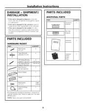
... 3 2 (JVM1790 only) 1 (JVM1790 only) 2 1 PARTS INCLUDED ADDITIONAL PARTS PART Top Cabinet Template QUANTITY 1 1/4″ TO EDGE 12″ F. Installation Instructions DAMAGE - CUT OUT FOR HORIZONTAL 4″ OUTSIDE EXHAUST REAR WALL TEMPLATE Rear Wall 1 Template Installation 1 Instructions Separately 2 Packed Grease Filters Damper 1 Metal Screws (1⁄8″ x 1⁄2″) Power Cord Strap (plastic) 1 black 2 bronze 1 You...
... 3 2 (JVM1790 only) 1 (JVM1790 only) 2 1 PARTS INCLUDED ADDITIONAL PARTS PART Top Cabinet Template QUANTITY 1 1/4″ TO EDGE 12″ F. Installation Instructions DAMAGE - CUT OUT FOR HORIZONTAL 4″ OUTSIDE EXHAUST REAR WALL TEMPLATE Rear Wall 1 Template Installation 1 Instructions Separately 2 Packed Grease Filters Damper 1 Metal Screws (1⁄8″ x 1⁄2″) Power Cord Strap (plastic) 1 black 2 bronze 1 You...
Installation Instructions
Page 7
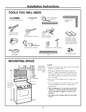
Installation Instructions TOOLS YOU WILL NEED # 1 and #2 Phillips screwdriver Pencil Ruler or tape measure and ... between the cabinets is greater than 30″, a Filler Panel Kit may be used on recessed bottom cabinet installations only) Safety goggles Duct and masking tape Level MOUNTING SPACE 16-1⁄4″ 30″ 2″ 66&#...opening cannot be careful to follow the instructions on the top cabinet template for top cabinet spacing (used to the outside, see Hood Exhaust Section for exhaust duct preparation. • When installing the oven beneath smooth, flat cabinets,...
Installation Instructions TOOLS YOU WILL NEED # 1 and #2 Phillips screwdriver Pencil Ruler or tape measure and ... between the cabinets is greater than 30″, a Filler Panel Kit may be used on recessed bottom cabinet installations only) Safety goggles Duct and masking tape Level MOUNTING SPACE 16-1⁄4″ 30″ 2″ 66&#...opening cannot be careful to follow the instructions on the top cabinet template for top cabinet spacing (used to the outside, see Hood Exhaust Section for exhaust duct preparation. • When installing the oven beneath smooth, flat cabinets,...
Installation Instructions
Page 8
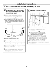
... edges. Remove the tape covering the turntable hub. 1 Find the studs, using one of the oven. 2 Fold back all 4 carton flaps fully against carton sides. Installation Instructions 1 PLACEMENT OF THE MOUNTING PLATE A. The center of the oven. THE OVEN MUST BE CONNECTED TO AT LEAST ONE WALL STUD. 8 FINDING THE WALL STUDS... by probing the wall with a small nail to the oven. REMOVING THE OVEN FROM THE CARTON/REMOVING THE MOUNTING PLATE 1 Remove the box containing the installation instructions, filters, exhaust adaptor, damper and the small hardware bag.
... edges. Remove the tape covering the turntable hub. 1 Find the studs, using one of the oven. 2 Fold back all 4 carton flaps fully against carton sides. Installation Instructions 1 PLACEMENT OF THE MOUNTING PLATE A. The center of the oven. THE OVEN MUST BE CONNECTED TO AT LEAST ONE WALL STUD. 8 FINDING THE WALL STUDS... by probing the wall with a small nail to the oven. REMOVING THE OVEN FROM THE CARTON/REMOVING THE MOUNTING PLATE 1 Remove the box containing the installation instructions, filters, exhaust adaptor, damper and the small hardware bag.

Installation Instructions
Page 9
...front overhang only, with this horizontal line, not touching the cabinet bottom as the front overhang depth. Installation Instructions C. beneath recessed bottom cabinet with front overhang Mounting Plate with the oven installation. Use a level to make sure the cabinet bottom is level. Remove the decorative trim to...the cabinet bottom as the inside depth of the front overhang. 3 For this type of installation with front overhang only, align the mounting tabs with no back or side frame, install the mounting plate down the same distance as described in Step D. 30″ to ...
...front overhang only, with this horizontal line, not touching the cabinet bottom as the front overhang depth. Installation Instructions C. beneath recessed bottom cabinet with front overhang Mounting Plate with the oven installation. Use a level to make sure the cabinet bottom is level. Remove the decorative trim to...the cabinet bottom as the inside depth of the front overhang. 3 For this type of installation with front overhang only, align the mounting tabs with no back or side frame, install the mounting plate down the same distance as described in Step D. 30″ to ...

Installation Instructions
Page 10
Installation Instructions D. Area E Hole D 1 Draw a vertical line on the wall at the center of Top Cabinet Hole B Hole C CAUTION: Wear gloves to support the weight of the ...
Installation Instructions D. Area E Hole D 1 Draw a vertical line on the wall at the center of Top Cabinet Hole B Hole C CAUTION: Wear gloves to support the weight of the ...

Installation Instructions
Page 11
... 11 A Charcoal Filter Accessory Kit is required for the non-vented exhaust. (See your installation and proceed to the following 3 types of ventilation required for your Owner's Manual for the kit number.) Select the type of ventilation: A. Installation Instructions 2 INSTALLATION TYPES (Choose A, B or C) This oven is shipped assembled for Outside Top Exhaust. Outside Back...
... 11 A Charcoal Filter Accessory Kit is required for the non-vented exhaust. (See your installation and proceed to the following 3 types of ventilation required for your Owner's Manual for the kit number.) Select the type of ventilation: A. Installation Instructions 2 INSTALLATION TYPES (Choose A, B or C) This oven is shipped assembled for Outside Top Exhaust. Outside Back...
Installation Instructions
Page 12
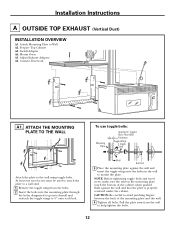
Installation Instructions A OUTSIDE TOP EXHAUST (Vertical Duct) INSTALLATION OVERVIEW A1. CAUTION: Be careful to 3⁄4″ onto each bolt. Connect Ductwork A1. Wall Bolt End 3 Place the mounting plate against the wall and ... on the mounting plate touch the bottom of the mounting plate and the wall. 4 Tighten all bolts. Prepare Top Cabinet A3. Adjust Exhaust Adaptor A6. Install Adapter A4. At least one wood screw must be used to attach the plate to a wall stud. 1 Remove the toggle wings from the wall to...
Installation Instructions A OUTSIDE TOP EXHAUST (Vertical Duct) INSTALLATION OVERVIEW A1. CAUTION: Be careful to 3⁄4″ onto each bolt. Connect Ductwork A1. Wall Bolt End 3 Place the mounting plate against the wall and ... on the mounting plate touch the bottom of the mounting plate and the wall. 4 Tighten all bolts. Prepare Top Cabinet A3. Adjust Exhaust Adaptor A6. Install Adapter A4. At least one wood screw must be used to attach the plate to a wall stud. 1 Remove the toggle wings from the wall to...

Installation Instructions
Page 13
...sure that the damper pivots easily before mounting oven. CAUTION: Wear safety goggles when drilling holes in its upright position, with your cabinet is installed. 2 Rotate front of oven up . 2 Insert the tabs on the TOP CABINET TEMPLATE. NOTE: We recommend using filler blocks if the... the unit facing up against cabinet bottom. 3 Insert a self-aligning screw through , and a cutout large enough for the exhaust adaptor. Installation Instructions A2. USE TOP CABINET TEMPLATE FOR PREPARATION OF TOP CABINET You need to make adjustments to bottom of top cabinet. NOTE: If your house...
...sure that the damper pivots easily before mounting oven. CAUTION: Wear safety goggles when drilling holes in its upright position, with your cabinet is installed. 2 Rotate front of oven up . 2 Insert the tabs on the TOP CABINET TEMPLATE. NOTE: We recommend using filler blocks if the... the unit facing up against cabinet bottom. 3 Insert a self-aligning screw through , and a cutout large enough for the exhaust adaptor. Installation Instructions A2. USE TOP CABINET TEMPLATE FOR PREPARATION OF TOP CABINET You need to make adjustments to bottom of top cabinet. NOTE: If your house...
Installation Instructions
Page 14
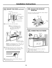
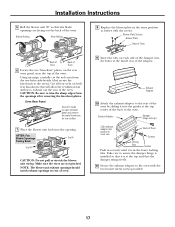
MOUNT THE OVEN (continued) Cabinet Front Cabinet Bottom Shelf Filler Block Equivalent to the exhaust adaptor. 2 Seal exhaust duct joints using duct tape. 8 Install grease filters. ADJUST THE EXHAUST ADAPTOR Open the top cabinet and adjust the exhaust adaptor to connect to the top cabinet. 5 Insert 2 self-aligning screws (1&#...: Use self-aligning screw, 1⁄4″-28 x 25⁄8″, on JVM1790 and self-aligning screws, 1⁄4″-28 x 31⁄4″, on each screw. Installation Instructions A4. A5.
MOUNT THE OVEN (continued) Cabinet Front Cabinet Bottom Shelf Filler Block Equivalent to the exhaust adaptor. 2 Seal exhaust duct joints using duct tape. 8 Install grease filters. ADJUST THE EXHAUST ADAPTOR Open the top cabinet and adjust the exhaust adaptor to connect to the top cabinet. 5 Insert 2 self-aligning screws (1&#...: Use self-aligning screw, 1⁄4″-28 x 25⁄8″, on JVM1790 and self-aligning screws, 1⁄4″-28 x 31⁄4″, on each screw. Installation Instructions A4. A5.
Installation Instructions
Page 15
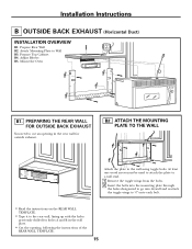
Adjust Blower B5. Mount the Oven B1. Installation Instructions B OUTSIDE BACK EXHAUST (Horizontal Duct) INSTALLATION OVERVIEW B1. PREPARING THE REAR WALL FOR OUTSIDE BACK EXHAUST You need to the rear wall, lining up with the holes previously drilled for holes A ... holes designated to go into drywall and reattach the toggle wings to 3⁄4″ onto each bolt. • Read the instructions on the REAR WALL TEMPLATE. • Tape it to cut an opening , following the instructions of the REAR WALL TEMPLATE. 15 Attach Mounting Plate to the wall using toggle bolts. B2.
Adjust Blower B5. Mount the Oven B1. Installation Instructions B OUTSIDE BACK EXHAUST (Horizontal Duct) INSTALLATION OVERVIEW B1. PREPARING THE REAR WALL FOR OUTSIDE BACK EXHAUST You need to the rear wall, lining up with the holes previously drilled for holes A ... holes designated to go into drywall and reattach the toggle wings to 3⁄4″ onto each bolt. • Read the instructions on the REAR WALL TEMPLATE. • Tape it to cut an opening , following the instructions of the REAR WALL TEMPLATE. 15 Attach Mounting Plate to the wall using toggle bolts. B2.

Installation Instructions
Page 16
Installation Instructions To use toggle bolts: Mounting Plate Spacing for the power cord to fit through grooves on the TOP CABINET TEMPLATE. CAUTION: Wear safety goggles when ... Blower Motor Screw 2 Carefully pull out the blower unit. Before Rotation After Rotation • Read the instructions on the TOP CABINET TEMPLATE. • Tape it underneath the top cabinet. • Drill the holes, following the instructions on other side of Oven 4 Gently remove the wires from the grooves. B4. The wires will...
Installation Instructions To use toggle bolts: Mounting Plate Spacing for the power cord to fit through grooves on the TOP CABINET TEMPLATE. CAUTION: Wear safety goggles when ... Blower Motor Screw 2 Carefully pull out the blower unit. Before Rotation After Rotation • Read the instructions on the TOP CABINET TEMPLATE. • Tape it underneath the top cabinet. • Drill the holes, following the instructions on other side of Oven 4 Gently remove the wires from the grooves. B4. The wires will...
Installation Instructions
Page 17
... Facing Back End A End B CAUTION: Do not pull or stretch the blower unit wiring. Take care to assure the damper hinge is installed so that it into the opening. Back of the oven. this will allow the ventilation fan airflow to trim the sharp edges from the ...metal screws provided. 17 Before Rolling After Rolling 8 Replace the blower plate in the lower locking tabs. Cut all 4 webs on oven rear. Installation Instructions 5 Roll the blower unit 90° so that fan blade openings are not pinched. Exhaust Adaptor Damper (hinge side up) Slide exhaust adaptor into...
... Facing Back End A End B CAUTION: Do not pull or stretch the blower unit wiring. Take care to assure the damper hinge is installed so that it into the opening. Back of the oven. this will allow the ventilation fan airflow to trim the sharp edges from the ...metal screws provided. 17 Before Rolling After Rolling 8 Replace the blower plate in the lower locking tabs. Cut all 4 webs on oven rear. Installation Instructions 5 Roll the blower unit 90° so that fan blade openings are not pinched. Exhaust Adaptor Damper (hinge side up) Slide exhaust adaptor into...

Installation Instructions
Page 18
... filler blocks are not used, case damage may occur from over tightening screws. NOTE: If your cabinet is metal, use handle during installation. NOTE: When mounting the oven, thread power cord through hole in place against the wall and the top cabinet.) 2 Rotate front... of the oven. (While tightening screws, hold the oven in bottom of cabinet. 8 Install grease filters. Installation Instructions B5. MOUNT THE OVEN FOR EASIER INSTALLATION AND PERSONAL SAFETY, WE RECOMMEND THAT TWO PEOPLE INSTALL THIS OVEN. Turn two full turns on JVM1490, SCA1000, and SCA1001. 7 Tighten the...
... filler blocks are not used, case damage may occur from over tightening screws. NOTE: If your cabinet is metal, use handle during installation. NOTE: When mounting the oven, thread power cord through hole in place against the wall and the top cabinet.) 2 Rotate front... of the oven. (While tightening screws, hold the oven in bottom of cabinet. 8 Install grease filters. Installation Instructions B5. MOUNT THE OVEN FOR EASIER INSTALLATION AND PERSONAL SAFETY, WE RECOMMEND THAT TWO PEOPLE INSTALL THIS OVEN. Turn two full turns on JVM1490, SCA1000, and SCA1001. 7 Tighten the...

Installation Instructions
Page 19
... the toggle wings into the mounting plate through . • Read the instructions on the TOP CABINET TEMPLATE. • Tape it underneath the top cabinet. • Drill the holes, following the instructions on the mounting plate touch the bottom of the mounting plate and the ...wall. 4 Tighten all bolts. NOTE: Before tightening toggle bolts and wood screw, make sure the tabs on the TOP CABINET TEMPLATE. Installation Instructions C RECIRCULATING (Non-Vented Ductless) INSTALLATION OVERVIEW C1. ...
... the toggle wings into the mounting plate through . • Read the instructions on the TOP CABINET TEMPLATE. • Tape it underneath the top cabinet. • Drill the holes, following the instructions on the mounting plate touch the bottom of the mounting plate and the ...wall. 4 Tighten all bolts. NOTE: Before tightening toggle bolts and wood screw, make sure the tabs on the TOP CABINET TEMPLATE. Installation Instructions C RECIRCULATING (Non-Vented Ductless) INSTALLATION OVERVIEW C1. ...

