

Owner's Manual
Page 1
... for up to close door. For use only with a Rail Assembly which is a registered trademark of Lear Corporation. © The Genie Company 2010. Your Residential Opener comes with sectional doors. ALWAYS AT YOUR COMMAND Models 1022/1024/1042 GARAGE DOOR OPENERS Installer: Leave this manual with homeowner. X900-745 PN# 3642036534, 5/18/2011 REV.2 Includes INTELLICODE® Remote Control Safe-T-Beam® System must be installed to a 7 foot high...
... for up to close door. For use only with a Rail Assembly which is a registered trademark of Lear Corporation. © The Genie Company 2010. Your Residential Opener comes with sectional doors. ALWAYS AT YOUR COMMAND Models 1022/1024/1042 GARAGE DOOR OPENERS Installer: Leave this manual with homeowner. X900-745 PN# 3642036534, 5/18/2011 REV.2 Includes INTELLICODE® Remote Control Safe-T-Beam® System must be installed to a 7 foot high...

Owner's Manual
Page 2
... try to remove, install, repair or adjust springs or anything to and identify different levels of hazard and special instructions. ELECTRICAL SHOCK HIGH SPRING TENSION 2 WARNING: Could result in Death or Serious Injury PREVENTION Keep people clear of springs under tension, and electric motors can cause injuries, your safety and the safety of others depend on the owner or user of parts. When replacing cover, make sure wires are...
... try to remove, install, repair or adjust springs or anything to and identify different levels of hazard and special instructions. ELECTRICAL SHOCK HIGH SPRING TENSION 2 WARNING: Could result in Death or Serious Injury PREVENTION Keep people clear of springs under tension, and electric motors can cause injuries, your safety and the safety of others depend on the owner or user of parts. When replacing cover, make sure wires are...

Owner's Manual
Page 3
...22 7 PROGRAMMING REMOTE CONTROLS 23 8 BATTERY/VISOR CLIP INSTALLATION 24 9 LIGHT BULB AND LENS INSTALLATION 24 SAFETY INSTRUCTIONS 25 MAINTENANCE & TROUBLESHOOTING 10 ROUTINE MONTHLY MAINTENANCE 25 WIRING DIAGRAM 26 TROUBLESHOOTING GUIDE - One bulb lighting supplies up to Section 6.) Safe-T-Stop® Timed Reversed System. Red or green LED indicator lights on the power head provide a self diagnostic code if an operational problem exists. (Refer to each time the remote control is used. Manually releases door from inside garage. (Refer to allow manual opening . The door opener...
...22 7 PROGRAMMING REMOTE CONTROLS 23 8 BATTERY/VISOR CLIP INSTALLATION 24 9 LIGHT BULB AND LENS INSTALLATION 24 SAFETY INSTRUCTIONS 25 MAINTENANCE & TROUBLESHOOTING 10 ROUTINE MONTHLY MAINTENANCE 25 WIRING DIAGRAM 26 TROUBLESHOOTING GUIDE - One bulb lighting supplies up to Section 6.) Safe-T-Stop® Timed Reversed System. Red or green LED indicator lights on the power head provide a self diagnostic code if an operational problem exists. (Refer to each time the remote control is used. Manually releases door from inside garage. (Refer to allow manual opening . The door opener...

Owner's Manual
Page 4
... consider an emergency release kit (GER-2) for attaching the mounting brackets. Any questions should be directed to The Genie Company or an authorized Genie® Dealer. (The issue numbers below refer to the circled numbers in the position needed with a new one, however, if this will be mounted. The door opener's header bracket must be installed within code specifications. 4 Is your sectional garage door made of aluminum, light-weight steel...
... consider an emergency release kit (GER-2) for attaching the mounting brackets. Any questions should be directed to The Genie Company or an authorized Genie® Dealer. (The issue numbers below refer to the circled numbers in the position needed with a new one, however, if this will be mounted. The door opener's header bracket must be installed within code specifications. 4 Is your sectional garage door made of aluminum, light-weight steel...
Owner's Manual
Page 6
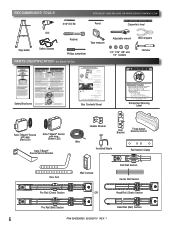
... Header Bracket Safe-T-Beam® Source with wire (Red LED) Safe-T-Beam® Sensor with wire (Green LED) Wire Door Bracket Three-button Remote Control Safe-T-Beam® Source/Sensor Bracket Insulated Staple Rail Section Clamp Door Arm Wall Console End Rail Section Center Rail Section Pro Rail (Chain) Section OR Head Rail (Chain) Section Pro Rail (Belt) Section Head Rail (Belt) Section 6 PN# 3642036534, 02/26/2010 REV. 1 RECOMMENDED TOOLS FOR HELP-1.800.354.3643 OR WWW.GENIECOMPANY.COM 3/16" Drill Bit Pencil Carpenter's level Drill Step ladder Safety...
... Header Bracket Safe-T-Beam® Source with wire (Red LED) Safe-T-Beam® Sensor with wire (Green LED) Wire Door Bracket Three-button Remote Control Safe-T-Beam® Source/Sensor Bracket Insulated Staple Rail Section Clamp Door Arm Wall Console End Rail Section Center Rail Section Pro Rail (Chain) Section OR Head Rail (Chain) Section Pro Rail (Belt) Section Head Rail (Belt) Section 6 PN# 3642036534, 02/26/2010 REV. 1 RECOMMENDED TOOLS FOR HELP-1.800.354.3643 OR WWW.GENIECOMPANY.COM 3/16" Drill Bit Pencil Carpenter's level Drill Step ladder Safety...

Owner's Manual
Page 7
... SCREW - 5/16'' x 2'' 4 SELF DRILLING SCREW - 1/4''-20 x 3/4'' DOOR BRACKET 5 HEX BOLT - 5/16''-18 x 3/4'' SELF LOCKING NUT - 5/16''-18 HEX FLANGE NUT - 5/16''-18 CLEVIS PIN - 5/16" x 3/4" COTTER PIN 6 WALL CONSOLE ASSEMBLY PAN HEAD PHILLIPS SCREW - #4-24 x 1'' 7 13 MM INSULATED STAPLE 8 Safe-T-Beam® SOURCE/SENSOR BRACKET PHILLIPS HEX SCREW - #10-16 x 1- 1/4'' WIRE NUT (GREY) NO NUMBER REMOTE WITH BATTERY NO BAG Safe-T-Beam® SOURCE/SENSOR & WIRE SET NO NUMBER LIGHT COVER - FASTENERS - COLOR QUANTITY 2 8 8 3 1 1 1 2 5 5 2 3 1 3 1 2 1 1 1 2 30 2 4 4 1 1 1 1 Rail...
... SCREW - 5/16'' x 2'' 4 SELF DRILLING SCREW - 1/4''-20 x 3/4'' DOOR BRACKET 5 HEX BOLT - 5/16''-18 x 3/4'' SELF LOCKING NUT - 5/16''-18 HEX FLANGE NUT - 5/16''-18 CLEVIS PIN - 5/16" x 3/4" COTTER PIN 6 WALL CONSOLE ASSEMBLY PAN HEAD PHILLIPS SCREW - #4-24 x 1'' 7 13 MM INSULATED STAPLE 8 Safe-T-Beam® SOURCE/SENSOR BRACKET PHILLIPS HEX SCREW - #10-16 x 1- 1/4'' WIRE NUT (GREY) NO NUMBER REMOTE WITH BATTERY NO BAG Safe-T-Beam® SOURCE/SENSOR & WIRE SET NO NUMBER LIGHT COVER - FASTENERS - COLOR QUANTITY 2 8 8 3 1 1 1 2 5 5 2 3 1 3 1 2 1 1 1 2 30 2 4 4 1 1 1 1 Rail...
Owner's Manual
Page 9
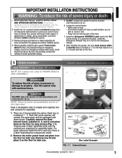
... locks connected to POWER HEAD & RAIL ASSEMBLY. Install the Entrapment WARNING Label next to cables, spring assemblies, and other hardware before installing opener. 4. CAUTION Do NOT run until instructed to avoid accidental release. 5. For quick reference inside the carton. Locate the control button: ‡ Within sight of door, ‡ At minimum height of the door. 7. Remove the motor power head and place it on the floor for later use . Have a trained door...
... locks connected to POWER HEAD & RAIL ASSEMBLY. Install the Entrapment WARNING Label next to cables, spring assemblies, and other hardware before installing opener. 4. CAUTION Do NOT run until instructed to avoid accidental release. 5. For quick reference inside the carton. Locate the control button: ‡ Within sight of door, ‡ At minimum height of the door. 7. Remove the motor power head and place it on the floor for later use . Have a trained door...

Owner's Manual
Page 11
... installation (Fig. 1-8). Power head assembly. Remove Remove FIG. 1-8 Disable garage door lock. Drive chain can slide out of rail assembly T-Rail FIG. 1-7 Belt adjustment. Tighten the chain by aligning the sprocket onto the motor shaft. Do NOT over tighten belt. If you have removed all ropes and/or cables (NOT door lift cables) and disabled the door lock already. The belt adjustment nut is approximately 1/8 inch above the base of the rail at center of rail) Use 1/2" socket on the rail...
... installation (Fig. 1-8). Power head assembly. Remove Remove FIG. 1-8 Disable garage door lock. Drive chain can slide out of rail assembly T-Rail FIG. 1-7 Belt adjustment. Tighten the chain by aligning the sprocket onto the motor shaft. Do NOT over tighten belt. If you have removed all ropes and/or cables (NOT door lift cables) and disabled the door lock already. The belt adjustment nut is approximately 1/8 inch above the base of the rail at center of rail) Use 1/2" socket on the rail...

Owner's Manual
Page 13
... provided) to ceiling using clevis pin and cotter pin (Fig. 2-5). • Support power head on wall next to ceiling, insure that rail clamp bolts and nuts are tight. • DO NOT PLUG OPENER IN YET! (Chain drive shown) FIG. 2-5 Rail mounting to following (Fig. 2-6). Getting started. • Position assembled rail on step-ladder to scale) NOTE: For header bracket pins locate Bag 2 from Box 1. 2. Ensure door does not contact any...
... provided) to ceiling using clevis pin and cotter pin (Fig. 2-5). • Support power head on wall next to ceiling, insure that rail clamp bolts and nuts are tight. • DO NOT PLUG OPENER IN YET! (Chain drive shown) FIG. 2-5 Rail mounting to following (Fig. 2-6). Getting started. • Position assembled rail on step-ladder to scale) NOTE: For header bracket pins locate Bag 2 from Box 1. 2. Ensure door does not contact any...
Owner's Manual
Page 15
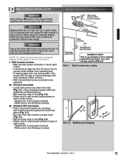
... wires can cause the door to operate unexpectedly and the light not to wall console board screws on back of wall console. - When using the guidelines mentioned above .) ‡ Split and strip ends of wire (Fig. 3-2). ‡ Fasten wire to work. NOTE: For Wall Console,wire and insulated staples locate Bags 6 and 7 from power head to control board screws on back of wall console. - Wall console Separate entry door "Entrapment" warning label EXAMPLE ONLY! Wiring (If pre-wired). ‡ Locate wall console pre-wired wire...
... wires can cause the door to operate unexpectedly and the light not to wall console board screws on back of wall console. - When using the guidelines mentioned above .) ‡ Split and strip ends of wire (Fig. 3-2). ‡ Fasten wire to work. NOTE: For Wall Console,wire and insulated staples locate Bags 6 and 7 from power head to control board screws on back of wall console. - Wall console Separate entry door "Entrapment" warning label EXAMPLE ONLY! Wiring (If pre-wired). ‡ Locate wall console pre-wired wire...

Owner's Manual
Page 16
... this manual. - Mounting. ‡ Fasten wall console to wall with 2 screws (provided) (Fig. 3-4). ‡ Remove protective backing from inside garage 3 Independent Light Control - Vacation Locking Switch - The "Entrapment" label is located in the orange locking clips above each terminal hole. (You can use a pencil or small screwdriver to power head, Insulated Staple remove it. ‡ On power head: - Controls door opener lights from "Entrapment" warning label (Fig. 3-5). Locking Clips Terminal Holes 6 54 321 wire guide...
... this manual. - Mounting. ‡ Fasten wall console to wall with 2 screws (provided) (Fig. 3-4). ‡ Remove protective backing from inside garage 3 Independent Light Control - Vacation Locking Switch - The "Entrapment" label is located in the orange locking clips above each terminal hole. (You can use a pencil or small screwdriver to power head, Insulated Staple remove it. ‡ On power head: - Controls door opener lights from "Entrapment" warning label (Fig. 3-5). Locking Clips Terminal Holes 6 54 321 wire guide...
Owner's Manual
Page 17
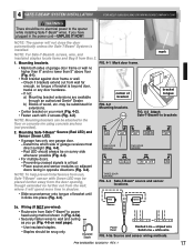
... side whenever possible (Fig. 4-4). ‡ For multiple doors. - SUN bracket tongue FIG. 4-3 Attach Safe-T-Beam® to the opener while installing Safe-T-Beam® wires. ckets RED LED GREEN LED GREEN LED RED RED LED LED GREEN LED ONE DOOR GARAGE TWO DOOR GARAGE GREEN LED RED RED LED LED GREEN GREEN LED LED RED LED THREE DOOR GARAGE FIG. 4-4 Safe-T-Beam® source and sensor locations. Red LED should always be on adjacent doors facing in (Fig. 4-5a). ‡ Securely fasten wires to the floor or concrete rim using method shown in opposite directions (Fig. 4-4). 4 AFE...
... side whenever possible (Fig. 4-4). ‡ For multiple doors. - SUN bracket tongue FIG. 4-3 Attach Safe-T-Beam® to the opener while installing Safe-T-Beam® wires. ckets RED LED GREEN LED GREEN LED RED RED LED LED GREEN LED ONE DOOR GARAGE TWO DOOR GARAGE GREEN LED RED RED LED LED GREEN GREEN LED LED RED LED THREE DOOR GARAGE FIG. 4-4 Safe-T-Beam® source and sensor locations. Red LED should always be on adjacent doors facing in (Fig. 4-5a). ‡ Securely fasten wires to the floor or concrete rim using method shown in opposite directions (Fig. 4-4). 4 AFE...

Owner's Manual
Page 19
... generator. WITH GROUNDED PLUG: Plug the opener into a properly grounded electrical outlet (Fig. 5-1). This product is designed to make sure that no part of door or its movement will not close " button on the wall control during the closing , if Safe-T-Beam® is a misalignment. White to white/black to black/ground to power. Use the adjustment screw located on motor must be at the Green LED sensor. DO NOT alter the...
... generator. WITH GROUNDED PLUG: Plug the opener into a properly grounded electrical outlet (Fig. 5-1). This product is designed to make sure that no part of door or its movement will not close " button on the wall control during the closing , if Safe-T-Beam® is a misalignment. White to white/black to black/ground to power. Use the adjustment screw located on motor must be at the Green LED sensor. DO NOT alter the...

Owner's Manual
Page 20
...Carriage Assembly Belt Connector Latch Movement FIG. 6-2 Engage Chain/Belt Connector to Carriage. Door is fully closed. 2. The LED indicator light will blink green once. LED Indicator Light Open Open Set Limit Travel Limit Button Up Force OPEN Control Adjustment To Garage Door SET LEARN MANUAL LIMIT FORCE SET Learn Code CODE Button Close Travel Limit Close CLOSE Down Force Set Limit Control Button Adjustment FIG. 6-1 Limit controls. Press and hold the "Close Travel Limit" button until the door is fully closed position in the UP direction. 2. You can also use...
...Carriage Assembly Belt Connector Latch Movement FIG. 6-2 Engage Chain/Belt Connector to Carriage. Door is fully closed. 2. The LED indicator light will blink green once. LED Indicator Light Open Open Set Limit Travel Limit Button Up Force OPEN Control Adjustment To Garage Door SET LEARN MANUAL LIMIT FORCE SET Learn Code CODE Button Close Travel Limit Close CLOSE Down Force Set Limit Control Button Adjustment FIG. 6-1 Limit controls. Press and hold the "Close Travel Limit" button until the door is fully closed position in the UP direction. 2. You can also use...
Owner's Manual
Page 22
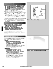
... force adjustments and limit switch settings MUST BE COMPLETED before hitting board. - FIG. 6-6 2 x 4 under center of garage door opening . 22 PN# 3642036534, 02/26/2010 REV. 1 By turning the Open Force Control clockwise, the OPEN force can be increased. Set the OPEN force level at the minimum force required to see if door has "close and open door without reversing. 2. All close " limit programmed. Testing. ‡ Open garage door using wall button. ‡ When door contacts board, the door must stop (within 2 seconds) and reverse direction returning to open travel limits...
... force adjustments and limit switch settings MUST BE COMPLETED before hitting board. - FIG. 6-6 2 x 4 under center of garage door opening . 22 PN# 3642036534, 02/26/2010 REV. 1 By turning the Open Force Control clockwise, the OPEN force can be increased. Set the OPEN force level at the minimum force required to see if door has "close and open door without reversing. 2. All close " limit programmed. Testing. ‡ Open garage door using wall button. ‡ When door contacts board, the door must stop (within 2 seconds) and reverse direction returning to open travel limits...

Owner's Manual
Page 23
... not been reprogrammed. Door will stop . ‡ Press button again. - This equipment generates, uses and can learn code button (on a circuit different from the moving door and its parts. However, there is now programmed and ready for 10 seconds or until the red blinking indicator LED goes out. ‡ Program remaining or new remote controls as done previously. LED Indicator Light Open Open Set Limit Travel Limit Button Up Force OPEN Control Adjustment To Garage Door SET LOST OR STOLEN REMOTE LEARN MANUAL LIMIT FORCE 1. FIG. 7-1 Learn code button and LED PN# 3642036534...
... not been reprogrammed. Door will stop . ‡ Press button again. - This equipment generates, uses and can learn code button (on a circuit different from the moving door and its parts. However, there is now programmed and ready for 10 seconds or until the red blinking indicator LED goes out. ‡ Program remaining or new remote controls as done previously. LED Indicator Light Open Open Set Limit Travel Limit Button Up Force OPEN Control Adjustment To Garage Door SET LOST OR STOLEN REMOTE LEARN MANUAL LIMIT FORCE 1. FIG. 7-1 Learn code button and LED PN# 3642036534...

Owner's Manual
Page 25
... closed , pull emergency release knob (Carriage Lock) towards door to adjust the opener properly may cause severe injury or death. 6. If you have any hardware, and DO NOT OPERATE garage door automatically or manually if door is improperly balanced or springs are under extreme pressure and tension. • DO NOT attempt to carriage assembly. • Red LED blinks. - See your garage door Owner's Manual. READ AND FOLLOW ALL INSTRUCTIONS. 2. Door will re-attach itself to repair...
... closed , pull emergency release knob (Carriage Lock) towards door to adjust the opener properly may cause severe injury or death. 6. If you have any hardware, and DO NOT OPERATE garage door automatically or manually if door is improperly balanced or springs are under extreme pressure and tension. • DO NOT attempt to carriage assembly. • Red LED blinks. - See your garage door Owner's Manual. READ AND FOLLOW ALL INSTRUCTIONS. 2. Door will re-attach itself to repair...
Owner's Manual
Page 27
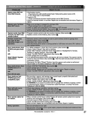
... sure chain/belt is OK. - If lamp works, power source is flashing. ‡ Check Safe-T-Beam® system for no operation. Remote control has less than 30 seconds each way if door does not move . ‡ Make sure carriage is closed . Hold the wall console down until door is being pushed or LED does not come ON - Repair or replace. Door opener will only run closed . Realign or replace Sensors. (See section 3 ) ‡ Check "CLOSE FORCE" adjustment (See...
... sure chain/belt is OK. - If lamp works, power source is flashing. ‡ Check Safe-T-Beam® system for no operation. Remote control has less than 30 seconds each way if door does not move . ‡ Make sure carriage is closed . Hold the wall console down until door is being pushed or LED does not come ON - Repair or replace. Door opener will only run closed . Realign or replace Sensors. (See section 3 ) ‡ Check "CLOSE FORCE" adjustment (See...

Owner's Manual
Page 28
... ‡ Wire to power head or wire connection at 1-800-35-GENIE ‡ Contact Genie® authorized dealer for obstruction Safe-T-Beam® sensor ‡ Limits set backwards ‡ Clear limits and reprogram (See section 6 ) ‡ Wall console wire short ‡ Wall console wires reversed in power head connector. (See section 3 ) ‡ Chain/belt is bad. ‡ Set UP LIMIT programming ‡ Check power head wiring, check connections, - NOTE: The 5 BLINKS pattern will remain blinking until Thermal Protector cools and resets. Check door spring -
... ‡ Wire to power head or wire connection at 1-800-35-GENIE ‡ Contact Genie® authorized dealer for obstruction Safe-T-Beam® sensor ‡ Limits set backwards ‡ Clear limits and reprogram (See section 6 ) ‡ Wall console wire short ‡ Wall console wires reversed in power head connector. (See section 3 ) ‡ Chain/belt is bad. ‡ Set UP LIMIT programming ‡ Check power head wiring, check connections, - NOTE: The 5 BLINKS pattern will remain blinking until Thermal Protector cools and resets. Check door spring -

Owner's Manual
Page 30
... other cause beyond the reasonable control of Seller, and does not cover batteries, missing or damaged parts from clearance or open box sales, or repairs or maintenance to door components ALL EXPRESS AND IMPLIED WARRANTIES FOR THE PRODUCT, INCLUDING BUT NOT LIMITED TO ANY IMPLIED WARRANTIES OF MERCHANTABILITY AND FITNESS FOR A PARTICULAR PURPOSE, ARE LIMITED IN TIME TO THE APPLICABLE WARRANTY PERIOD...
... other cause beyond the reasonable control of Seller, and does not cover batteries, missing or damaged parts from clearance or open box sales, or repairs or maintenance to door components ALL EXPRESS AND IMPLIED WARRANTIES FOR THE PRODUCT, INCLUDING BUT NOT LIMITED TO ANY IMPLIED WARRANTIES OF MERCHANTABILITY AND FITNESS FOR A PARTICULAR PURPOSE, ARE LIMITED IN TIME TO THE APPLICABLE WARRANTY PERIOD...


