
Manual
Page 2
... Diagram ...4 Chapter 1 Hardware Installation 5 1-1 Considerations Prior to Installation 5 1-2 Feature Summary 6 1-3 Installation of Memory 7 1-4 Installation of Expansion Cards 8 1-5 I/O Back Panel Introduction 9 1-6 Connectors Introduction 10 Chapter 2 BIOS Setup 19 The Main Menu (For example: BIOS Ver. : F2e 20 2-1 Standard CMOS Features 22 2-2 Advanced BIOS Features 24 2-3 Advanced Chipset Features 27 2-4 IntegratedPeripherals 30 2-5 Power Management Setup 34 2-6 PnP/PCI Configurations 37 2-7 PC Health Status 38 2-8 Frequency/Voltage Control 39 2-9 Load Fail-Safe Defaults...
... Diagram ...4 Chapter 1 Hardware Installation 5 1-1 Considerations Prior to Installation 5 1-2 Feature Summary 6 1-3 Installation of Memory 7 1-4 Installation of Expansion Cards 8 1-5 I/O Back Panel Introduction 9 1-6 Connectors Introduction 10 Chapter 2 BIOS Setup 19 The Main Menu (For example: BIOS Ver. : F2e 20 2-1 Standard CMOS Features 22 2-2 Advanced BIOS Features 24 2-3 Advanced Chipset Features 27 2-4 IntegratedPeripherals 30 2-5 Power Management Setup 34 2-6 PnP/PCI Configurations 37 2-7 PC Health Status 38 2-8 Frequency/Voltage Control 39 2-9 Load Fail-Safe Defaults...
Manual
Page 5
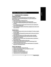
... all cables and power connectors are no leftover screws or metal components placed on the motherboard or within a electrostatic shielding container. 5. Installation Notices 1. Before using the product, please verify that the power supply is best to wear an electrostatic discharge (ESD) cuff when handling electronic components (CPU, RAM). 4. Please make sure there are connected. 4. Damage due to installation, please follow the instructions below...
... all cables and power connectors are no leftover screws or metal components placed on the motherboard or within a electrostatic shielding container. 5. Installation Notices 1. Before using the product, please verify that the power supply is best to wear an electrostatic discharge (ESD) cuff when handling electronic components (CPU, RAM). 4. Please make sure there are connected. 4. Damage due to installation, please follow the instructions below...

Manual
Page 6
... AWARD BIOS Form Factor Mini-ITX form factor; 17.0cm x 17.0cm GA-7CN700ID Motherboard - 6 - Supports data striping (RAID 0), mirroring (RAID 1) for Serial ATA O.S Support Microsoft Windows 2000/XP Memory 1 DDRII DIMM memory slots Supports 1.8V DDRII DIMMs Expanstion Slots 1 PCI slot Internal Connectors 1 20-pin ATX power connector 2 IDE connectors 2 SATA connectors 1 system fan connector 1 front panel connector 1 front audio connector 1 CD In connector 2 USB...
... AWARD BIOS Form Factor Mini-ITX form factor; 17.0cm x 17.0cm GA-7CN700ID Motherboard - 6 - Supports data striping (RAID 0), mirroring (RAID 1) for Serial ATA O.S Support Microsoft Windows 2000/XP Memory 1 DDRII DIMM memory slots Supports 1.8V DDRII DIMMs Expanstion Slots 1 PCI slot Internal Connectors 1 20-pin ATX power connector 2 IDE connectors 2 SATA connectors 1 system fan connector 1 front panel connector 1 front audio connector 1 CD In connector 2 USB...

Manual
Page 12
... settings, please refer to work properly. Pin No. Before attaching the IDE cable, please take note of the foolproof groove in order to the instructions located on the IDE device). Definition 1 GND 7 1 2 TXP 3 TXN 4 GND 5 RXN 6 RXP 7 GND GA-7CN700ID Motherboard - 12 - One IDE connector can connect to one IDE device as Master and the other as Slave (for the Serial ATA and install the proper driver in the IDE connector...
... settings, please refer to work properly. Pin No. Before attaching the IDE cable, please take note of the foolproof groove in order to the instructions located on the IDE device). Definition 1 GND 7 1 2 TXP 3 TXN 4 GND 5 RXN 6 RXP 7 GND GA-7CN700ID Motherboard - 12 - One IDE connector can connect to one IDE device as Master and the other as Slave (for the Serial ATA and install the proper driver in the IDE connector...
Manual
Page 13
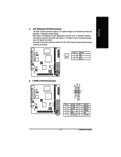
... Fan Power Connector) The cooler fan power connector supplies a +12V power voltage via a 3-pin power connector and possesses a foolproof connection design. HD_LED+ 2 HD_LED- 4 GND 6 RESET 8 ACT_LED+ 10 Definition MSGLED+ MSGLEDPWRSW GND ACT_LED- - 13 - Hardware Installation Remember to connect the System fan cable to the SYS_FAN connector to prevent system hanging caused by overheating. 1 SYS_FAN Pin No. 1 2 3 Definition GND +12V Sense 5) F_PANEL (Front Panel Connector) MSG+ MSG- A red power connector wire indicates a positive connection and requires a +12V power voltage...
... Fan Power Connector) The cooler fan power connector supplies a +12V power voltage via a 3-pin power connector and possesses a foolproof connection design. HD_LED+ 2 HD_LED- 4 GND 6 RESET 8 ACT_LED+ 10 Definition MSGLED+ MSGLEDPWRSW GND ACT_LED- - 13 - Hardware Installation Remember to connect the System fan cable to the SYS_FAN connector to prevent system hanging caused by overheating. 1 SYS_FAN Pin No. 1 2 3 Definition GND +12V Sense 5) F_PANEL (Front Panel Connector) MSG+ MSG- A red power connector wire indicates a positive connection and requires a +12V power voltage...

Manual
Page 16
... the manufacturer's instructions. Open: Normal Short: Clear CMOS GA-7CN700ID Motherboard - 16 - Gently take out the battery and put it aside for five seconds.) 3. To clear CMOS, temporarily short the two pins. Plug the power cord in the battery holder to its default values by the manufacturer. If you can use of explosion if battery is incorrectly replaced. Re-install the battery. 4. English 10) BAT (Battery) Danger of this header. Replace only with...
... the manufacturer's instructions. Open: Normal Short: Clear CMOS GA-7CN700ID Motherboard - 16 - Gently take out the battery and put it aside for five seconds.) 3. To clear CMOS, temporarily short the two pins. Plug the power cord in the battery holder to its default values by the manufacturer. If you can use of explosion if battery is incorrectly replaced. Re-install the battery. 4. English 10) BAT (Battery) Danger of this header. Replace only with...
Manual
Page 19
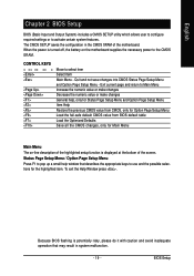
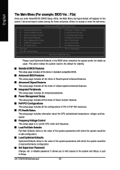
... for Main Menu Main Menu The on the motherboard supplies the necessary power to pop up a small help , only for Status Page Setup Menu and Option Page Setup Menu Item Help Restore the previous CMOS value from CMOS, only for Option Page Setup Menu Load the fail-safe default CMOS value from BIOS default table Load the Optimized Defaults Save all the CMOS changes, only for the highlighted item. Status Page Setup Menu / Option Page Setup Menu Press F1 to the CMOS SRAM. BIOS Setup CONTROL KEYS Enter...
... for Main Menu Main Menu The on the motherboard supplies the necessary power to pop up a small help , only for Status Page Setup Menu and Option Page Setup Menu Item Help Restore the previous CMOS value from CMOS, only for Option Page Setup Menu Load the fail-safe default CMOS value from BIOS default table Load the Optimized Defaults Save all the CMOS changes, only for the highlighted item. Status Page Setup Menu / Option Page Setup Menu Press F1 to the CMOS SRAM. BIOS Setup CONTROL KEYS Enter...
Manual
Page 20
... temperature, voltage, and fan, speed. Frequency/Voltage Control This setup page is to control CPU clock and frequency. Load Fail-Safe Defaults Fail-Safe Defaults refers to the value of the system parameters with which the system would be in the BIOS when somehow the system works not stable as figure below) will appear on the screen. It allows you enter Award BIOS CMOS Setup Utility, the Main Menu (as usual. GA-7CN700ID Motherboard - 20 - Phoenix-Award BIOS CMOS Setup Utility Standard CMOS...
... temperature, voltage, and fan, speed. Frequency/Voltage Control This setup page is to control CPU clock and frequency. Load Fail-Safe Defaults Fail-Safe Defaults refers to the value of the system parameters with which the system would be in the BIOS when somehow the system works not stable as figure below) will appear on the screen. It allows you enter Award BIOS CMOS Setup Utility, the Main Menu (as usual. GA-7CN700ID Motherboard - 20 - Phoenix-Award BIOS CMOS Setup Utility Standard CMOS...

Manual
Page 22
... if no IDE devices are : Large/Auto(default:Auto) GA-7CN700ID Motherboard - 22 - to Sat. You can use one of the two methods: Auto Allows BIOS to automatically detect IDE devices during POST. (Default value) None Select this if no IDE devices are : CHS/LBA/Large/Auto (Default:Auto) IDE Channel 2/3 Master IDE HDD Auto-Detection Press "Enter" to Sat., is calculated based on the 24-hour military-time clock. to select this option for the hard drive. Day...
... if no IDE devices are : Large/Auto(default:Auto) GA-7CN700ID Motherboard - 22 - to Sat. You can use one of the two methods: Auto Allows BIOS to automatically detect IDE devices during POST. (Default value) None Select this if no IDE devices are : CHS/LBA/Large/Auto (Default:Auto) IDE Channel 2/3 Master IDE HDD Auto-Detection Press "Enter" to Sat., is calculated based on the 24-hour military-time clock. to select this option for the hard drive. Day...
Manual
Page 23
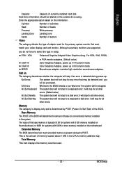
... Disk/Key The system boot will not stop for a keyboard or disk error; BIOS Setup The value of memory located above 1 MB in the system. This is the amount of the base memory is determined by POST (Power On Self Test) of currently installed hard disk. Hard drive information should be stopped. Base Memory The POST of the BIOS will not stop for all other errors. Total Memory This item displays the memory size that used for...
... Disk/Key The system boot will not stop for a keyboard or disk error; BIOS Setup The value of memory located above 1 MB in the system. This is the amount of the base memory is determined by POST (Power On Self Test) of currently installed hard disk. Hard drive information should be stopped. Base Memory The POST of the BIOS will not stop for all other errors. Total Memory This item displays the memory size that used for...
Manual
Page 24
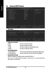
... Monitor Bus VID +/-/PU/PD: Value F10: Save F6: Fail-Safe Defaults ESC: Exit F1: General Help F7: Optimized Defaults Phoenix- English 2-2 Advanced BIOS Features CPU Feature Hard Disk Boot Priority Virus Warning BIOS Flash Protection Quick Power On Self Test First Boot Device Second Boot Device Third Boot Device Boot Other Device Boot Up Num Lock Status Security Option Video BIOS Shadow Phoenix-Award BIOS CMOS Setup Utility Advanced BIOS Features [Press Enter] [Press Enter] [Disabled] [Auto] [Enabled] [Hard Disk] [USB-FDD] [CDROM] [Enabled] [On] [Setup] [Enabled...
... Monitor Bus VID +/-/PU/PD: Value F10: Save F6: Fail-Safe Defaults ESC: Exit F1: General Help F7: Optimized Defaults Phoenix- English 2-2 Advanced BIOS Features CPU Feature Hard Disk Boot Priority Virus Warning BIOS Flash Protection Quick Power On Self Test First Boot Device Second Boot Device Third Boot Device Boot Other Device Boot Up Num Lock Status Security Option Video BIOS Shadow Phoenix-Award BIOS CMOS Setup Utility Advanced BIOS Features [Press Enter] [Press Enter] [Disabled] [Auto] [Enabled] [Hard Disk] [USB-FDD] [CDROM] [Enabled] [On] [Setup] [Enabled...
Manual
Page 25
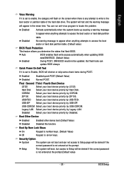
... Legacy LAN. Hard Disk Select your boot device priority by Disabled. Legacy LAN Select your boot device priority by USB-FDD. Security Option System The system can not boot and can not access to Setup page will be denied if the correct password is not entered at the prompt. You can update BIOS always. Setup The system will boot, but access to Setup will be denied if the correct password is not entered at the prompt.(Default...
... Legacy LAN. Hard Disk Select your boot device priority by Disabled. Legacy LAN Select your boot device priority by USB-FDD. Security Option System The system can not boot and can not access to Setup page will be denied if the correct password is not entered at the prompt. You can update BIOS always. Setup The system will boot, but access to Setup will be denied if the correct password is not entered at the prompt.(Default...
Manual
Page 28
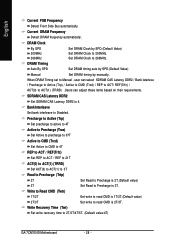
... is 2T/3T. DRAM Timing Auto By SPD Set DRAM timing auto by SPD.(Default Value) Manual Set DRAM timing by SPD.(Default Value) 200MHz 266MHz Set DRAM Clock to 200MHz. Write Recovery Time (Twr) Set write recovery time to Precharge is 4. SDRAM CAS Latency DDR2 Set SDRAM CAS Latency DDR2 is 3T. DRAM Clock By SPD Set DRAM Clock by manually. English Current FSB Frequency Detect Front Side Bus automatically. Current DRAM Frequency Detect DRAM fruquency automatically.
... is 2T/3T. DRAM Timing Auto By SPD Set DRAM timing auto by SPD.(Default Value) Manual Set DRAM timing by SPD.(Default Value) 200MHz 266MHz Set DRAM Clock to 200MHz. Write Recovery Time (Twr) Set write recovery time to Precharge is 4. SDRAM CAS Latency DDR2 Set SDRAM CAS Latency DDR2 is 3T. DRAM Clock By SPD Set DRAM Clock by manually. English Current FSB Frequency Detect Front Side Bus automatically. Current DRAM Frequency Detect DRAM fruquency automatically.
Manual
Page 29
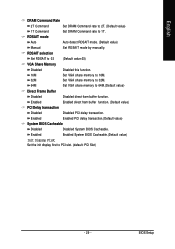
...Set DRAM Command rate to 32M. BIOS Setup Set VGA share memory to 1T. Enabled Enabled System BIOS Cacheable.(Default value) Init Display First Set the init display first to 03 (Default value:03) VGA Share Memory Disabled 16M 32M 64M Disabled this function. Enabled Enabled direct fram buffer function. (Default value) PCI Delay transaction Disabled Disabled PCI delay transaction. RDSAIT selection Set RDSAIT to PCI slot. (default: PCI Slot) - 29 - RDSAIT mode Auto Auto detect RDSAIT mode. (Default value) Manual Set RDSAIT mode by manually. Enabled Enabled PCI...
...Set DRAM Command rate to 32M. BIOS Setup Set VGA share memory to 1T. Enabled Enabled System BIOS Cacheable.(Default value) Init Display First Set the init display first to 03 (Default value:03) VGA Share Memory Disabled 16M 32M 64M Disabled this function. Enabled Enabled direct fram buffer function. (Default value) PCI Delay transaction Disabled Disabled PCI delay transaction. RDSAIT selection Set RDSAIT to PCI slot. (default: PCI Slot) - 29 - RDSAIT mode Auto Auto detect RDSAIT mode. (Default value) Manual Set RDSAIT mode by manually. Enabled Enabled PCI...
Manual
Page 31
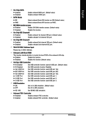
... onboard 2nd channel IDE port. BIOS Setup Onboard LAN Boot ROM This function decide whether to USB emulation. On-Chip IDE Channel0 Enabled Enable onboard 1st channel IDE port. (Default value) Disabled Disable onboard 1st channel IDE port. VIA-6102 MAC Address Input Please key in MAC Address. Enabled Enable onboard FDC controller. (Default value) - 31 - English On-Chip SATA Enabled Disabled Enable onboard SATA port. (Default value) Disable onboard SATA port. Enabled Enable this function. SATA Mode IDE Select onboard Seria ATA function as IDE.(Default value) RAID...
... onboard 2nd channel IDE port. BIOS Setup Onboard LAN Boot ROM This function decide whether to USB emulation. On-Chip IDE Channel0 Enabled Enable onboard 1st channel IDE port. (Default value) Disabled Disable onboard 1st channel IDE port. VIA-6102 MAC Address Input Please key in MAC Address. Enabled Enable onboard FDC controller. (Default value) - 31 - English On-Chip SATA Enabled Disabled Enable onboard SATA port. (Default value) Disable onboard SATA port. Enabled Enable this function. SATA Mode IDE Select onboard Seria ATA function as IDE.(Default value) RAID...

Manual
Page 34
...) IRQ12 (PS/2 Mouse) IRQ13 (Coprocessor) IRQ14 (Hard Disk) IRQ15 (Reserved) [ON] [Disabled] [Enabled] [Enabled] [Enabled] [Enabled] [Disabled] [Disabled] [Disabled] [Disabled] [Enabled] [Enabled] [Enabled] [Disabled] Item Help Menu Level Move Enter: Select F5: Previous Values +/-/PU/PD: Value F10: Save F6: Fail-Safe Defaults ESC: Exit F1: General Help F7: Optimized Defaults GA-7CN700ID Motherboard - 34 - English 2-5 Power Management Setup ACPI function ACPI Suspend Type Modem Use IRQ Soft-Off by PCI Card Modem Ring Resume RTC Alarm Resume x Date...
...) IRQ12 (PS/2 Mouse) IRQ13 (Coprocessor) IRQ14 (Hard Disk) IRQ15 (Reserved) [ON] [Disabled] [Enabled] [Enabled] [Enabled] [Enabled] [Disabled] [Disabled] [Disabled] [Disabled] [Enabled] [Enabled] [Enabled] [Disabled] Item Help Menu Level Move Enter: Select F5: Previous Values +/-/PU/PD: Value F10: Save F6: Fail-Safe Defaults ESC: Exit F1: General Help F7: Optimized Defaults GA-7CN700ID Motherboard - 34 - English 2-5 Power Management Setup ACPI function ACPI Suspend Type Modem Use IRQ Soft-Off by PCI Card Modem Ring Resume RTC Alarm Resume x Date...
Manual
Page 36
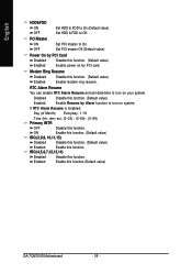
... OFF Disable this function.(Default value) GA-7CN700ID Motherboard - 36 - IRQ (4,5,6,7,12,13,14) Disabled Enabled Disable this function. PCI Master ON Set PCI master to turn on your system. OFF Set PCI master Off (Default value) Power On by PCI Card Disabled Disable this function. (Default value) Enabled Enable modem ring resume. ON Enable this function. (Default value) IRQ (3,8,9, 10,11,15) Disabled Disable this function. (Default value) Enabled Enable this function. Modem Ring Resume Disabled Disable this function. (Default value) Enabled Enable power...
... OFF Disable this function.(Default value) GA-7CN700ID Motherboard - 36 - IRQ (4,5,6,7,12,13,14) Disabled Enabled Disable this function. PCI Master ON Set PCI master to turn on your system. OFF Set PCI master Off (Default value) Power On by PCI Card Disabled Disable this function. (Default value) Enabled Enable modem ring resume. ON Enable this function. (Default value) IRQ (3,8,9, 10,11,15) Disabled Disable this function. (Default value) Enabled Enable this function. Modem Ring Resume Disabled Disable this function. (Default value) Enabled Enable power...
Manual
Page 37
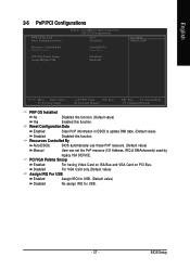
BIOS Setup Disabled For VGA Card only.(Default value) Assign IRQ For USB Enabled Assign IRQ for USB. (Default value) Disabled No assign IRQ for USB. - 37 - Resources Controlled By Auto(ESCD) BIOS automatically use these PnP rescuers. (Default value) Manual User can set the PnP resource (I/O Address, IRQ & DMAchannels) used by legacy ISA DEVICE. AwardBIOS CMOS Setup Utility PnP / PCI Configurations [No] [Disabled] Resources Controlled By x IRQ Resources [Auto(ESCD)] Press Enter PCI/VGA Palette Snoop Assign IRQ For USB [Disabled] [Enabled] Item Help Menu Level&#...
BIOS Setup Disabled For VGA Card only.(Default value) Assign IRQ For USB Enabled Assign IRQ for USB. (Default value) Disabled No assign IRQ for USB. - 37 - Resources Controlled By Auto(ESCD) BIOS automatically use these PnP rescuers. (Default value) Manual User can set the PnP resource (I/O Address, IRQ & DMAchannels) used by legacy ISA DEVICE. AwardBIOS CMOS Setup Utility PnP / PCI Configurations [No] [Disabled] Resources Controlled By x IRQ Resources [Auto(ESCD)] Press Enter PCI/VGA Palette Snoop Assign IRQ For USB [Disabled] [Enabled] Item Help Menu Level&#...
Manual
Page 40
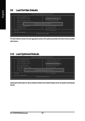
...Optimized Defaults Phoenix-Award BIOS CMOS Setup Utility Standard CMOS Features Advanced BIOS Features Advanced Chipset Features Integrated Peripherals Power Management Setup PnP/PCI Configurations PC Health Status Esc: Quit F10: Save & Exit Setup Frequency/Voltage control Load Fail-Safe Defaults Load Optimized Defaults Set Supervisor Password Set User Password Save & Exit Setup Load Optimized DefaEuxltist W(Yi/tNho)?utNSaving Select Item Load Optimized Defaults Selecting this field loads the factory defaults for BIOS...
...Optimized Defaults Phoenix-Award BIOS CMOS Setup Utility Standard CMOS Features Advanced BIOS Features Advanced Chipset Features Integrated Peripherals Power Management Setup PnP/PCI Configurations PC Health Status Esc: Quit F10: Save & Exit Setup Frequency/Voltage control Load Fail-Safe Defaults Load Optimized Defaults Set Supervisor Password Set User Password Save & Exit Setup Load Optimized DefaEuxltist W(Yi/tNho)?utNSaving Select Item Load Optimized Defaults Selecting this field loads the factory defaults for BIOS...

Manual
Page 41
English 2-11 Set Supervisor/User Password Phoenix-Award BIOS CMOS Setup Utility Standard CMOS Features Advanced BIOS Features Advanced Chipset Features Integrated Peripherals Power Management Setup PnP/PCI Configurations PC Health Status Enter Password: Frequency/Voltage control Load Fail-Safe Defaults Load Optimized Defaults Set Supervisor Password Set User Password Save & Exit Setup Exit Without Saving Esc: Quit F10: Save & Exit Setup Select Item Change / Set / Disabled Password When you select this ...
English 2-11 Set Supervisor/User Password Phoenix-Award BIOS CMOS Setup Utility Standard CMOS Features Advanced BIOS Features Advanced Chipset Features Integrated Peripherals Power Management Setup PnP/PCI Configurations PC Health Status Enter Password: Frequency/Voltage control Load Fail-Safe Defaults Load Optimized Defaults Set Supervisor Password Set User Password Save & Exit Setup Exit Without Saving Esc: Quit F10: Save & Exit Setup Select Item Change / Set / Disabled Password When you select this ...


