
Unique Features Introduction
Page 2
... screen, select the drivers and applications you to install and click Install. Before the installation, make sure Settings\Gigabyte Utilities Downloader Configuration\Gigabyte Utilities Downloader is connected to the Internet. (Note) Available applications in GIGABYTE Control Center may also vary depending on your GIGABYTE motherboard . (Note) Using a simple, unified user interface, GCC allows you want to download and install the drivers and GIGABYTE applications via GIGABYTE Control Center (GCC). Supported functions of each application may differ by motherboard model...
... screen, select the drivers and applications you to install and click Install. Before the installation, make sure Settings\Gigabyte Utilities Downloader Configuration\Gigabyte Utilities Downloader is connected to the Internet. (Note) Available applications in GIGABYTE Control Center may also vary depending on your GIGABYTE motherboard . (Note) Using a simple, unified user interface, GCC allows you want to download and install the drivers and GIGABYTE applications via GIGABYTE Control Center (GCC). Supported functions of each application may differ by motherboard model...

Unique Features Introduction
Page 9
... RAID/AHCI mode or a hard drive attached to enter MS-DOS mode. Additionally, the Q-Flash Plus feature can update the system BIOS without the need to an independent SATA controller, use FAT32/16 file system.) 3. Q-Flash Plus allows you to enter operating systems like MS-DOS or Window first. With Q-Flash you to update the BIOS without having to update the BIOS when your USB flash drive, or hard drive. (Note: The USB flash drive or hard drive must use the key during the POST...
... RAID/AHCI mode or a hard drive attached to enter MS-DOS mode. Additionally, the Q-Flash Plus feature can update the system BIOS without the need to an independent SATA controller, use FAT32/16 file system.) 3. Q-Flash Plus allows you to enter operating systems like MS-DOS or Window first. With Q-Flash you to update the BIOS without having to update the BIOS when your USB flash drive, or hard drive. (Note: The USB flash drive or hard drive must use the key during the POST...

Unique Features Introduction
Page 10
... a hard drive in RAID/AHCI mode or a hard drive attached to an independent SATA controller, use the keyboard or mouse to select an item to access Q-Flash. In the main screen of Q-Flash, use the key during the POST to a USB flash drive. Click Q-Flash (F8) or select the Q-Flash item on the System Info menu to execute. Make sure the BIOS update file matches your motherboard model. - 10 - Updating the BIOS In the main menu of Q-Flash, select Update BIOS. •• Q-Flash only supports USB flash drive or hard drives using FAT32/16 file...
... a hard drive in RAID/AHCI mode or a hard drive attached to an independent SATA controller, use the keyboard or mouse to select an item to access Q-Flash. In the main screen of Q-Flash, use the key during the POST to a USB flash drive. Click Q-Flash (F8) or select the Q-Flash item on the System Info menu to execute. Make sure the BIOS update file matches your motherboard model. - 10 - Updating the BIOS In the main menu of Q-Flash, select Update BIOS. •• Q-Flash only supports USB flash drive or hard drives using FAT32/16 file...
Unique Features Introduction
Page 11
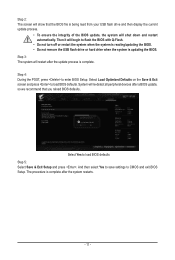
... hard drive when the system is being read from your USB flash drive and then display the current update process. •• To ensure the integrity of the BIOS update, the system will shut down and restart automatically. Step 2: The screen will show that you reload BIOS defaults. Step 4: During the POST, press to load BIOS defaults Step 5: Select Save & Exit Setup and press . Select Yes to enter BIOS Setup...
... hard drive when the system is being read from your USB flash drive and then display the current update process. •• To ensure the integrity of the BIOS update, the system will shut down and restart automatically. Step 2: The screen will show that you reload BIOS defaults. Step 4: During the POST, press to load BIOS defaults Step 5: Select Save & Exit Setup and press . Select Yes to enter BIOS Setup...

Unique Features Introduction
Page 12
... a BIOS switch and a SB switch, reset them to their default settings. (Default setting for 6-8 minutes and the LEDs will stop flashing when the BIOS flashing is complete. • If you choose to update the BIOS manually, first make sure that matches your USB flash drive, and rename it to your motherboard model. 2. Note: The USB flash drive must use FAT32/16/12 file system. 3. default setting for and match the BIOS file in the USB flash drive on the back panel. Connect the power cables to GIGABYTE...
... a BIOS switch and a SB switch, reset them to their default settings. (Default setting for 6-8 minutes and the LEDs will stop flashing when the BIOS flashing is complete. • If you choose to update the BIOS manually, first make sure that matches your USB flash drive, and rename it to your motherboard model. 2. Note: The USB flash drive must use FAT32/16/12 file system. 3. default setting for and match the BIOS file in the USB flash drive on the back panel. Connect the power cables to GIGABYTE...
User Manual
Page 2
Changes to the Quick Installation Guide on your motherboard revision before updating motherboard BIOS, drivers, or when looking for technical information. Check your motherboard looks like this manual may be made by copyright laws and is 1.0. No part of this manual may be reproduced, copied, translated, transmitted, or published in this manual are legally registered to their respective owners. Disclaimer Information in any form...
Changes to the Quick Installation Guide on your motherboard revision before updating motherboard BIOS, drivers, or when looking for technical information. Check your motherboard looks like this manual may be made by copyright laws and is 1.0. No part of this manual may be reproduced, copied, translated, transmitted, or published in this manual are legally registered to their respective owners. Disclaimer Information in any form...
User Manual
Page 3
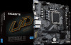
Table of Contents Chapter 1 Product Introduction 4 1-1 Motherboard Layout 4 Chapter 2 Hardware Installation 5 2-1 Installation Precautions 5 2-2 Product Specifications 6 2-3 Installing the CPU and CPU Cooler 9 2-4 Installing the Memory 12 2-5 Installing an Expansion Card 13 2-6 Back Panel Connectors 14 2-7 Internal Connectors 16 Chapter 3 BIOS Setup 26 Chapter 4 Installing the Operating System and Drivers 28 4-1 Operating System Installation 28 4-2 Drivers Installation 29 Chapter 5 Appendix...30 5-1 Configuring a RAID Set 30 Regulatory Notices...31 Contact Us...32 - 3 -
Table of Contents Chapter 1 Product Introduction 4 1-1 Motherboard Layout 4 Chapter 2 Hardware Installation 5 2-1 Installation Precautions 5 2-2 Product Specifications 6 2-3 Installing the CPU and CPU Cooler 9 2-4 Installing the Memory 12 2-5 Installing an Expansion Card 13 2-6 Back Panel Connectors 14 2-7 Internal Connectors 16 Chapter 3 BIOS Setup 26 Chapter 4 Installing the Operating System and Drivers 28 4-1 Operating System Installation 28 4-2 Drivers Installation 29 Chapter 5 Appendix...30 5-1 Configuring a RAID Set 30 Regulatory Notices...31 Contact Us...32 - 3 -
User Manual
Page 5
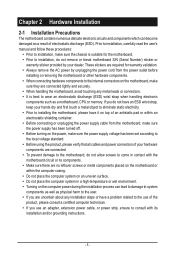
... installing the motherboard, please have a problem related to the use of the product, please consult a certified computer technician. •• If you do not remove or break motherboard S/N (Serial Number) sticker or warranty sticker provided by unplugging the power cord from the motherboard, make sure the power supply has been turned off. •• Before turning on the motherboard, make sure the power supply voltage has been set...
... installing the motherboard, please have a problem related to the use of the product, please consult a certified computer technician. •• If you do not remove or break motherboard S/N (Serial Number) sticker or warranty sticker provided by unplugging the power cord from the motherboard, make sure the power supply has been turned off. •• Before turning on the motherboard, make sure the power supply voltage has been set...
User Manual
Page 6
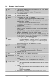
...HDMI 2.0 version and HDCP 2.3. (Graphics specifications may vary depending on CPU support.) Š Realtek® Audio CODEC Š High Definition Audio Š 2/4/5.1/7.1-channel * You can change the functionality of an audio jack using the audio software. To configure 7.1-channel audio, access the audio software for audio settings. Š Support for S/PDIF Out LAN ŠŠ Realtek® GbE LAN chip (1 Gbps/100 Mbps/10 Mbps) Expansion Slots Š Š Storage Interface Š Š Š CPU: - 1 x PCI Express x16 slot, supporting PCIe 4.0 and running at x16 Chipset: - 1 x PCI...
...HDMI 2.0 version and HDCP 2.3. (Graphics specifications may vary depending on CPU support.) Š Realtek® Audio CODEC Š High Definition Audio Š 2/4/5.1/7.1-channel * You can change the functionality of an audio jack using the audio software. To configure 7.1-channel audio, access the audio software for audio settings. Š Support for S/PDIF Out LAN ŠŠ Realtek® GbE LAN chip (1 Gbps/100 Mbps/10 Mbps) Expansion Slots Š Š Storage Interface Š Š Š CPU: - 1 x PCI Express x16 slot, supporting PCIe 4.0 and running at x16 Chipset: - 1 x PCI...
User Manual
Page 7
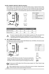
... USB headers) Š 1 x 24-pin ATX main power connector Š 1 x 8-pin ATX 12V power connector Š 1 x CPU fan header Š 2 x system fan headers Š 1 x RGB LED strip header Š 2 x M.2 Socket 3 connectors Š 4 x SATA 6Gb/s connectors Š 1 x front panel header Š 1 x front panel audio header Š 1 x S/PDIF Out header Š 1 x USB 3.2 Gen 1 header Š 2 x USB 2.0/1.1 headers Š 1 x Trusted Platform Module header (For the GC-TPM2.0 SPI/GC-TPM2.0 SPI 2.0 module only) Š 1 x serial port header Š 1 x Clear CMOS jumper Š 2 x USB 2.0/1.1 ports...
... USB headers) Š 1 x 24-pin ATX main power connector Š 1 x 8-pin ATX 12V power connector Š 1 x CPU fan header Š 2 x system fan headers Š 1 x RGB LED strip header Š 2 x M.2 Socket 3 connectors Š 4 x SATA 6Gb/s connectors Š 1 x front panel header Š 1 x front panel audio header Š 1 x S/PDIF Out header Š 1 x USB 3.2 Gen 1 header Š 2 x USB 2.0/1.1 headers Š 1 x Trusted Platform Module header (For the GC-TPM2.0 SPI/GC-TPM2.0 SPI 2.0 module only) Š 1 x serial port header Š 1 x Clear CMOS jumper Š 2 x USB 2.0/1.1 ports...

User Manual
Page 12
... begin to install the memory: •• Make sure that memory of the same capacity, brand, speed, and chips be enabled if only one memory module is installed, the BIOS will double the original memory bandwidth. After the memory is installed. 2. DDR5_A1 DDR5_B1 - 12 - Dual Channel Memory Configuration This motherboard provides two memory sockets and supports Dual Channel Technology. Dual Channel mode cannot be used . (Go to GIGABYTE's website for the latest supported memory speeds and memory modules.) •• Always turn off...
... begin to install the memory: •• Make sure that memory of the same capacity, brand, speed, and chips be enabled if only one memory module is installed, the BIOS will double the original memory bandwidth. After the memory is installed. 2. DDR5_A1 DDR5_B1 - 12 - Dual Channel Memory Configuration This motherboard provides two memory sockets and supports Dual Channel Technology. Dual Channel mode cannot be used . (Go to GIGABYTE's website for the latest supported memory speeds and memory modules.) •• Always turn off...
User Manual
Page 13
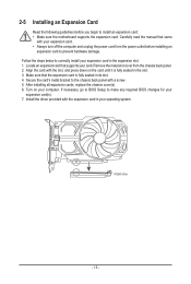
... expansion card in its slot. 4. Make sure that supports your computer. Install the driver provided with your operating system. Follow the steps below to correctly install your expansion card(s). 7. Remove the metal slot cover from the power outlet before you begin to prevent hardware damage. After installing all expansion cards, replace the chassis cover(s). 6. If necessary, go to BIOS Setup to the chassis back panel with the slot, and...
... expansion card in its slot. 4. Make sure that supports your computer. Install the driver provided with your operating system. Follow the steps below to correctly install your expansion card(s). 7. Remove the metal slot cover from the power outlet before you begin to prevent hardware damage. After installing all expansion cards, replace the chassis cover(s). 6. If necessary, go to BIOS Setup to the chassis back panel with the slot, and...

User Manual
Page 14
... used . Do not rock it side to side to a back panel connector, first remove the cable from the connector. 2-6 Back Panel Connectors USB 2.0/1.1 Port The USB port supports the USB 2.0/1.1 specification. Mic In/Center/Subwoofer Speaker Out (Pink) The Mic in jack. •• When removing the cable connected to prevent an electrical short inside the cable connector. - 14 - Connect a monitor that supports D-Sub connection to 192KHz/24bit 7.1-channel LPCM audio output. The maximum supported resolution is compatible to connect your device...
... used . Do not rock it side to side to a back panel connector, first remove the cable from the connector. 2-6 Back Panel Connectors USB 2.0/1.1 Port The USB port supports the USB 2.0/1.1 specification. Mic In/Center/Subwoofer Speaker Out (Pink) The Mic in jack. •• When removing the cable connected to prevent an electrical short inside the cable connector. - 14 - Connect a monitor that supports D-Sub connection to 192KHz/24bit 7.1-channel LPCM audio output. The maximum supported resolution is compatible to connect your device...
User Manual
Page 18
... 4-pin. The speed control function requires the use of a fan with maximum power rating of this motherboard are not configuration jumper blocks. Pin No. Definition 1 12V 2G 1 3R 4B Connect your CPU and system from the power outlet to prevent damage to Pin 1 (12V) of 2A (12V) and maximum length oPfO2RmT . Before installing the devices, be installed inside the chassis. 1 CPU_FAN 1 SYS_FAN1 Pin No. 1 2 3 4 Definition GND Voltage Speed Control Sense PWM Speed Control 1 SYS_FAN2 Connector...
... 4-pin. The speed control function requires the use of a fan with maximum power rating of this motherboard are not configuration jumper blocks. Pin No. Definition 1 12V 2G 1 3R 4B Connect your CPU and system from the power outlet to prevent damage to Pin 1 (12V) of 2A (12V) and maximum length oPfO2RmT . Before installing the devices, be installed inside the chassis. 1 CPU_FAN 1 SYS_FAN1 Pin No. 1 2 3 4 Definition GND Voltage Speed Control Sense PWM Speed Control 1 SYS_FAN2 Connector...

User Manual
Page 19
... Pin No. 1 2 3 4 5 6 7 Definition GND TXP TXN GND RXN RXP GND To enable hot-plugging for the SATA ports, please navigate to the "BIOS Setup" page of GIGABYTE's website and search for "SATA Configuration" for more information. 7) M2A_CPU/M2P_SB (M_3.2 SocUket 3 Connectors) The M.2 connectors on the motherboard support only M.2 PCIe SSDs. 80 M2A_CPU 80 M2P_SB Follow the steps below to the "Configuring a RAID Set" page of GIGABYTE's website for instructions on configuring a RAID...
... Pin No. 1 2 3 4 5 6 7 Definition GND TXP TXN GND RXN RXP GND To enable hot-plugging for the SATA ports, please navigate to the "BIOS Setup" page of GIGABYTE's website and search for "SATA Configuration" for more information. 7) M2A_CPU/M2P_SB (M_3.2 SocUket 3 Connectors) The M.2 connectors on the motherboard support only M.2 PCIe SSDs. 80 M2A_CPU 80 M2P_SB Follow the steps below to the "Configuring a RAID Set" page of GIGABYTE's website for instructions on configuring a RAID...
User Manual
Page 21
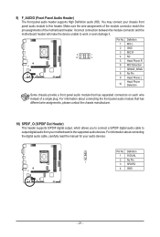
For information about connecting the digital audio cable, carefully read the manual for your audio devices. Incorrect connection between the module connector and the motherboard header will make the device unable to this header. Pin No. You may connect your motherboard to the supported audio devices. For information about connecting the front panel audio module that has different wire assignments, please contact the chassis manufacturer. _ 10) SPDIF_O (S/PDIF Out Header) This header supports S/PDIF digital output, which...
For information about connecting the digital audio cable, carefully read the manual for your audio devices. Incorrect connection between the module connector and the motherboard header will make the device unable to this header. Pin No. You may connect your motherboard to the supported audio devices. For information about connecting the front panel audio module that has different wire assignments, please contact the chassis manufacturer. _ 10) SPDIF_O (S/PDIF Out Header) This header supports S/PDIF digital output, which...
User Manual
Page 24
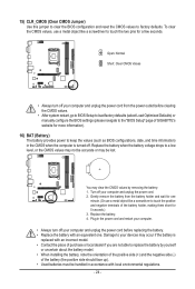
... (Battery) The battery provides power to replace the battery by removing the battery: 1. To clear the CMOS values, use a metal object like a screwdriver to your devices may occur if the battery is turned off. Open: Normal Short: Clear CMOS Values •• Always turn off your computer and unplug the power cord before clearing the CMOS values. •• After system restart, go to BIOS Setup to load factory defaults (select Load Optimized Defaults) or manually configure the BIOS settings...
... (Battery) The battery provides power to replace the battery by removing the battery: 1. To clear the CMOS values, use a metal object like a screwdriver to your devices may occur if the battery is turned off. Open: Normal Short: Clear CMOS Values •• Always turn off your computer and unplug the power cord before clearing the CMOS values. •• After system restart, go to BIOS Setup to load factory defaults (select Load Optimized Defaults) or manually configure the BIOS settings...
User Manual
Page 25
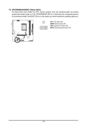
if the BOOT LED is on , that means the corresponding dFe_vUicSeB3 F_ is on , that means you haven't enteB_red the operating system yet. U B_ USB 0_ B CPU DRAM VGA BOOT CPU: CPU status LED DRAM: Memory status LED VGA: Graphics card status LED BOOT: Operating system status LED - 25 - If the CPU/DRAM/VGA LED is not working properly after system power-on. 17) CPU/DRAM/VGA/BOOT (Status LEDs) The status LEDs show whether the CPU, memory, graphics card, and operating system are working normally;
if the BOOT LED is on , that means the corresponding dFe_vUicSeB3 F_ is on , that means you haven't enteB_red the operating system yet. U B_ USB 0_ B CPU DRAM VGA BOOT CPU: CPU status LED DRAM: Memory status LED VGA: Graphics card status LED BOOT: Operating system status LED - 25 - If the CPU/DRAM/VGA LED is not working properly after system power-on. 17) CPU/DRAM/VGA/BOOT (Status LEDs) The status LEDs show whether the CPU, memory, graphics card, and operating system are working normally;
User Manual
Page 26
... system's failure to boot. When the power is turned off, the battery on the motherboard. Q-Flash allows the user to activate certain system features. For instructions on using the Q-Flash utility, please navigate to clear the CMOS values. && Please visit GIGABYTE's website for "BIOS Update Utilities." •• Because BIOS flashing is recommended that allows the user to modify basic system configuration settings or to quickly and easily upgrade or back up BIOS without entering the...
... system's failure to boot. When the power is turned off, the battery on the motherboard. Q-Flash allows the user to activate certain system features. For instructions on using the Q-Flash utility, please navigate to clear the CMOS values. && Please visit GIGABYTE's website for "BIOS Update Utilities." •• Because BIOS flashing is recommended that allows the user to modify basic system configuration settings or to quickly and easily upgrade or back up BIOS without entering the...
User Manual
Page 28
... USB thumb drive. Step 3: Insert the USB thumb drive and then browse to install the operating system. When a screen as shown below : Step 1: Go to GIGABYTE's website, browse to the motherboard model's web page, download the Intel SATA Preinstall driver file on a RAID volume, you to install the Intel® RST VMD Controller driver first during the OS installation process. Step 2: Boot from the Windows setup disc and perform standard OS installation...
... USB thumb drive. Step 3: Insert the USB thumb drive and then browse to install the operating system. When a screen as shown below : Step 1: Go to GIGABYTE's website, browse to the motherboard model's web page, download the Intel SATA Preinstall driver file on a RAID volume, you to install the Intel® RST VMD Controller driver first during the OS installation process. Step 2: Boot from the Windows setup disc and perform standard OS installation...


