Manual
Page 10
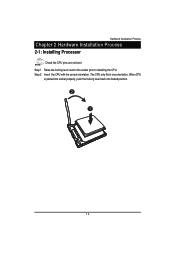
When CPU is placed into socket properly, push the locking lever back into locked position. 2 1 10 Step 1 Raise the locking lever next to the socket prior to installing the CPU. Step 2 Insert the CPU with the correct orientation. Hardware Installation Process Chapter 2 Hardware Installation Process 2-1: Installing Processor Check the CPU pins are not bent. The CPU only fits in one orientation.
When CPU is placed into socket properly, push the locking lever back into locked position. 2 1 10 Step 1 Raise the locking lever next to the socket prior to installing the CPU. Step 2 Insert the CPU with the correct orientation. Hardware Installation Process Chapter 2 Hardware Installation Process 2-1: Installing Processor Check the CPU pins are not bent. The CPU only fits in one orientation.
Manual
Page 24
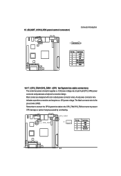
... wires. SYS_FAN1 CPU_FAN1 1 Pin No. 1 2 3 4 Definition GND 12V Sense Control 24 The black connector wire is the ground wire (GND). A red power connector wire indicates a positive connection and requires a +12V power voltage. Remember to connect the CPU/system fan cable to the CPU_FAN/SYS_FAN connector to prevent CPU damage or system...
... wires. SYS_FAN1 CPU_FAN1 1 Pin No. 1 2 3 4 Definition GND 12V Sense Control 24 The black connector wire is the ground wire (GND). A red power connector wire indicates a positive connection and requires a +12V power voltage. Remember to connect the CPU/system fan cable to the CPU_FAN/SYS_FAN connector to prevent CPU damage or system...