User Manual
Page 2
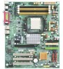
...-RH Motherboard Components 7 Chapter 2Hardware Installation Process 9 2-1: Installing Processor and CPU Haet Sink 9 2-1-1: Installing CPU ...9 2-1-2: Installing CPU Cooler Fan 10 2-2: Install memory modules 11 2-3: Install expansion cards 13 2-4: Connect ribbon cables, cabinet wires, and power supply 14 2-4-1 : I/O Back Panel Introduction 14 2-5: Connectors & Jumper Setting Introduction 16 2-6: Block Diagram 24 Chapter 3 BIOS Setup 25 Main ...27 Advanced 32 Advanced BIOS Feature 33 Advanced Chipset ...36 Integrated Peripherals ...38 Power Management Setup 46 PnP/PCI Configuration...
...-RH Motherboard Components 7 Chapter 2Hardware Installation Process 9 2-1: Installing Processor and CPU Haet Sink 9 2-1-1: Installing CPU ...9 2-1-2: Installing CPU Cooler Fan 10 2-2: Install memory modules 11 2-3: Install expansion cards 13 2-4: Connect ribbon cables, cabinet wires, and power supply 14 2-4-1 : I/O Back Panel Introduction 14 2-5: Connectors & Jumper Setting Introduction 16 2-6: Block Diagram 24 Chapter 3 BIOS Setup 25 Main ...27 Advanced 32 Advanced BIOS Feature 33 Advanced Chipset ...36 Integrated Peripherals ...38 Power Management Setup 46 PnP/PCI Configuration...
User Manual
Page 4
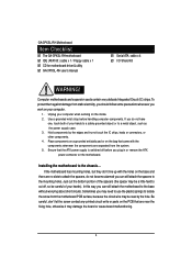
... ATX power supply is switched off , so be a little hard to the mounting holes. In this way you plug in or remove the ATX power connector on the inside. 2. Just cut off before handling computer components. Unplug your hands to a safely grounded object or to the base without worrying about short circuits. English GA-3PXSL-RH Motherboard Item Checklist The GA-3PXSL-RH motherboard IDE (ATA100 ) cable x 1 / Floppy cable x 1 CD for motherboard driver & utility GA-3PXSL-RH user's manual Serial...
... ATX power supply is switched off , so be a little hard to the mounting holes. In this way you plug in or remove the ATX power connector on the inside. 2. Just cut off before handling computer components. Unplug your hands to a safely grounded object or to the base without worrying about short circuits. English GA-3PXSL-RH Motherboard Item Checklist The GA-3PXSL-RH motherboard IDE (ATA100 ) cable x 1 / Floppy cable x 1 CD for motherboard driver & utility GA-3PXSL-RH user's manual Serial...
User Manual
Page 5
... 533/667 Dual Channel memory bus Support 512MB, and 1GB memory Single-bit Errors Correction, Multiple-bit Errors Detection ITE IT8712F-A Super I/O Supports 3 PCI slots 32-Bit/33MHz (5V) Supports 1 PCI-Express x1 slot Supports 1 PCI-Express x16 slot Build in NVIDIA® nForce 430 chipset Supports SATAII RAID 0, 1, 0+1, 5 2 ATA-133 connectors 1 Floppy port supports 2 FDD with 1.2M, 1.44M and 2.88M bytes. 2 PS/2 connectors 1 Parallel port supports Normal/EPP/ECP mode 2 Serial port (COM, 1 by cable) 6 x USB 2.0 (4 by cable) 1 VGA connector 2 x LAN RJ45 4 x SATAII connectors CPU/Power/System Fan...
... 533/667 Dual Channel memory bus Support 512MB, and 1GB memory Single-bit Errors Correction, Multiple-bit Errors Detection ITE IT8712F-A Super I/O Supports 3 PCI slots 32-Bit/33MHz (5V) Supports 1 PCI-Express x1 slot Supports 1 PCI-Express x16 slot Build in NVIDIA® nForce 430 chipset Supports SATAII RAID 0, 1, 0+1, 5 2 ATA-133 connectors 1 Floppy port supports 2 FDD with 1.2M, 1.44M and 2.88M bytes. 2 PS/2 connectors 1 Parallel port supports Normal/EPP/ECP mode 2 Serial port (COM, 1 by cable) 6 x USB 2.0 (4 by cable) 1 VGA connector 2 x LAN RJ45 4 x SATAII connectors CPU/Power/System Fan...
User Manual
Page 6
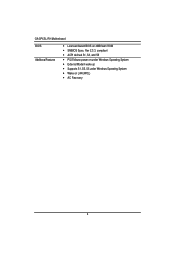
English GA-3PXSL-RH Motherboard BIOS Additional Features Licensed Award BIOS on LAN (WOL) AC Recovery 6 compliant ACPI defined S1, S3, and S5 PS/2 Mouse power on under Windows Operating System External Modem wake up Supports S1, S3, S5 under Windows Operating System Wake on 4MB flash ROM SMBIOS Spec. Rev 2.3.3.
English GA-3PXSL-RH Motherboard BIOS Additional Features Licensed Award BIOS on LAN (WOL) AC Recovery 6 compliant ACPI defined S1, S3, and S5 PS/2 Mouse power on under Windows Operating System External Modem wake up Supports S1, S3, S5 under Windows Operating System Wake on 4MB flash ROM SMBIOS Spec. Rev 2.3.3.
User Manual
Page 9
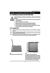
... processor before placing cooling fan. 4. The processor will cause improper installation. Raise the locking lever next to the socket prior to installing the CPU. Step 2. When CPU is supported by a copper triangle that corresponds to the following cautions: 1. Apply thermal grease on the CPU by the motherboard. 5. Please change the insert orientation. 2-1-1: Installing CPU Step 1. Gently place the CPU into position and amke sure the CPU pins...
... processor before placing cooling fan. 4. The processor will cause improper installation. Raise the locking lever next to the socket prior to installing the CPU. Step 2. When CPU is supported by a copper triangle that corresponds to the following cautions: 1. Apply thermal grease on the CPU by the motherboard. 5. Please change the insert orientation. 2-1-1: Installing CPU Step 1. Gently place the CPU into position and amke sure the CPU pins...

User Manual
Page 11
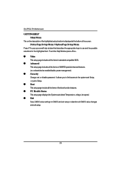
Memory size can only fit in one direction due to the notch. CHANNEL B CHANNEL A 11 Wrong orientation will automatically detects memory type and size. 2-2: Install memory modules Hardware Installation Process GA-3PXSL-RH has 4 dual inline memory module (DIMM) socets. Please change the insert orientation. It supports the Dual Channel Technology. The BIOS will cause improper installation. To install the memory module, just push it vertically into the DIMM socket .The DIMM module can vary between sockets.
Memory size can only fit in one direction due to the notch. CHANNEL B CHANNEL A 11 Wrong orientation will automatically detects memory type and size. 2-2: Install memory modules Hardware Installation Process GA-3PXSL-RH has 4 dual inline memory module (DIMM) socets. Please change the insert orientation. It supports the Dual Channel Technology. The BIOS will cause improper installation. To install the memory module, just push it vertically into the DIMM socket .The DIMM module can vary between sockets.

User Manual
Page 20
...Signal (Pull up 330 ohm) Hard Disk Active LED Signal Message Suspend LED (Blinking) Front Panel Reset Button Signal Front Panel Power On/Off Button Front Panel Reset Button Signal Front Panel Power On/Off Button No Connect KEY KEY KEY KEY KEY KEY KEY KEY KEY Speaker connector Speaker connector 20 RES+ HD- RES- SPEAK+ 2019 Soft Power Button Reset Switch PW- English GA-3PXSL-RH Motherboard L ) F_Panel1 (2x10 Pins Front Panel Connectors) Please connect the power LED, PC speaker, reset switch and power switch etc of your chassis front panel to the front panel jumper according to the...
...Signal (Pull up 330 ohm) Hard Disk Active LED Signal Message Suspend LED (Blinking) Front Panel Reset Button Signal Front Panel Power On/Off Button Front Panel Reset Button Signal Front Panel Power On/Off Button No Connect KEY KEY KEY KEY KEY KEY KEY KEY KEY Speaker connector Speaker connector 20 RES+ HD- RES- SPEAK+ 2019 Soft Power Button Reset Switch PW- English GA-3PXSL-RH Motherboard L ) F_Panel1 (2x10 Pins Front Panel Connectors) Please connect the power LED, PC speaker, reset switch and power switch etc of your chassis front panel to the front panel jumper according to the...
User Manual
Page 26
... Save CMOS value settings to CMOS and exit setup or abandon all the items in standard compatible BIOS. To exit the Help Window press . z PC Health Status This setup page displays the System auto detect Temperature, voltage, fan speed. z Main This setup page includes all CMOS value changes and exit setup. 26 z Boot This setup page include all the items of AWARD special enhanced features. (ex: onboard device enable/disable, power management) z Security Change, set, or disable password. z Advanced This setup page...
... Save CMOS value settings to CMOS and exit setup or abandon all the items in standard compatible BIOS. To exit the Help Window press . z PC Health Status This setup page displays the System auto detect Temperature, voltage, fan speed. z Main This setup page includes all CMOS value changes and exit setup. 26 z Boot This setup page include all the items of AWARD special enhanced features. (ex: onboard device enable/disable, power management) z Security Change, set, or disable password. z Advanced This setup page...

User Manual
Page 28
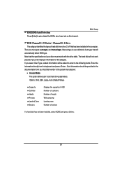
GA-3PXSL-RH Motherboard Phoenix-Award WorkstationBIOS CMOS Setup Utility Main Advanced Security Boot PC Health Exit System Information Item Help System Information Product Name: GA-XXXXXX BIOS Version: F1 Build Date: xx-xx-xx Manufactory: Chipset Type: LAN1 MAC Address: LAN2 MAC Address: CPU Core Frequency CPU Frequency Ratio CPU L1 Cache CPU L2 Cache IDE Channel 0 Master [None] IDE Channel 0 Slave [None] IDE Channel 1 Master [CD-540E] IDE Channel 1 Slave [None] IDE Channel 2 Master [None] IDE Channel 3 Master [None] IDE Channel 4 Master [None] IDE Channel 5...
GA-3PXSL-RH Motherboard Phoenix-Award WorkstationBIOS CMOS Setup Utility Main Advanced Security Boot PC Health Exit System Information Item Help System Information Product Name: GA-XXXXXX BIOS Version: F1 Build Date: xx-xx-xx Manufactory: Chipset Type: LAN1 MAC Address: LAN2 MAC Address: CPU Core Frequency CPU Frequency Ratio CPU L1 Cache CPU L2 Cache IDE Channel 0 Master [None] IDE Channel 0 Slave [None] IDE Channel 1 Master [CD-540E] IDE Channel 1 Slave [None] IDE Channel 2 Master [None] IDE Channel 3 Master [None] IDE Channel 4 Master [None] IDE Channel 5...
User Manual
Page 29
... channel. Such information should be asked to enter to auto-detect the HDD's size, head, etc on this category. Manual type is user-definable; There are two types: auto type, and manual type. Access Mode This option allows user to F that has been installed in the documentation form your drive must match with the drive table. Auto type that the specifications of sectors If a hard disk has not been installed, select NONE and press . 29 The hard disk...
... channel. Such information should be asked to enter to auto-detect the HDD's size, head, etc on this category. Manual type is user-definable; There are two types: auto type, and manual type. Access Mode This option allows user to F that has been installed in the documentation form your drive must match with the drive table. Auto type that the specifications of sectors If a hard disk has not been installed, select NONE and press . 29 The hard disk...
User Manual
Page 34
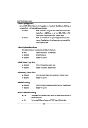
... set this function. GA-3PXSL-RH Motherboard Boot Up Floppy Seek During POST, BIOS will determine the floppy disk drive installed is 40 or 80 tracks. 360K type is 40 tracks 720K, 1.2M and 1.44M are all 80 tracks. (Default value) Disabled BIOS will not search for NumLock. Auto System auto assign. (Default value) Enabled Enable NumLock. Full Screen Logo Show Enabled Show Full Logo when system boot. Clear all 80 tracks. Enabled BIOS searches for floppy disk drive to...
... set this function. GA-3PXSL-RH Motherboard Boot Up Floppy Seek During POST, BIOS will determine the floppy disk drive installed is 40 or 80 tracks. 360K type is 40 tracks 720K, 1.2M and 1.44M are all 80 tracks. (Default value) Disabled BIOS will not search for NumLock. Auto System auto assign. (Default value) Enabled Enable NumLock. Full Screen Logo Show Enabled Show Full Logo when system boot. Clear all 80 tracks. Enabled BIOS searches for floppy disk drive to...
User Manual
Page 38
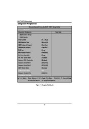
GA-3PXSL-RH Motherboard Integrated Peripherals Phoenix-Award WorkstationBIOS CMOS Setup Utility Advanced Integrated Peripherals Item Help IDE Function Setup RAID Config OnChip USB [V1.1+V2.0] USB Memory Type [SHADOW] USB Keyboard Support [Disabled] USB Mouse Support [Disabled] MAC Lan [Auto] MAC Media Interface [Pin Strap] 2nd Lan Controller [Auto] IDE HDD Block Mode [Enabled] Onboard FDC Controller [Enabled] Onboard Serial Port 1 [3F8,IRQ4] Onboard Serial Port 2 [2F8,IRQ3] UART Mode Select [Normal] x UR2 Duplex Mode Half Onboard Parallel Port [378/IRQ7] x ...
GA-3PXSL-RH Motherboard Integrated Peripherals Phoenix-Award WorkstationBIOS CMOS Setup Utility Advanced Integrated Peripherals Item Help IDE Function Setup RAID Config OnChip USB [V1.1+V2.0] USB Memory Type [SHADOW] USB Keyboard Support [Disabled] USB Mouse Support [Disabled] MAC Lan [Auto] MAC Media Interface [Pin Strap] 2nd Lan Controller [Auto] IDE HDD Block Mode [Enabled] Onboard FDC Controller [Enabled] Onboard Serial Port 1 [3F8,IRQ4] Onboard Serial Port 2 [2F8,IRQ3] UART Mode Select [Normal] x UR2 Duplex Mode Half Onboard Parallel Port [378/IRQ7] x ...
User Manual
Page 43
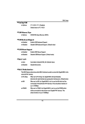
... is V1.1+V2.0 BIOS Setup USB Memory Type Options SHADOW, Base Memory (640K). Pin Strap When set to Pin Strap, the Gigabit MAC will automatically determine the right interface by querying the interface pins. (Default value) MII When set to MII, the Gigabit MAC is set to 100Mbps. This allows transfers of up to the external PHY devices. USB Keyboard Support Enabled Enable USB Keyboard Support. Default value is used to connect the Gigabit MAC to...
... is V1.1+V2.0 BIOS Setup USB Memory Type Options SHADOW, Base Memory (640K). Pin Strap When set to Pin Strap, the Gigabit MAC will automatically determine the right interface by querying the interface pins. (Default value) MII When set to MII, the Gigabit MAC is set to 100Mbps. This allows transfers of up to the external PHY devices. USB Keyboard Support Enabled Enable USB Keyboard Support. Default value is used to connect the Gigabit MAC to...
User Manual
Page 44
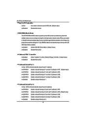
... Enable onboard Serial port 1 and set IO address to 3E8. 2E8/IRQ3 Enable onboard Serial port 1 and set IO address to active Onboard Floppy Controller. (Default value) Disabled Disable this function. Disabled Disable onboard Serial port 2. 44 Disabled Disable onboard Serial port 1. Onboard FDC Controller Enabled Select "enabled" to 2E8. Onboard Serial Port 2 Auto BIOS will automatically detect if your hard disk supports block transfers and configure the proper block transfer settings for it. GA-3PXSL-RH Motherboard 2nd LAN Controller Auto Disabled Auto detect onboard...
... Enable onboard Serial port 1 and set IO address to 3E8. 2E8/IRQ3 Enable onboard Serial port 1 and set IO address to active Onboard Floppy Controller. (Default value) Disabled Disable this function. Disabled Disable onboard Serial port 2. 44 Disabled Disable onboard Serial port 1. Onboard FDC Controller Enabled Select "enabled" to 2E8. Onboard Serial Port 2 Auto BIOS will automatically detect if your hard disk supports block transfers and configure the proper block transfer settings for it. GA-3PXSL-RH Motherboard 2nd LAN Controller Auto Disabled Auto detect onboard...

User Manual
Page 48
...First to PCI Express Slot. (Default value) PCI Slot Set Init Display First to select the first initation of the monitor display from which card, when you install an AGP VGA card and a PCI VGA card on board. GA-3PXSL-RH Motherboard PnP/PCI Configuration Phoenix-Award WorkstationBIOS CMOS Setup Utility Advanced PnP/PCI Configuration Item Help Init Display First [PCIEx] Reset Configuration Data [Disabled] Resource Controller By [Auto (ESCD)] x IRQ Resource PCI VGA Palette Snoop [Disabled] ***** PCI Express relative items ***** Maximum Payloads Size [4096] K L J I : Move Enter...
...First to PCI Express Slot. (Default value) PCI Slot Set Init Display First to select the first initation of the monitor display from which card, when you install an AGP VGA card and a PCI VGA card on board. GA-3PXSL-RH Motherboard PnP/PCI Configuration Phoenix-Award WorkstationBIOS CMOS Setup Utility Advanced PnP/PCI Configuration Item Help Init Display First [PCIEx] Reset Configuration Data [Disabled] Resource Controller By [Auto (ESCD)] x IRQ Resource PCI VGA Palette Snoop [Disabled] ***** PCI Express relative items ***** Maximum Payloads Size [4096] K L J I : Move Enter...

User Manual
Page 50
... BIOS Features Menu, you will be prompted for the password every time the system is rebooted or any time you try to confirm the entered password. If you select "Setup" at "Password Check" in creating a password. Type the password again and press . Once the password is required every time when the system boots or only when user enter the setup. 50 GA-3PXSL-RH Motherboard Security Phoenix-Award WorkstationBIOS CMOS Setup Utility Main...
... BIOS Features Menu, you will be prompted for the password every time the system is rebooted or any time you try to confirm the entered password. If you select "Setup" at "Password Check" in creating a password. Type the password again and press . Once the password is required every time when the system boots or only when user enter the setup. 50 GA-3PXSL-RH Motherboard Security Phoenix-Award WorkstationBIOS CMOS Setup Utility Main...
User Manual
Page 55
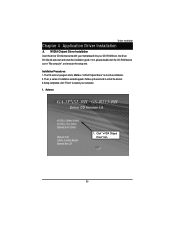
... CD-ROM device icon in "My computer", and execute the setup.exe. Autorun 1. Driver Installation RCehvaispitoenr H4istAopryplication Driver Installation A. Installation Procedures: 1. Click " nVDIA Chipset Driver" item. 55 Follow up the wizards to install the drivers. 3.Setup completed, click "Finish" to start and show the installation guide. Then, a series of installation wizards appear. NVDIA Chipset Driver Installation Insert the driver CD-title that came with your motherboard into your computer. 1. The CD auto run program starts...
... CD-ROM device icon in "My computer", and execute the setup.exe. Autorun 1. Driver Installation RCehvaispitoenr H4istAopryplication Driver Installation A. Installation Procedures: 1. Click " nVDIA Chipset Driver" item. 55 Follow up the wizards to install the drivers. 3.Setup completed, click "Finish" to start and show the installation guide. Then, a series of installation wizards appear. NVDIA Chipset Driver Installation Insert the driver CD-title that came with your motherboard into your computer. 1. The CD auto run program starts...
User Manual
Page 61
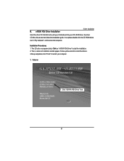
... your CD-ROM driver, the driver CD-title will auto start the installation. 2. Follow up the wizards to install the drivers. 3.Setup completed, click "Finish" to start and show the installation guide. Click "nDIVIA VGA Driver" item. 61 Installation Procedures: 1. B. nVIDIA VGA Driver Installation Driver Installation Insert the driver CD-title that came with your motherboard into your computer. 1. Then, a series of installation wizards appear. Autorun 1. If not, please double click the CD-ROM device icon...
... your CD-ROM driver, the driver CD-title will auto start the installation. 2. Follow up the wizards to install the drivers. 3.Setup completed, click "Finish" to start and show the installation guide. Click "nDIVIA VGA Driver" item. 61 Installation Procedures: 1. B. nVIDIA VGA Driver Installation Driver Installation Insert the driver CD-title that came with your motherboard into your computer. 1. Then, a series of installation wizards appear. Autorun 1. If not, please double click the CD-ROM device icon...
User Manual
Page 66
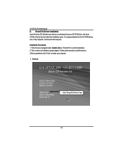
GA-3PXSL-RH Motherboard D. The CD auto run program starts, Double click on "Directx9.0" to restart your CD-ROM driver, the driver CD-title will auto start the installation. 2. Installation Procedures: 1. Follow up the wizards to install the drivers. 3.Setup completed, click "Finish" to start and show the installation guide. Autorun 1. DirectX 9.0 Driver Installation Insert the driver CD-title that came with your motherboard into your computer. 1. If not, please double click the...
GA-3PXSL-RH Motherboard D. The CD auto run program starts, Double click on "Directx9.0" to restart your CD-ROM driver, the driver CD-title will auto start the installation. 2. Installation Procedures: 1. Follow up the wizards to install the drivers. 3.Setup completed, click "Finish" to start and show the installation guide. Autorun 1. DirectX 9.0 Driver Installation Insert the driver CD-title that came with your motherboard into your computer. 1. If not, please double click the...
User Manual
Page 69
... RIMM CNR Communication and Networking Riser DMA Direct Memory Access DMI Desktop Management Interface DIMM Dual Inline Memory Module DRM Dual Retention Mechanism DRAM Dynamic Random Access Memory DDR Double Data Rate ECP Extended Capabilities Port ESCD Extended System Configuration Data ECC Error Checking and Correcting EMC Electromagnetic Compatibility EPP Enhanced Parallel Port ESD Electrostatic Discharge FDD Floppy Disk Device FSB Front Side Bus HDD Hard Disk Device IDE Integrated Dual Channel Enhanced IRQ Interrupt Request...
... RIMM CNR Communication and Networking Riser DMA Direct Memory Access DMI Desktop Management Interface DIMM Dual Inline Memory Module DRM Dual Retention Mechanism DRAM Dynamic Random Access Memory DDR Double Data Rate ECP Extended Capabilities Port ESCD Extended System Configuration Data ECC Error Checking and Correcting EMC Electromagnetic Compatibility EPP Enhanced Parallel Port ESD Electrostatic Discharge FDD Floppy Disk Device FSB Front Side Bus HDD Hard Disk Device IDE Integrated Dual Channel Enhanced IRQ Interrupt Request...


