

User Manual
Page 6
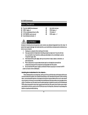
... Features 9 GA-7A8DR-H Motherboard Layout 11 Chapter 2 Hardware Installation Process 13 Step 1: Installing Processor and CPU Cooling Fan 14 Step1-1: Installing CPU 14 Step1-2: Installing Cooling Fan 16 Step 2: Install memory modules 18 Step 3: Install expansion cards 22 Step 4: Connect ribbon cables, cabinet wires, and power supply 23 Step4-1:I/O Back Panel Introduction 23 Step4-2: Connectors Introduction 26 Step4-3: Jumper Setting Introduction 37 Chapter 3 BIOS Setup 41 Main ...43 Advanced 47 Chipset Configuration ...50 Keyboard Configuration 53 I/O Device Configuration 54 PCI...
... Features 9 GA-7A8DR-H Motherboard Layout 11 Chapter 2 Hardware Installation Process 13 Step 1: Installing Processor and CPU Cooling Fan 14 Step1-1: Installing CPU 14 Step1-2: Installing Cooling Fan 16 Step 2: Install memory modules 18 Step 3: Install expansion cards 22 Step 4: Connect ribbon cables, cabinet wires, and power supply 23 Step4-1:I/O Back Panel Introduction 23 Step4-2: Connectors Introduction 26 Step4-3: Jumper Setting Introduction 37 Chapter 3 BIOS Setup 41 Main ...43 Advanced 47 Chipset Configuration ...50 Keyboard Configuration 53 I/O Device Configuration 54 PCI...
User Manual
Page 8
... attach the spacers to a metal object, such as the power supply case. 3. The GA-7A8DRH motherboard ; CD for motherboard driver & utility ; GA-7A8DRH user's manual ; Quick Reference Guide x 1 ; Use a grounded wrist strap before you do not become alarmed you can still attach the motherboard to the base without worrying about short circuits. If you plug in or remove the ATX power connector on the bag that are separated from the system. 5. If...
... attach the spacers to a metal object, such as the power supply case. 3. The GA-7A8DRH motherboard ; CD for motherboard driver & utility ; GA-7A8DRH user's manual ; Quick Reference Guide x 1 ; Use a grounded wrist strap before you do not become alarmed you can still attach the motherboard to the base without worrying about short circuits. If you plug in or remove the ATX power connector on the bag that are separated from the system. 5. If...
User Manual
Page 9
....9cm ATX size form factor, 6 layers PCB. AMD-8131 North Bridge HyperTransport PCI-X chipset provides two independent, high-performance PCI-X bus bridges, interated with 360K, 720K,1.2M, 1.44M and 2.88M bytes. 1 Parallel port supports Normal/EPP/ECP mode 1 Serial ports (COMA) 1 VGA connector 2 USB ports (USB1.1) to be continued...... 9 GA-7A8DRH Motherboard Support Dual Opteron processors (Sledge Hammer) The HyperTransport link of the AMD Opteron processor is capable of Features Form Factor Motherboard CPU Chipset Memory I /O Hub replaces the traditional...
....9cm ATX size form factor, 6 layers PCB. AMD-8131 North Bridge HyperTransport PCI-X chipset provides two independent, high-performance PCI-X bus bridges, interated with 360K, 720K,1.2M, 1.44M and 2.88M bytes. 1 Parallel port supports Normal/EPP/ECP mode 1 Serial ports (COMA) 1 VGA connector 2 USB ports (USB1.1) to be continued...... 9 GA-7A8DRH Motherboard Support Dual Opteron processors (Sledge Hammer) The HyperTransport link of the AMD Opteron processor is capable of Features Form Factor Motherboard CPU Chipset Memory I /O Hub replaces the traditional...
User Manual
Page 10
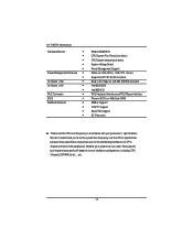
... will depend on 4Mb flash RAM SMBus Support IOAPIC Support Serial IRQ Support AC Recovery 0 Please set the system bus frequency over the CPU's specification because these specific bus frequencies are not the standard specifications for CPU, chipset and most of the peripherals. GA-7A8DRH Motherboard Hardware Monitor Power Managerment Features On-Board VGA On-Board LAN PS/2 Connector BIOS Additional Features Winbond W83791D CPU/System Fan Revolution detect CPU/System temperature detect System Voltage Detect Power Management Support Wake-on-LAN (WOL), USB, PCI, mouse Supports ACPI S1/S4/S5...
... will depend on 4Mb flash RAM SMBus Support IOAPIC Support Serial IRQ Support AC Recovery 0 Please set the system bus frequency over the CPU's specification because these specific bus frequencies are not the standard specifications for CPU, chipset and most of the peripherals. GA-7A8DRH Motherboard Hardware Monitor Power Managerment Features On-Board VGA On-Board LAN PS/2 Connector BIOS Additional Features Winbond W83791D CPU/System Fan Revolution detect CPU/System temperature detect System Voltage Detect Power Management Support Wake-on-LAN (WOL), USB, PCI, mouse Supports ACPI S1/S4/S5...
User Manual
Page 12
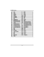
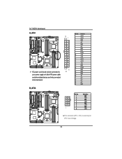
Intel 82541GI G. PWR_FAN2 (Power Fan) J. CPU_FAN2 (CPU Fan) M. IDE2 U. FDD1 Z. ATX2 (SSI power connector) II. CPU1 DIMM 0~3 LL. PCI_6 NN. Front Panel S. KB_MS (Keyboard/Mouse) HH. PCI-X_4 PP. PCI-X_3 QQ PCI-X_2 RR. ATI_Rage XL 12 Intel 845GM F. EM638325TS-6 I. USB1 (Front USB) T. COMB AA. USB3 GG. GA-7A8DRH Motherboard A. CPU1 B. CPU2 C. AMD8131 D. AMD8111 E. BIOS H. PWR_FAN1 (Power Fan) K. ITE8712 L. CPU_FAN1 (CPU Fan) N. SYS_FAN2 (System Fan) O. SYS_FAN1 (System Fan) P. WOL Q. WOM R. IDE1 V. GSMI (IPMI...
Intel 82541GI G. PWR_FAN2 (Power Fan) J. CPU_FAN2 (CPU Fan) M. IDE2 U. FDD1 Z. ATX2 (SSI power connector) II. CPU1 DIMM 0~3 LL. PCI_6 NN. Front Panel S. KB_MS (Keyboard/Mouse) HH. PCI-X_4 PP. PCI-X_3 QQ PCI-X_2 RR. ATI_Rage XL 12 Intel 845GM F. EM638325TS-6 I. USB1 (Front USB) T. COMB AA. USB3 GG. GA-7A8DRH Motherboard A. CPU1 B. CPU2 C. AMD8131 D. AMD8111 E. BIOS H. PWR_FAN1 (Power Fan) K. ITE8712 L. CPU_FAN1 (CPU Fan) N. SYS_FAN2 (System Fan) O. SYS_FAN1 (System Fan) P. WOL Q. WOM R. IDE1 V. GSMI (IPMI...

User Manual
Page 13
Install supporting software tools Step 3 Step 2 Step 5 Step 4 㕡 㕢 㕡 㕧㕠 㕷 㖉 㕷 㖉 ...13684; 㕱㕵 㕱㕶 Step 4 Step 1 13 Step 2 Connect ribbon cables, cabinet wires, and power supply Step 5- Install memory modules Step 3- Setup BIOS software Step 6- Install expansion cards Step 4- Install the Central Processing Unit (CPU) Step 2- Hardware Installation Process Chapter 2 Hardware Installation Process To set up your computer, you must complete the following steps: Step 1-
Install supporting software tools Step 3 Step 2 Step 5 Step 4 㕡 㕢 㕡 㕧㕠 㕷 㖉 㕷 㖉 ...13684; 㕱㕵 㕱㕶 Step 4 Step 1 13 Step 2 Connect ribbon cables, cabinet wires, and power supply Step 5- Install memory modules Step 3- Setup BIOS software Step 6- Install expansion cards Step 4- Install the Central Processing Unit (CPU) Step 2- Hardware Installation Process Chapter 2 Hardware Installation Process To set up your computer, you must complete the following steps: Step 1-
User Manual
Page 14
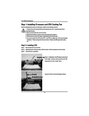
... not match the CPU socket Pin 1 and CPU cut edge well, it will overheat without the heatsink and/or fan, resulting in permanent irreparable damage. 2. Aligning the pins of tight , and then continue pull the rod to the 90-degree directly. Actuation Lever 14 Please use AMD approved cooling fan. GA-7A8DRH Motherboard Step 1: Installing Processor and CPU Cooling Fan Before installing the processor and cooling fan, adhere to the...
... not match the CPU socket Pin 1 and CPU cut edge well, it will overheat without the heatsink and/or fan, resulting in permanent irreparable damage. 2. Aligning the pins of tight , and then continue pull the rod to the 90-degree directly. Actuation Lever 14 Please use AMD approved cooling fan. GA-7A8DRH Motherboard Step 1: Installing Processor and CPU Cooling Fan Before installing the processor and cooling fan, adhere to the...
User Manual
Page 18
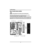
... 18 GA-7A8DRH Motherboard Step 2: Install memory modules Before installing the processor and heatsink, adhere to the following warning: Please note that the DIMM module can only fit in one direction due to the one direction due to the notch. Please change the insert orientation. Memory size can only fit in one notches. Wrong orientation will automatically detects memory type and size. To install the memory...
... 18 GA-7A8DRH Motherboard Step 2: Install memory modules Before installing the processor and heatsink, adhere to the following warning: Please note that the DIMM module can only fit in one direction due to the one direction due to the notch. Please change the insert orientation. Memory size can only fit in one notches. Wrong orientation will automatically detects memory type and size. To install the memory...
User Manual
Page 28
...Definition 1 GND 2 +12v 3 GND 4 +12V 5 GND 6 +12V 7 GND 1 8 +12V ¾This connector (ATX +12V) is used only for CPU Core Voltage. 28 㕶 㕡㕣 㕵 GA-7A8DRH Motherboard A ) ATX1 㕡 㕢 㕷 㖉 㕷 㖉 㕡㕤 㕡㕠 㕥...; 㕱㕵 㕱㕶 㕦 ¾ AC power cord should only be connected to your power supply unit after ATX power cable and other related devices are firmly connected to the mainboard. 12 24 B ) ATX2 PIN No. 1 2 3 4 5 6 7 8 9 10...
...Definition 1 GND 2 +12v 3 GND 4 +12V 5 GND 6 +12V 7 GND 1 8 +12V ¾This connector (ATX +12V) is used only for CPU Core Voltage. 28 㕶 㕡㕣 㕵 GA-7A8DRH Motherboard A ) ATX1 㕡 㕢 㕷 㖉 㕷 㖉 㕡㕤 㕡㕠 㕥...; 㕱㕵 㕱㕶 㕦 ¾ AC power cord should only be connected to your power supply unit after ATX power cable and other related devices are firmly connected to the mainboard. 12 24 B ) ATX2 PIN No. 1 2 3 4 5 6 7 8 9 10...

User Manual
Page 42
.... GA-7A8DRH Motherboard GETTINGHELP Main Menu The on-line description of the highlighted setup function is displayed at the bottom of AMI special enhanced features. (ex: Auto detect fan and temperature status, automatically configure hard disk parameters.) z Security Change, set, or disable password. z Boot This setup page include all the items of the screen. z Main This setup page includes all the items in standard compatible BIOS. To exit the Help Window press . Status Page Setup Menu / Option Page Setup Menu...
.... GA-7A8DRH Motherboard GETTINGHELP Main Menu The on-line description of the highlighted setup function is displayed at the bottom of AMI special enhanced features. (ex: Auto detect fan and temperature status, automatically configure hard disk parameters.) z Security Change, set, or disable password. z Boot This setup page include all the items of the screen. z Main This setup page includes all the items in standard compatible BIOS. To exit the Help Window press . Status Page Setup Menu / Option Page Setup Menu...
User Manual
Page 44
... the specifications of your hard disk vendor or the system manufacturer. ATAPI Removable: Removable disk drive is user-definable; Users: Set parameters by User. GA-7A8DRH Motherboard Legacy Diskette A This category identifies the type of floppy disk drive A that has been installed in the documentation form your drive must match with the drive table. Such information should be asked to enter to the following items. Enter the information directly from drive C to set all HDD parameters automatically. Auto: Set...
... the specifications of your hard disk vendor or the system manufacturer. ATAPI Removable: Removable disk drive is user-definable; Users: Set parameters by User. GA-7A8DRH Motherboard Legacy Diskette A This category identifies the type of floppy disk drive A that has been installed in the documentation form your drive must match with the drive table. Such information should be asked to enter to the following items. Enter the information directly from drive C to set all HDD parameters automatically. Auto: Set...
User Manual
Page 47
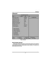
... Setup Utility Main Advanced Security Boot Exit Boot Summary Screen [Disabled] Onboard USB controller [Enabled] 4GB Memory Hole Adjust [Auto] 4GB Memory Hole Size [64MB] Multiprocessor Specification [1.4] MP Table uses PCI entries [Yes] After Power Failure [Power On] CLK Spread spectrum [Diabled] BIOS Setup Item Specific Help Chipset Configuration Keyboard Configuration I/O Device Configuration PCI Configuration Hardware Monitor Console Redirection F1: Help Esc: Exit KL: Select Item IJ: Select Menu + -: Change Values F5: Setup Defaults Enter: Select Sub-Menu...
... Setup Utility Main Advanced Security Boot Exit Boot Summary Screen [Disabled] Onboard USB controller [Enabled] 4GB Memory Hole Adjust [Auto] 4GB Memory Hole Size [64MB] Multiprocessor Specification [1.4] MP Table uses PCI entries [Yes] After Power Failure [Power On] CLK Spread spectrum [Diabled] BIOS Setup Item Specific Help Chipset Configuration Keyboard Configuration I/O Device Configuration PCI Configuration Hardware Monitor Console Redirection F1: Help Esc: Exit KL: Select Item IJ: Select Menu + -: Change Values F5: Setup Defaults Enter: Select Sub-Menu...
User Manual
Page 48
...(MP) specification revision level. Enabled Set this item to enabled to 'Manual', user can select the memory hole size in this function. Enabled Enable onboard USB controller. (Default) Disabled Disable this function. 4GB Memory Hole Adjust Auto Set this item to 'Auto' to adjust the memory hole size automatically according to the memory space used by PCI devices. (Default) Manual Memory hole sizeis determined manually. 4GB Memory Hole Size When 4GB Memory Hole Adjust option is set to displays the system configuration on boot. GA-7A8DRH Motherboard Boot Summary Screen This item...
...(MP) specification revision level. Enabled Set this item to enabled to 'Manual', user can select the memory hole size in this function. Enabled Enable onboard USB controller. (Default) Disabled Disable this function. 4GB Memory Hole Adjust Auto Set this item to 'Auto' to adjust the memory hole size automatically according to the memory space used by PCI devices. (Default) Manual Memory hole sizeis determined manually. 4GB Memory Hole Size When 4GB Memory Hole Adjust option is set to displays the system configuration on boot. GA-7A8DRH Motherboard Boot Summary Screen This item...
User Manual
Page 49
After Power Failure This option provides user to the last sate when AC power is removed. Power On System power state when AC cord is re-plugged. (Default) Off State Do not power on system when AC power is back. Last State Set system to set the mode of operation if an AC / power loss occurs. Yes MP Table uses with PCI interrupt entries. Do not power on system when AC power is back. 49 Connector and Jumper Setting Introduction MP Table uses PCI entries This option allows user to configure the MP Table with PCI interrupt entries. (Default) No Disable this function.
After Power Failure This option provides user to the last sate when AC power is removed. Power On System power state when AC cord is re-plugged. (Default) Off State Do not power on system when AC power is back. Last State Set system to set the mode of operation if an AC / power loss occurs. Yes MP Table uses with PCI interrupt entries. Do not power on system when AC power is back. 49 Connector and Jumper Setting Introduction MP Table uses PCI entries This option allows user to configure the MP Table with PCI interrupt entries. (Default) No Disable this function.
User Manual
Page 56
.../ D800-DBFF/ DC00-DFFF 56 GA-7A8DRH Motherboard Enable Master Enable selected device as a PCI bus mater. (Default) Disabled Disable this function. Disabled Disable this function.(Default) 82545 PXE Function This option allows user to set the onboard LAN 82541GI PXE function. Enabled Enable onboard LAN 82541GI PXE function. (Default) Disabled Disable this SCSI Option ROM funtion first. IRQ3/ IRQ4/ IRQ5/ IRQ7/ IRQ10/ IRQ11 PCI / PNP UMB Exclusion Reserve specific upper memory blocks for use by legacy ISA devices. Latency Timer Minimum guranteed time...
.../ D800-DBFF/ DC00-DFFF 56 GA-7A8DRH Motherboard Enable Master Enable selected device as a PCI bus mater. (Default) Disabled Disable this function. Disabled Disable this function.(Default) 82545 PXE Function This option allows user to set the onboard LAN 82541GI PXE function. Enabled Enable onboard LAN 82541GI PXE function. (Default) Disabled Disable this SCSI Option ROM funtion first. IRQ3/ IRQ4/ IRQ5/ IRQ7/ IRQ10/ IRQ11 PCI / PNP UMB Exclusion Reserve specific upper memory blocks for use by legacy ISA devices. Latency Timer Minimum guranteed time...

User Manual
Page 61
... press key to confirm the entered password. The password typed now will be asked to disable this options for the setup menus. You will clear any previously entered password from the CMOS memory. BIOS Setup Security Main Advanced Supervisor Password Is: User Password Is: Set Supervisor Password Set User Password Password on boot Fixed disk boot sector Diskette access PhoenixBIOS Setup Utility Security Boot Exit Clear Item Specific Help Clear [Enter] [Enter] [Disabled] [Normal] [Supervisor] F1: Help Esc: Exit KL: Select Item IJ: Select Menu + -: Change Values...
... press key to confirm the entered password. The password typed now will be asked to disable this options for the setup menus. You will clear any previously entered password from the CMOS memory. BIOS Setup Security Main Advanced Supervisor Password Is: User Password Is: Set Supervisor Password Set User Password Password on boot Fixed disk boot sector Diskette access PhoenixBIOS Setup Utility Security Boot Exit Clear Item Specific Help Clear [Enter] [Enter] [Disabled] [Normal] [Supervisor] F1: Help Esc: Exit KL: Select Item IJ: Select Menu + -: Change Values...

User Manual
Page 67
... on "AMD Driver Pack" to restart your CD-ROM driver, the driver CD-title will auto start the installation (2) 3.In the License Aggreement, select "I accpet the license aggrement" and click "Next". (3) (4) 67 Click "Next" to start and show the installation guide. If not, please double click the CD-ROM device icon in "My computer", and execute the setup.exe. Then, a series of installation wizards appear. Installation Procedures...
... on "AMD Driver Pack" to restart your CD-ROM driver, the driver CD-title will auto start the installation (2) 3.In the License Aggreement, select "I accpet the license aggrement" and click "Next". (3) (4) 67 Click "Next" to start and show the installation guide. If not, please double click the CD-ROM device icon in "My computer", and execute the setup.exe. Then, a series of installation wizards appear. Installation Procedures...

User Manual
Page 69
... click the CD-ROM device icon in "My computer", and execute the setup.exe. Installation Procedures: 1. Click "Intel Network Driver" item. (1) 2. Click "Nest" to start and show the installation guide. Driver Installation B. Then, a series of installation wizards appear. Follow up the wizards to install the drivers. 3.Setup completed, click "Finish" to start the installation. 2. Click on "Intel Network Driver" to restart your CD-ROM driver, the driver CD-title will auto start installation. 4.In the License...
... click the CD-ROM device icon in "My computer", and execute the setup.exe. Installation Procedures: 1. Click "Intel Network Driver" item. (1) 2. Click "Nest" to start and show the installation guide. Driver Installation B. Then, a series of installation wizards appear. Follow up the wizards to install the drivers. 3.Setup completed, click "Finish" to start the installation. 2. Click on "Intel Network Driver" to restart your CD-ROM driver, the driver CD-title will auto start installation. 4.In the License...

User Manual
Page 71
Driver Installation C. Click "SCSI Driver" item. (1) 2.Select the folder that came with your motherboard into your CD-ROM driver, the driver CD-title will auto start and show the installation guide. If not, please double click the CD-ROM device icon in "My computer", and execute the setup.exe. 1. SCSI Driver Installation Insert the driver CD-title that the operating you are using. (2) 71
Driver Installation C. Click "SCSI Driver" item. (1) 2.Select the folder that came with your motherboard into your CD-ROM driver, the driver CD-title will auto start and show the installation guide. If not, please double click the CD-ROM device icon in "My computer", and execute the setup.exe. 1. SCSI Driver Installation Insert the driver CD-title that the operating you are using. (2) 71
User Manual
Page 72
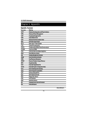
GA-7A8DRH Motherboard RCehvaispitoenr H6istAoprypendix Appendix : Acronyms Acronyms Meaning ACPI Advanced Configuration and Power Interface APM Advanced Power Management AGP Accelerated Graphics Port AMR Audio Modem Riser ACR Advanced Communications Riser BBS BIOS Boot Specification BIOS Basic Input / Output System CPU Central Processing Unit CMOS Complementary Metal Oxide Semiconductor CRIMM Continuity RIMM CNR Communication and Networking Riser DMA Direct Memory Access DMI Desktop Management Interface DIMM Dual Inline Memory Module DRM Dual Retention ...
GA-7A8DRH Motherboard RCehvaispitoenr H6istAoprypendix Appendix : Acronyms Acronyms Meaning ACPI Advanced Configuration and Power Interface APM Advanced Power Management AGP Accelerated Graphics Port AMR Audio Modem Riser ACR Advanced Communications Riser BBS BIOS Boot Specification BIOS Basic Input / Output System CPU Central Processing Unit CMOS Complementary Metal Oxide Semiconductor CRIMM Continuity RIMM CNR Communication and Networking Riser DMA Direct Memory Access DMI Desktop Management Interface DIMM Dual Inline Memory Module DRM Dual Retention ...


