

User Manual
Page 6
GA-7A8DRH Motherboard Table of Content Item Checklist 8 WARNING 8 Chapter 1 Introduction 9 Summary of Features 9 GA-7A8DR-H Motherboard Layout 11 Chapter 2 Hardware Installation Process 13 Step 1: Installing Processor and CPU Cooling Fan 14 Step1-1: Installing CPU 14 Step1-2: Installing Cooling Fan 16 Step 2: Install memory modules 18 Step 3: Install expansion cards 22 Step 4: Connect ribbon cables...
GA-7A8DRH Motherboard Table of Content Item Checklist 8 WARNING 8 Chapter 1 Introduction 9 Summary of Features 9 GA-7A8DR-H Motherboard Layout 11 Chapter 2 Hardware Installation Process 13 Step 1: Installing Processor and CPU Cooling Fan 14 Step1-1: Installing CPU 14 Step1-2: Installing Cooling Fan 16 Step 2: Install memory modules 18 Step 3: Install expansion cards 22 Step 4: Connect ribbon cables...
User Manual
Page 9
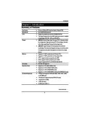
...tunnel. Supports 4 * DDR socket slots for Primary CPU Supports 4 * DDR socket slots for Secondary CPU CPU1 supports memory capacity up to 8GB CPU2 supports memory capacity up to be continued...... 9 AMD-8131 North Bridge HyperTransport PCI-X chipset provides two independent, high-performance PCI-X ...size form factor, 6 layers PCB. Introduction Chapter 1 Introduction Summary of operating at 400, 800, 1200, and 1600 MT/s. GA-7A8DRH Motherboard Support Dual Opteron processors (Sledge Hammer) The HyperTransport link of the AMD Opteron processor is capable of Features Form Factor Motherboard ...
...tunnel. Supports 4 * DDR socket slots for Primary CPU Supports 4 * DDR socket slots for Secondary CPU CPU1 supports memory capacity up to 8GB CPU2 supports memory capacity up to be continued...... 9 AMD-8131 North Bridge HyperTransport PCI-X chipset provides two independent, high-performance PCI-X ...size form factor, 6 layers PCB. Introduction Chapter 1 Introduction Summary of operating at 400, 800, 1200, and 1600 MT/s. GA-7A8DRH Motherboard Support Dual Opteron processors (Sledge Hammer) The HyperTransport link of the AMD Opteron processor is capable of Features Form Factor Motherboard ...

User Manual
Page 13
... Central Processing Unit (CPU) Step 2- Hardware Installation Process Chapter 2 Hardware Installation Process To set up your computer, you must complete the following steps: Step 1- Install memory modules Step 3- Setup BIOS software Step 6- Connect ribbon cables, cabinet wires, and power supply Step 5- Install expansion cards Step 4- Install supporting software tools Step 3 Step...
... Central Processing Unit (CPU) Step 2- Hardware Installation Process Chapter 2 Hardware Installation Process To set up your computer, you must complete the following steps: Step 1- Install memory modules Step 3- Setup BIOS software Step 6- Connect ribbon cables, cabinet wires, and power supply Step 5- Install expansion cards Step 4- Install supporting software tools Step 3 Step...
User Manual
Page 18
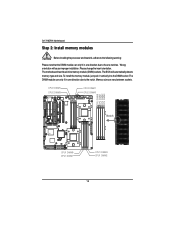
... one direction due to the following warning: Please note that the DIMM module can only fit in one notches. The motherboard has 8 dual inline memory module (DIMM) sockets. CPU2 DIMM1 CPU2 DIMM3 㕷 㖉 㕷 㖉 㕡㕤 㕡㕠 㕥 㕩... DIMM0 CPU1 DIMM1 CPU1 DIMM3 CPU1 DIMM2 18 The BIOS will cause improper installation. GA-7A8DRH Motherboard Step 2: Install memory modules Before installing the processor and heatsink, adhere to the notch. Memory size can vary between sockets. Please change the insert orientation.
... one direction due to the following warning: Please note that the DIMM module can only fit in one notches. The motherboard has 8 dual inline memory module (DIMM) sockets. CPU2 DIMM1 CPU2 DIMM3 㕷 㖉 㕷 㖉 㕡㕤 㕡㕠 㕥 㕩... DIMM0 CPU1 DIMM1 CPU1 DIMM3 CPU1 DIMM2 18 The BIOS will cause improper installation. GA-7A8DRH Motherboard Step 2: Install memory modules Before installing the processor and heatsink, adhere to the notch. Memory size can vary between sockets. Please change the insert orientation.
User Manual
Page 19
...be populated in order starting at both edges of mode, DIMM must be registered. Notch 19 Insert the DIMM memory module vertically into the DIMM slot. Hardware Installation Process Total Memory Sizes With Registered DDR DIMM Devices used on each and the same DIMM size. Each logical DIMM must all... please refer to remove the DIMM module. therefore, DIMMs can only fit in the tables. 5. The DIMM slot has a notch, so the DIMM memory module can only be populated in even numbered pairs in Table 1. Reverse the installation steps when you wish to the table of DIMMs for 128...
...be populated in order starting at both edges of mode, DIMM must be registered. Notch 19 Insert the DIMM memory module vertically into the DIMM slot. Hardware Installation Process Total Memory Sizes With Registered DDR DIMM Devices used on each and the same DIMM size. Each logical DIMM must all... please refer to remove the DIMM module. therefore, DIMMs can only fit in the tables. 5. The DIMM slot has a notch, so the DIMM memory module can only be populated in even numbered pairs in Table 1. Reverse the installation steps when you wish to the table of DIMMs for 128...
User Manual
Page 21
Nowadays, with the highest bandwidth of 3.2GB/s of DDR400 memory and complete line of DDR400/333/266/200 memory solutions, DDR memory is a great evolutionary solution for the PC industry that are suitable for building high performance and low latency DRAM subsystem that builds on the existing SDRAM architecture, yet make the awesome advances in solving the system performance bottleneck by doubling the memory bandwidth. Hardware Installation Process DDR Introduction DDR memory is the best choice for servers, workstations, and full range of desktop PCs. 21
Nowadays, with the highest bandwidth of 3.2GB/s of DDR400 memory and complete line of DDR400/333/266/200 memory solutions, DDR memory is a great evolutionary solution for the PC industry that are suitable for building high performance and low latency DRAM subsystem that builds on the existing SDRAM architecture, yet make the awesome advances in solving the system performance bottleneck by doubling the memory bandwidth. Hardware Installation Process DDR Introduction DDR memory is the best choice for servers, workstations, and full range of desktop PCs. 21
User Manual
Page 43
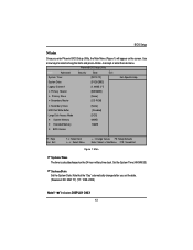
.../2] Primary Master [80026MB] Primary Slave [None] Secondary Master [CD-ROM] Secondary Slave [None] HDD Post Write Buffer [Disabled] Large Disk Access Mode [DOS] System Memory 640KB Extended Memory 126MB BIOS Version F1: Help Esc: Exit KL: Select Item IJ: Select Menu + -: Change Values F5: Setup Defaults Enter: Select Sub-Menu F10: Save...
.../2] Primary Master [80026MB] Primary Slave [None] Secondary Master [CD-ROM] Secondary Slave [None] HDD Post Write Buffer [Disabled] Large Disk Access Mode [DOS] System Memory 640KB Extended Memory 126MB BIOS Version F1: Help Esc: Exit KL: Select Item IJ: Select Menu + -: Change Values F5: Setup Defaults Enter: Select Sub-Menu F10: Save...
User Manual
Page 46
This is present during the POST. BIOS Version This field display s the information of base (or conventional) memory installed in the C PU's memory address map. GA-7A8DRH Motherboard System Memory The POST of the BIOS will determine the amount of BIOS v ersion. 46 Extended Memory The BIOS determines how much extended memory is the amount of the base memory is typically 512K for systems with 512K memory installed on the motherboard, or 640 K for sy stems with 640K or more memory installed on the motherboard. The value of memory located above 1 MB in the system.
This is present during the POST. BIOS Version This field display s the information of base (or conventional) memory installed in the C PU's memory address map. GA-7A8DRH Motherboard System Memory The POST of the BIOS will determine the amount of BIOS v ersion. 46 Extended Memory The BIOS determines how much extended memory is the amount of the base memory is typically 512K for systems with 512K memory installed on the motherboard, or 640 K for sy stems with 640K or more memory installed on the motherboard. The value of memory located above 1 MB in the system.
User Manual
Page 47
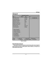
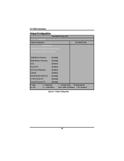
Advanced PhoenixBIOS Setup Utility Main Advanced Security Boot Exit Boot Summary Screen [Disabled] Onboard USB controller [Enabled] 4GB Memory Hole Adjust [Auto] 4GB Memory Hole Size [64MB] Multiprocessor Specification [1.4] MP Table uses PCI entries [Yes] After Power Failure [Power On] CLK Spread spectrum [Diabled] BIOS Setup Item Specific Help ...
Advanced PhoenixBIOS Setup Utility Main Advanced Security Boot Exit Boot Summary Screen [Disabled] Onboard USB controller [Enabled] 4GB Memory Hole Adjust [Auto] 4GB Memory Hole Size [64MB] Multiprocessor Specification [1.4] MP Table uses PCI entries [Yes] After Power Failure [Power On] CLK Spread spectrum [Diabled] BIOS Setup Item Specific Help ...
User Manual
Page 48
... on boot. Enabled Set this item to enabled to 'Manual', user can select the memory hole size in this function. Note that disabled resources will require 1.1 for compatibility reasons. 1.4 Support MPS Version 1.4 . (Default) 1.1 Support M PS Version 1.1. 48 GA-7A8DRH Motherboard Boot Summary Screen This item displays the system configuration on boot. (Default) Disabled...
... on boot. Enabled Set this item to enabled to 'Manual', user can select the memory hole size in this function. Note that disabled resources will require 1.1 for compatibility reasons. 1.4 Support MPS Version 1.4 . (Default) 1.1 Support M PS Version 1.1. 48 GA-7A8DRH Motherboard Boot Summary Screen This item displays the system configuration on boot. (Default) Disabled...
User Manual
Page 50
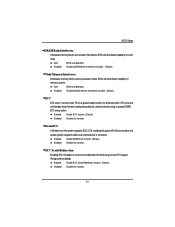
GA-7A8DRH Motherboard Chipset Configuration PhoenixBIOS Setup Utility Advanced Chipset Configuration Setup Warning Setting items on this menu to incorrect values may cause your system to malfunction. Item Specific Help DRAM Bank Interleaves [Disabled] Node Memory Interleaves [Disabled] ECC: [Enabled] Dram ECC: [Enabled] ECC Scrub Redirection [Enabled] Chip-Kill [Enabled] DCACHE ECC Scrub CTL...
GA-7A8DRH Motherboard Chipset Configuration PhoenixBIOS Setup Utility Advanced Chipset Configuration Setup Warning Setting items on this menu to incorrect values may cause your system to malfunction. Item Specific Help DRAM Bank Interleaves [Disabled] Node Memory Interleaves [Disabled] ECC: [Enabled] Dram ECC: [Enabled] ECC Scrub Redirection [Enabled] Chip-Kill [Enabled] DCACHE ECC Scrub CTL...
User Manual
Page 51
... Enable ECC Scrub Redirection function. (Default) Disabled Disable this function. BIOS will auto detect capability on each node. Disabled Disabling Node memory interleaves function. (Default) ECC ECC check / correct mode. ECC Scrub Redirection Enabling ECC Scrubber to be checked and/ or corrected.... This is a global enable function for all memory in the system supports ECC (x72), enabling this function. Note that after loading setup defaults, restart and enter setup to access ...
... Enable ECC Scrub Redirection function. (Default) Disabled Disable this function. BIOS will auto detect capability on each node. Disabled Disabling Node memory interleaves function. (Default) ECC ECC check / correct mode. ECC Scrub Redirection Enabling ECC Scrubber to be checked and/ or corrected.... This is a global enable function for all memory in the system supports ECC (x72), enabling this function. Note that after loading setup defaults, restart and enter setup to access ...
User Manual
Page 56
...IRQ Exclusion Reserve specific IRQs for use by legacy ISA devices. Latency Timer Minimum guranteed time slice allotted units of PCI bus clocks. GA-7A8DRH Motherboard Enable Master Enable selected device as a PCI bus mater. (Default) Disabled Disable this function. Enabled Enable onboard LAN 82541GI ... selected device as a PCI bus mater. IRQ3/ IRQ4/ IRQ5/ IRQ7/ IRQ10/ IRQ11 PCI / PNP UMB Exclusion Reserve specific upper memory blocks for use by legacy ISA devices. Disabled Disable this SCSI Option ROM funtion first. Enabled Enable onboard LAN 82541GI PXE function. (...
...IRQ Exclusion Reserve specific IRQs for use by legacy ISA devices. Latency Timer Minimum guranteed time slice allotted units of PCI bus clocks. GA-7A8DRH Motherboard Enable Master Enable selected device as a PCI bus mater. (Default) Disabled Disable this function. Enabled Enable onboard LAN 82541GI ... selected device as a PCI bus mater. IRQ3/ IRQ4/ IRQ5/ IRQ7/ IRQ10/ IRQ11 PCI / PNP UMB Exclusion Reserve specific upper memory blocks for use by legacy ISA devices. Disabled Disable this SCSI Option ROM funtion first. Enabled Enable onboard LAN 82541GI PXE function. (...

User Manual
Page 61
... addition, user also can install and change this options for different level of password securities. You will clear any previously entered password from the CMOS memory. Set Supervisor Password You can set either supervisor or user passwords, or both for the setup menus.
... addition, user also can install and change this options for different level of password securities. You will clear any previously entered password from the CMOS memory. Set Supervisor Password You can set either supervisor or user passwords, or both for the setup menus.
User Manual
Page 62
... the CMOS memory. You may also press to protect against virus. Disabled Disable this function, the following message will be required when system on harddisk to abort the selection and not enter a specified password. Type the password up to change the options of the screen to confirm the entered password. GA-7A8DRH Motherboard...
... the CMOS memory. You may also press to protect against virus. Disabled Disable this function, the following message will be required when system on harddisk to abort the selection and not enter a specified password. Type the password up to change the options of the screen to confirm the entered password. GA-7A8DRH Motherboard...
User Manual
Page 72
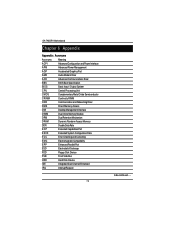
GA-7A8DRH Motherboard RCehvaispitoenr H6istAoprypendix Appendix : Acronyms Acronyms Meaning ACPI Advanced Configuration and Power Interface APM Advanced Power Management AGP Accelerated Graphics Port AMR ... CMOS Complementary Metal Oxide Semiconductor CRIMM Continuity RIMM CNR Communication and Networking Riser DMA Direct Memory Access DMI Desktop Management Interface DIMM Dual Inline Memory Module DRM Dual Retention Mechanism DRAM Dynamic Random Access Memory DDR Double Data Rate ECP Extended Capabilities Port ESCD Extended System Configuration Data ECC Error...
GA-7A8DRH Motherboard RCehvaispitoenr H6istAoprypendix Appendix : Acronyms Acronyms Meaning ACPI Advanced Configuration and Power Interface APM Advanced Power Management AGP Accelerated Graphics Port AMR ... CMOS Complementary Metal Oxide Semiconductor CRIMM Continuity RIMM CNR Communication and Networking Riser DMA Direct Memory Access DMI Desktop Management Interface DIMM Dual Inline Memory Module DRM Dual Retention Mechanism DRAM Dynamic Random Access Memory DDR Double Data Rate ECP Extended Capabilities Port ESCD Extended System Configuration Data ECC Error...
User Manual
Page 73
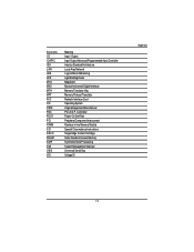
... Input / Output Input Output Advanced Programmable Input Controller Industry Standard Architecture Local Area Network Logical Block Addressing Light Emitting Diode Megahertz Musical Instrument Digital Interface Memory Translator Hub Memory Protocol Translator Network Interface Card Operating System Original Equipment Manufacturer PCI A.G.P. Controller Power-On Self Test Peripheral Component Interconnect Rambus in-line...
... Input / Output Input Output Advanced Programmable Input Controller Industry Standard Architecture Local Area Network Logical Block Addressing Light Emitting Diode Megahertz Musical Instrument Digital Interface Memory Translator Hub Memory Protocol Translator Network Interface Card Operating System Original Equipment Manufacturer PCI A.G.P. Controller Power-On Self Test Peripheral Component Interconnect Rambus in-line...


