
User Manual
Page 2
... 10 Step 2-1-1: Installing CPU 10 Step 2-1-2: Installing Heat Sink 11 2-2: Install memory modules 12 2-3: Install expansion cards 14 2-4: Connect ribbon cables, cabinet wires, and power supply 15 2-4-1 : I/O Back Panel Introduction 15 2-4-2 :Connectors & Jumper Setting Introduction 17 Chapter 3 BIOS Setup 26 Main ...28 Advanced Processor Options 31 Advanced 33 Memory Configuration ...34 PCI Configuration ...36 I/O Device Configuration 38 Advanced Chipset Control 42 Hardware Monitor ...44 Security ...47 Server ...49 System Management ...50 Console Redirection ...51 Boot ...54 Exit...
... 10 Step 2-1-1: Installing CPU 10 Step 2-1-2: Installing Heat Sink 11 2-2: Install memory modules 12 2-3: Install expansion cards 14 2-4: Connect ribbon cables, cabinet wires, and power supply 15 2-4-1 : I/O Back Panel Introduction 15 2-4-2 :Connectors & Jumper Setting Introduction 17 Chapter 3 BIOS Setup 26 Main ...28 Advanced Processor Options 31 Advanced 33 Memory Configuration ...34 PCI Configuration ...36 I/O Device Configuration 38 Advanced Chipset Control 42 Hardware Monitor ...44 Security ...47 Server ...49 System Management ...50 Console Redirection ...51 Boot ...54 Exit...
User Manual
Page 3
English Table of Content Chapter 4 Technical Reference 62 Block Diagram 62 Chapter 5 Driver Installation 63 A. XGI VGA Driver Installation 68 E. Matrix Storgae Manager Utility Installation 69 F. Broadcom LAN Driver Installation 65 C. Intel Chipset Software Installation Utilities 63 B. Intel RAID Driver Installation 67 D. DirectX 9.0C Driver Installation 71 Chapter 6 Appendix 72 Acronyms ...72 3
English Table of Content Chapter 4 Technical Reference 62 Block Diagram 62 Chapter 5 Driver Installation 63 A. XGI VGA Driver Installation 68 E. Matrix Storgae Manager Utility Installation 69 F. Broadcom LAN Driver Installation 65 C. Intel Chipset Software Installation Utilities 63 B. Intel RAID Driver Installation 67 D. DirectX 9.0C Driver Installation 71 Chapter 6 Appendix 72 Acronyms ...72 3
User Manual
Page 4
... may be near by the edges and try not touch the IC chips, leads or connectors, or other components. 4. Hold components by the hole. English GA-7VCSV-RH Motherboard Item Checklist The GA-7VCSV-RH motherboard IDE (ATA100 ) cable x 1 / Floppy cable x 1 CD for motherboard driver & utility GA-7VCSV-RH Quick Reference Guide Serial ATA cable x 6 Serial ATA power cable x 6 I/O Shield Kit WARNING! Use a grounded wrist strap before you may be careful of your hands...
... may be near by the edges and try not touch the IC chips, leads or connectors, or other components. 4. Hold components by the hole. English GA-7VCSV-RH Motherboard Item Checklist The GA-7VCSV-RH motherboard IDE (ATA100 ) cable x 1 / Floppy cable x 1 CD for motherboard driver & utility GA-7VCSV-RH Quick Reference Guide Serial ATA cable x 6 Serial ATA power cable x 6 I/O Shield Kit WARNING! Use a grounded wrist strap before you may be careful of your hands...

User Manual
Page 5
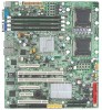
...Dual Channel memory bus Fully Buffered DIMM (FBD) 533/667MHz Support 512MB, 1GB, 2GB, and 4GB memory Single-bit Errors Correction, Multiple-bit Errors Detection ITE IT8718 Super I/O Supports 1 PCI slots 32-Bit/33MHz (5V) Supports 2 PCI-X slots 64-Bit/100~133MHz Supports 1 PCI-E x1 (in x4 slot) Supports 1 PCI-E x4 (in x8 slot) Supports 1 PCI-E x8 slot Intel® 6321ESB built in SATA RAID 0,1,5, 10 (Windows Only) Supports 6 SATA/SATAII devices 1 ATA 100 connector 1 Floppy port supports 720K, 1.44M and 2.88M bytes. 2 PS/2 connectors 2 Serial port (COM; 1 by cable) 8 x USB 2.0 (4 by cable) 1 VGA...
...Dual Channel memory bus Fully Buffered DIMM (FBD) 533/667MHz Support 512MB, 1GB, 2GB, and 4GB memory Single-bit Errors Correction, Multiple-bit Errors Detection ITE IT8718 Super I/O Supports 1 PCI slots 32-Bit/33MHz (5V) Supports 2 PCI-X slots 64-Bit/100~133MHz Supports 1 PCI-E x1 (in x4 slot) Supports 1 PCI-E x4 (in x8 slot) Supports 1 PCI-E x8 slot Intel® 6321ESB built in SATA RAID 0,1,5, 10 (Windows Only) Supports 6 SATA/SATAII devices 1 ATA 100 connector 1 Floppy port supports 720K, 1.44M and 2.88M bytes. 2 PS/2 connectors 2 Serial port (COM; 1 by cable) 8 x USB 2.0 (4 by cable) 1 VGA...

User Manual
Page 6
... SDRAM Dual Broadcom® 5789 Gigabit Ethernet controllers Hardware Monitor BIOS Additional Features Winbond 83792G controller Enhanced features with CPU Vcore, VCC3 (3.3V), VCC5V, VBAT3V, CPU Motherboard Temperature System Voltage Detect CPU/System Fan Revolution Detect CPU shutdown when overheat Phoenix BIOS on 8Mb flash ROM PS/2 Mouse wake up from S1 under Windows Operating System COM Port wake up Supports S1, S4, S5 under Windows Operating System Wake on LAN (WOL) AC Recovery Supports Console Redirection Supports 4-pin Fan controller 6
... SDRAM Dual Broadcom® 5789 Gigabit Ethernet controllers Hardware Monitor BIOS Additional Features Winbond 83792G controller Enhanced features with CPU Vcore, VCC3 (3.3V), VCC5V, VBAT3V, CPU Motherboard Temperature System Voltage Detect CPU/System Fan Revolution Detect CPU shutdown when overheat Phoenix BIOS on 8Mb flash ROM PS/2 Mouse wake up from S1 under Windows Operating System COM Port wake up Supports S1, S4, S5 under Windows Operating System Wake on LAN (WOL) AC Recovery Supports Console Redirection Supports 4-pin Fan controller 6
User Manual
Page 10
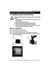
... replace the plastic covering and push the metal lever back into the socket. 3. If you do not match the CPU socket Pin 1 and CPU cut edge well, it will overheat without the heatsink and/or fan, resulting in one orientation. Step 4 Once the CPU is supported by the motherboard. 5. The CPU only fits in permanent irreparable damage. 2. The processor will cause improper installation. Step 2 Remove...
... replace the plastic covering and push the metal lever back into the socket. 3. If you do not match the CPU socket Pin 1 and CPU cut edge well, it will overheat without the heatsink and/or fan, resulting in one orientation. Step 4 Once the CPU is supported by the motherboard. 5. The CPU only fits in permanent irreparable damage. 2. The processor will cause improper installation. Step 2 Remove...
User Manual
Page 17
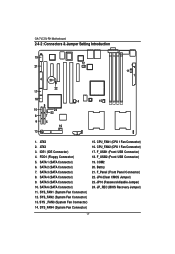
IDE1 (IDE Connector) 4. SYS_FAN1 (System Fan Connector) 12. SYS_FAN2 (System Fan Connector) 13. F_USB2 (Front USB Connector) 19. ATX3 3. SATA 2 (SATA Connector) 7. SATA 4 (SATA Connector) 9. SYS_FAN4 (System Fan Connector) 15. FDD1 (Floppy Connector) 5. SATA 5 (SATA Connector) 10. SATA 6 (SATA Connector) 11. CPU_FAN2 (CPU 1 Fan Connector) 17. JP6 (Clear CMOS Jumper) 23. JP_REC (BIOS Recovery Jumper) 17 SATA 3 (SATA Connector) 8. F_USB1 (Front USB Connector) 18. F_Panel (Front Panel Connector) 22. JP10 (Password disable Jumper) 24. GA-7VCSV-RH Motherboard ...
IDE1 (IDE Connector) 4. SYS_FAN1 (System Fan Connector) 12. SYS_FAN2 (System Fan Connector) 13. F_USB2 (Front USB Connector) 19. ATX3 3. SATA 2 (SATA Connector) 7. SATA 4 (SATA Connector) 9. SYS_FAN4 (System Fan Connector) 15. FDD1 (Floppy Connector) 5. SATA 5 (SATA Connector) 10. SATA 6 (SATA Connector) 11. CPU_FAN2 (CPU 1 Fan Connector) 17. JP6 (Clear CMOS Jumper) 23. JP_REC (BIOS Recovery Jumper) 17 SATA 3 (SATA Connector) 8. F_USB1 (Front USB Connector) 18. F_Panel (Front Panel Connector) 22. JP10 (Password disable Jumper) 24. GA-7VCSV-RH Motherboard ...
User Manual
Page 18
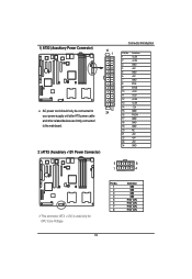
1) ATX2 (Auxukiary Power Connector) 13 1 AC power cord should only be connected to your power supply unit after ATX power cable and other related devices are firmly connected to the mainboard. 12 24 2 ) ATX3 (Auxukiary +12V Power Connector) Connector Introduction PIN No. 1 2 3 4 5... 6 7 8 9 10 11 12 13 14 15 16 17 18 19 20 21 22 23 24 Definition +3.3V +3.3V GND +5V GND +5V GND POK 5VSB +12V +12V +3.3V +3.3V -12V GND PSON GND GND GND NC +5V +5V +5V GND 5 8 1 4 This connector (ATX +12V) is used only for CPU Core Voltage. 18 Pin...
1) ATX2 (Auxukiary Power Connector) 13 1 AC power cord should only be connected to your power supply unit after ATX power cable and other related devices are firmly connected to the mainboard. 12 24 2 ) ATX3 (Auxukiary +12V Power Connector) Connector Introduction PIN No. 1 2 3 4 5... 6 7 8 9 10 11 12 13 14 15 16 17 18 19 20 21 22 23 24 Definition +3.3V +3.3V GND +5V GND +5V GND POK 5VSB +12V +12V +3.3V +3.3V -12V GND PSON GND GND GND NC +5V +5V +5V GND 5 8 1 4 This connector (ATX +12V) is used only for CPU Core Voltage. 18 Pin...
User Manual
Page 20
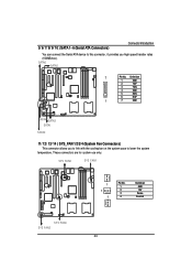
.../ 12/ 13/ 14 ) SYS_FAN 1/2/3/4 (System Fan Connectors) This connector allows you high speed transfer rates (150MB/sec). SYS FAN2 SYS FAN1 1 1 1 Pin No. 1 2 3 4 Definition GND 12V Sense Control SYS FAN4 SYS FAN3 20 5/ 6/ 7/ 8/ 9/ 10 ) SATA 1~6 (Serial ATA Connectors) Connector Introduction You can connect the Serial ATA device to this connector, it provides you to link with the cooling fan on the system case to lower the system...
.../ 12/ 13/ 14 ) SYS_FAN 1/2/3/4 (System Fan Connectors) This connector allows you high speed transfer rates (150MB/sec). SYS FAN2 SYS FAN1 1 1 1 Pin No. 1 2 3 4 Definition GND 12V Sense Control SYS FAN4 SYS FAN3 20 5/ 6/ 7/ 8/ 9/ 10 ) SATA 1~6 (Serial ATA Connectors) Connector Introduction You can connect the Serial ATA device to this connector, it provides you to link with the cooling fan on the system case to lower the system...

User Manual
Page 21
... prevent the CPU from running under abnormal condition or damaged by overheating.The CPU fan connector supports Max. F_USB1 12 9 10 Pin No. 1 2 3 4 5 6 7 8 9 10 Definition Power Power USB DxUSB DyUSB Dx+ USB Dy+ GND GND Key Pin NC F_USB2 21 Check the pin assignment carefully while you connect the front USB cable, incorrect connection between the cable and connector will make the device unable to 1A . current up to work or even...
... prevent the CPU from running under abnormal condition or damaged by overheating.The CPU fan connector supports Max. F_USB1 12 9 10 Pin No. 1 2 3 4 5 6 7 8 9 10 Definition Power Power USB DxUSB DyUSB Dx+ USB Dy+ GND GND Key Pin NC F_USB2 21 Check the pin assignment carefully while you connect the front USB cable, incorrect connection between the cable and connector will make the device unable to 1A . current up to work or even...
User Manual
Page 23
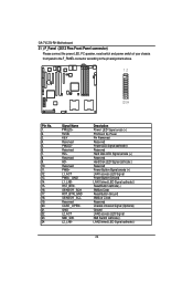
..._GND L1_LNKRST_BTNSENSOR_SDA RST_BTN_GND SENSOR_SCL Reserved CASE_OPENGND L2_ACT NMI_SWL2_LNK- Description Power LED Signal anode (+) P5VStand By Power Pin Removed Reserved Power LED Signal cathode(-) Reserved Hard Disk LED Signal anode (+) Reserved Hard Disk LED Signal cathode(-) Reserved Power Button Signal anode (+) LAN1 access LED Signal Power Button Ground LAN1 linked LED Signal cathode(-) Reset Button cathode(-) SMBus Data Reset Button Ground SMBus Clock Reserved Chassis intrusion Signal (Optional) Ground LAN2 access LED Signal NMI Switch cathode(-) LAN2 linked LED Signal cathode(-) 23
..._GND L1_LNKRST_BTNSENSOR_SDA RST_BTN_GND SENSOR_SCL Reserved CASE_OPENGND L2_ACT NMI_SWL2_LNK- Description Power LED Signal anode (+) P5VStand By Power Pin Removed Reserved Power LED Signal cathode(-) Reserved Hard Disk LED Signal anode (+) Reserved Hard Disk LED Signal cathode(-) Reserved Power Button Signal anode (+) LAN1 access LED Signal Power Button Ground LAN1 linked LED Signal cathode(-) Reset Button cathode(-) SMBus Data Reset Button Ground SMBus Clock Reserved Chassis intrusion Signal (Optional) Ground LAN2 access LED Signal NMI Switch cathode(-) LAN2 linked LED Signal cathode(-) 23
User Manual
Page 26
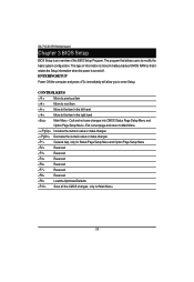
... or make changes Decrease the numeric value or make changes General help, only for Status Page Setup Menu and Option Page Setup Menu Reserved Reserved Reserved Reserved Reserved Reserved Load the Optimized Defaults Save all the CMOS changes, only for Main Menu 26 CONTROL KEYS Move to previous item Move to next item Move to the item in the right hand Main Menu - GA-7VCSV-RH Motherboard Chapter 3 BIOS Setup BIOS Setup is turned off.
... or make changes Decrease the numeric value or make changes General help, only for Status Page Setup Menu and Option Page Setup Menu Reserved Reserved Reserved Reserved Reserved Reserved Load the Optimized Defaults Save all the CMOS changes, only for Main Menu 26 CONTROL KEYS Move to previous item Move to next item Move to the item in the right hand Main Menu - GA-7VCSV-RH Motherboard Chapter 3 BIOS Setup BIOS Setup is turned off.
User Manual
Page 29
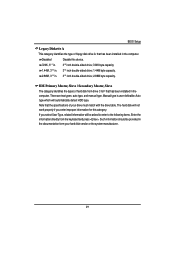
... the types of hard disk from the keyboard and press . There are two types: auto type, and manual type. If you enter improper information for this device. 720K, 31/2 in. 31/2 inch double-sided drive; 720K byte capacity 1.44M, 31/2 in. 31/2 inch double-sided drive; 1.44M byte capacity. 2.88M, 31/2 in the computer. BIOS Setup Legacy Diskette A This category identifies the type of floppy disk drive A that has been installed...
... the types of hard disk from the keyboard and press . There are two types: auto type, and manual type. If you enter improper information for this device. 720K, 31/2 in. 31/2 inch double-sided drive; 720K byte capacity 1.44M, 31/2 in. 31/2 inch double-sided drive; 1.44M byte capacity. 2.88M, 31/2 in the computer. BIOS Setup Legacy Diskette A This category identifies the type of floppy disk drive A that has been installed...
User Manual
Page 30
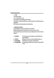
... Mode. ATAPI Removable: Removable disk drive is installed here. Multi-Sector Transfer This field displays the information of the device in the specific IDE channel support LBA Mode. Disabled: The data transfer from and to the device occurs one sector at a time if the device supports it. LBA Mode 32-Bit I/O Transfer Mode Ultra DMA Mode This field shows if the device type in the specific IDE channel. 30 Enable this function to set all HDD parameters automatically. GA-7VCSV-RH Motherboard TYPE...
... Mode. ATAPI Removable: Removable disk drive is installed here. Multi-Sector Transfer This field displays the information of the device in the specific IDE channel support LBA Mode. Disabled: The data transfer from and to the device occurs one sector at a time if the device supports it. LBA Mode 32-Bit I/O Transfer Mode Ultra DMA Mode This field shows if the device type in the specific IDE channel. 30 Enable this function to set all HDD parameters automatically. GA-7VCSV-RH Motherboard TYPE...
User Manual
Page 39
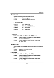
.... Enabled Enable USB controller. (Default value) Disabled Disbale this option. Enabled 'Enabled' forces the PS/2 mouse port to be enabled regardless if a mouse is present. (Default value) Disabled 'Disabled' prevents any installed PS/2 mouse from functioning, but frees up IRQ12. 39 PS/2 Mouse Set this option 'Enabled' to allow BIOS support for a PS/2 - BIOS Setup PS/2 Mouse Set this option 'Enabled' to allow BIOS support for a PS/2 - Serial Port B This allows users to configure serial prot B by setting item to the desired value. Enabled Enable the configuration...
.... Enabled Enable USB controller. (Default value) Disabled Disbale this option. Enabled 'Enabled' forces the PS/2 mouse port to be enabled regardless if a mouse is present. (Default value) Disabled 'Disabled' prevents any installed PS/2 mouse from functioning, but frees up IRQ12. 39 PS/2 Mouse Set this option 'Enabled' to allow BIOS support for a PS/2 - BIOS Setup PS/2 Mouse Set this option 'Enabled' to allow BIOS support for a PS/2 - Serial Port B This allows users to configure serial prot B by setting item to the desired value. Enabled Enable the configuration...
User Manual
Page 65
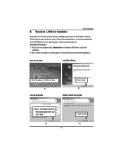
... LAN Driver" to start and show a series of installation wizards appear. Installation Procedures: 1. Auto Run window Installation Wizard 1.Click "Broadcom LAN Driver" item. (1) License Agreement 2.Click "Next". (2) Ready to install the applications. Select "I accept the terms in "My computer", and execute the setup.exe. Follow up the wizards to install the program 3. Broadcom LAN Driver Installation Driver Installation Insert the driver CD-title that came with your motherboard into your CD-ROM driver...
... LAN Driver" to start and show a series of installation wizards appear. Installation Procedures: 1. Auto Run window Installation Wizard 1.Click "Broadcom LAN Driver" item. (1) License Agreement 2.Click "Next". (2) Ready to install the applications. Select "I accept the terms in "My computer", and execute the setup.exe. Follow up the wizards to install the program 3. Broadcom LAN Driver Installation Driver Installation Insert the driver CD-title that came with your motherboard into your CD-ROM driver...

User Manual
Page 68
... setup.exe. XGI VGA Driver Installation Insert the driver CD-title that came with your motherboard into your CD-ROM driver, the driver CD-title will auto start the installation. 2. Installationcompleted. The CD auto run program starts, Double click on "Display Driver" item. Click "Finish" to start and show a series of installation wizards appear. Follow up the wizards to restart your system. (3) (4) 68 GA-7VCSV-RH Motherboard D. Setup completed, click "Finish" to install the drivers...
... setup.exe. XGI VGA Driver Installation Insert the driver CD-title that came with your motherboard into your CD-ROM driver, the driver CD-title will auto start the installation. 2. Installationcompleted. The CD auto run program starts, Double click on "Display Driver" item. Click "Finish" to start and show a series of installation wizards appear. Follow up the wizards to restart your system. (3) (4) 68 GA-7VCSV-RH Motherboard D. Setup completed, click "Finish" to install the drivers...

User Manual
Page 69
... CD-ROM driver, the driver CD-title will auto start and show the installation guide. Auto Run window Setup Wizard 1. Click "Yes". (3) (4) 69 Follow up the wizards to install the drivers. 3.Setup completed, click "Finish" to start the installation . 2. Matrix Storgae Manager Utility Installation Insert the driver CD-title that came with your motherboard into your computer. Click "Next". (2) License Agreement 3. Installation Procedures: 1. Driver Installation E. If not, please double click the CD-ROM device...
... CD-ROM driver, the driver CD-title will auto start and show the installation guide. Auto Run window Setup Wizard 1. Click "Yes". (3) (4) 69 Follow up the wizards to install the drivers. 3.Setup completed, click "Finish" to start the installation . 2. Matrix Storgae Manager Utility Installation Insert the driver CD-title that came with your motherboard into your computer. Click "Next". (2) License Agreement 3. Installation Procedures: 1. Driver Installation E. If not, please double click the CD-ROM device...

User Manual
Page 71
... wizards to install the drivers. 3.Setup completed, click "Finish" to start the installation. 2. Then, a series of installation wizards appear. Click "Finish". Installation Procedures: 1. If not, please double click the CD-ROM device icon in "My computer", and execute the setup.exe. Auto Run windows License Agreement 1.Click "DirectX 9.0C Driver" item (1) Starting Installaiton 2. F. DirectX 9.0C Driver Installation Driver Installation Insert the driver CD-title that came with your motherboard into your...
... wizards to install the drivers. 3.Setup completed, click "Finish" to start the installation. 2. Then, a series of installation wizards appear. Click "Finish". Installation Procedures: 1. If not, please double click the CD-ROM device icon in "My computer", and execute the setup.exe. Auto Run windows License Agreement 1.Click "DirectX 9.0C Driver" item (1) Starting Installaiton 2. F. DirectX 9.0C Driver Installation Driver Installation Insert the driver CD-title that came with your motherboard into your...

User Manual
Page 72
GA-7VCSV-RH Motherboard RCehvaispitoenr H6istAoprypendix Acronyms Acronyms Meaning ACPI Advanced Configuration and Power Interface APM Advanced Power Management AGP Accelerated Graphics Port AMR Audio Modem Riser ACR Advanced Communications Riser BBS BIOS Boot Specification BIOS Basic Input / Output System CPU Central Processing Unit CMOS Complementary Metal Oxide Semiconductor CRIMM Continuity RIMM CNR Communication and Networking Riser DMA Direct Memory Access DMI Desktop Management Interface DIMM Dual Inline Memory Module DRM Dual Retention Mechanism...
GA-7VCSV-RH Motherboard RCehvaispitoenr H6istAoprypendix Acronyms Acronyms Meaning ACPI Advanced Configuration and Power Interface APM Advanced Power Management AGP Accelerated Graphics Port AMR Audio Modem Riser ACR Advanced Communications Riser BBS BIOS Boot Specification BIOS Basic Input / Output System CPU Central Processing Unit CMOS Complementary Metal Oxide Semiconductor CRIMM Continuity RIMM CNR Communication and Networking Riser DMA Direct Memory Access DMI Desktop Management Interface DIMM Dual Inline Memory Module DRM Dual Retention Mechanism...


