User Manual
Page 1
GA-7VCSV-RH Dual Xeon Processor Motherboard USER'S MANUAL XeonTM Processor Motherboard Rev. 2001
GA-7VCSV-RH Dual Xeon Processor Motherboard USER'S MANUAL XeonTM Processor Motherboard Rev. 2001

User Manual
Page 2
... Table of Content Item Checklist 4 WARNING 4 Chapter 1 Introduction 5 1.1 Features Summary 5 1.2 GA-7VCSV-RH Motherboard Components 8 Chapter 2 Hardware Installation Process 10 2-1: Installing Processor and CPU Haet Sink 10 Step 2-1-1: Installing CPU 10 Step 2-1-2: Installing Heat Sink 11 2-2: Install memory ...
... Table of Content Item Checklist 4 WARNING 4 Chapter 1 Introduction 5 1.1 Features Summary 5 1.2 GA-7VCSV-RH Motherboard Components 8 Chapter 2 Hardware Installation Process 10 2-1: Installing Processor and CPU Haet Sink 10 Step 2-1-1: Installing CPU 10 Step 2-1-2: Installing Heat Sink 11 2-2: Install memory ...
User Manual
Page 4
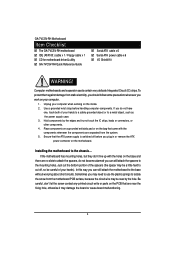
... contact any printed circuit write or parts on the inside. 2. Ensure that are separated from the system. 5. English GA-7VCSV-RH Motherboard Item Checklist The GA-7VCSV-RH motherboard IDE (ATA100 ) cable x 1 / Floppy cable x 1 CD for motherboard driver & utility GA-7VCSV-RH Quick Reference Guide Serial ATA cable x 6 Serial ATA power cable x 6 I/O Shield Kit WARNING! Sometimes you work on...
... contact any printed circuit write or parts on the inside. 2. Ensure that are separated from the system. 5. English GA-7VCSV-RH Motherboard Item Checklist The GA-7VCSV-RH motherboard IDE (ATA100 ) cable x 1 / Floppy cable x 1 CD for motherboard driver & utility GA-7VCSV-RH Quick Reference Guide Serial ATA cable x 6 Serial ATA power cable x 6 I/O Shield Kit WARNING! Sometimes you work on...

User Manual
Page 6
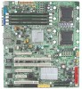
English GA-7VCSV-RH Motherboard On-Board Graphic On-Board LAN XGI Volari Z7 with 16MB DDR SDRAM Dual Broadcom® 5789 Gigabit Ethernet controllers Hardware Monitor BIOS Additional ...
English GA-7VCSV-RH Motherboard On-Board Graphic On-Board LAN XGI Volari Z7 with 16MB DDR SDRAM Dual Broadcom® 5789 Gigabit Ethernet controllers Hardware Monitor BIOS Additional ...

User Manual
Page 11
Step 2. Attach the power connector of Secure the heatsink supporting-base onto the the installed CPU. English GA-7VCSV-RH Motherboard Step 2-1-2: Installing Heat Sink Step 1. Please apply heatsink paste on the surface of the heatsink to the CPU fan header located on the mainboard. Step 3. CPU socket on the motherboard. 11
Step 2. Attach the power connector of Secure the heatsink supporting-base onto the the installed CPU. English GA-7VCSV-RH Motherboard Step 2-1-2: Installing Heat Sink Step 1. Please apply heatsink paste on the surface of the heatsink to the CPU fan header located on the mainboard. Step 3. CPU socket on the motherboard. 11
User Manual
Page 12
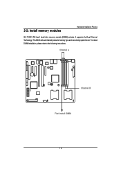
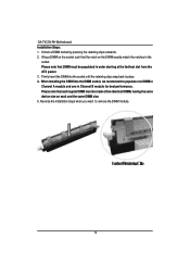
It supports the Dual Channel Technology. Channel A Channel B First Install DIMM 12 The BIOS will automatically detects memory type and size during system boot. For detail DIMM installation, please refer to the following instructions. 2-2: Install memory modules Hardware Installation Process GA-7VCSV-RH has 4 dual inline memory module (DIMM) sokcets.
It supports the Dual Channel Technology. Channel A Channel B First Install DIMM 12 The BIOS will automatically detects memory type and size during system boot. For detail DIMM installation, please refer to the following instructions. 2-2: Install memory modules Hardware Installation Process GA-7VCSV-RH has 4 dual inline memory module (DIMM) sokcets.
User Manual
Page 13
... in Channel B module for best performance. Aling a DIMM on the socket such that the notch on each logical DIMM must be populated in place. 4. English GA-7VCSV-RH Motherboard Installation Steps: 1. Unlock a DIMM socket by pressing the retaining clips outwards. 2.
... in Channel B module for best performance. Aling a DIMM on the socket such that the notch on each logical DIMM must be populated in place. 4. English GA-7VCSV-RH Motherboard Installation Steps: 1. Unlock a DIMM socket by pressing the retaining clips outwards. 2.
User Manual
Page 15
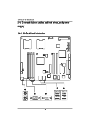
English GA-7VCSV-RH Motherboard 2-4: Connect ribbon cables, cabinet wires, and power supply 2-4-1 : I/O Back Panel Introduction 15
English GA-7VCSV-RH Motherboard 2-4: Connect ribbon cables, cabinet wires, and power supply 2-4-1 : I/O Back Panel Introduction 15
User Manual
Page 17
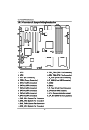
... CMOS Jumper) 23. IDE1 (IDE Connector) 4. SATA 6 (SATA Connector) 11. SYS_FAN2 (System Fan Connector) 13. SYS_FAN4 (System Fan Connector) 15. JP10 (Password disable Jumper) 24. GA-7VCSV-RH Motherboard 2-4-2 :Connectors & Jumper Setting Introduction English 19 12 21 4 20 11 1 22 17 18 14 15 9 10 24 23 8 7 6 5 16 13 3 2 1. COM2 20. SATA 4 (SATA...
... CMOS Jumper) 23. IDE1 (IDE Connector) 4. SATA 6 (SATA Connector) 11. SYS_FAN2 (System Fan Connector) 13. SYS_FAN4 (System Fan Connector) 15. JP10 (Password disable Jumper) 24. GA-7VCSV-RH Motherboard 2-4-2 :Connectors & Jumper Setting Introduction English 19 12 21 4 20 11 1 22 17 18 14 15 9 10 24 23 8 7 6 5 16 13 3 2 1. COM2 20. SATA 4 (SATA...
User Manual
Page 19
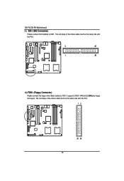
The red stripe of the ribbon cable must be the same side with the Pin1. 12 33 34 19 It supports 720K,1.44M and 2.88Mbytes floppy disk types. English GA-7VCSV-RH Motherboard 3 ) IDE1 (IDE Connector) Please connect first harddisk to FDD. The red stripe of the ribbon cable must be the same side with the Pin1. 2 40 1 39 4 ) FDD1 (Floppy Connector) Please connect the floppy drive ribbon cables to IDE1.
The red stripe of the ribbon cable must be the same side with the Pin1. 12 33 34 19 It supports 720K,1.44M and 2.88Mbytes floppy disk types. English GA-7VCSV-RH Motherboard 3 ) IDE1 (IDE Connector) Please connect first harddisk to FDD. The red stripe of the ribbon cable must be the same side with the Pin1. 2 40 1 39 4 ) FDD1 (Floppy Connector) Please connect the floppy drive ribbon cables to IDE1.

User Manual
Page 21
... CPU from running under abnormal condition or damaged by overheating.The CPU fan connector supports Max. current up to work or even damage it. English GA-7VCSV-RH Motherboard 15/ 16 ) CPU1/2_FAN (CPU Fan Connectors) Please note, a proper installation of the front USB connector.
... CPU from running under abnormal condition or damaged by overheating.The CPU fan connector supports Max. current up to work or even damage it. English GA-7VCSV-RH Motherboard 15/ 16 ) CPU1/2_FAN (CPU Fan Connectors) Please note, a proper installation of the front USB connector.
User Manual
Page 23
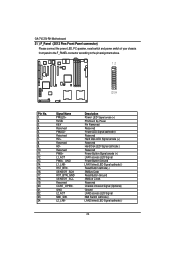
... Signal cathode(-) 23 Signal Name PWLED+ 5VSB KEY Reserved PWLEDReserved HD+ Reserved HDReserved PWB+ L1_ACT PWB+_GND L1_LNKRST_BTNSENSOR_SDA RST_BTN_GND SENSOR_SCL Reserved CASE_OPENGND L2_ACT NMI_SWL2_LNK- English GA-7VCSV-RH Motherboard 21 ) F_Panel (2X12 Pins Front Panel connector) Please connect the power LED, PC speaker, reset switch and power switch of your chassis front panel...
... Signal cathode(-) 23 Signal Name PWLED+ 5VSB KEY Reserved PWLEDReserved HD+ Reserved HDReserved PWB+ L1_ACT PWB+_GND L1_LNKRST_BTNSENSOR_SDA RST_BTN_GND SENSOR_SCL Reserved CASE_OPENGND L2_ACT NMI_SWL2_LNK- English GA-7VCSV-RH Motherboard 21 ) F_Panel (2X12 Pins Front Panel connector) Please connect the power LED, PC speaker, reset switch and power switch of your chassis front panel...
User Manual
Page 25
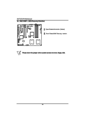
English GA-7VCSV-RH Motherboard 25 ) RECOVERY ( BIOS Recovery Function) Open: Disable this function. (Default) Short: Enable BIOS Recovery function Please short the jumper when system access recovery floppy disk. 25
English GA-7VCSV-RH Motherboard 25 ) RECOVERY ( BIOS Recovery Function) Open: Disable this function. (Default) Short: Enable BIOS Recovery function Please short the jumper when system access recovery floppy disk. 25
User Manual
Page 26
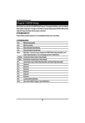
GA-7VCSV-RH Motherboard Chapter 3 BIOS Setup BIOS Setup is an overview of information is turned off. The program that it retains the Setup information when the power ...
GA-7VCSV-RH Motherboard Chapter 3 BIOS Setup BIOS Setup is an overview of information is turned off. The program that it retains the Setup information when the power ...
User Manual
Page 28
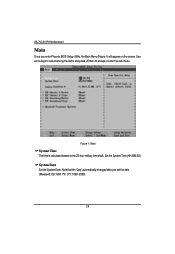
Note that the "Day" automatically changed after you enter Phoenix BIOS Setup Utility, the Main Menu (Figure 1) will appear on the 24-hour military time clock. Figure 1: Main System Time The time is calculated based on the screen. Use arrow keys to select among the items and press to accept or enter the sub-menu. Set the System Time (HH:MM:SS) System Date Set the System Date. GA-7VCSV-RH Motherboard Main Once you set the date. (Weekend: DD: MM: YY) (YY: 1099~2099) 28
Note that the "Day" automatically changed after you enter Phoenix BIOS Setup Utility, the Main Menu (Figure 1) will appear on the 24-hour military time clock. Figure 1: Main System Time The time is calculated based on the screen. Use arrow keys to select among the items and press to accept or enter the sub-menu. Set the System Time (HH:MM:SS) System Date Set the System Date. GA-7VCSV-RH Motherboard Main Once you set the date. (Weekend: DD: MM: YY) (YY: 1099~2099) 28
User Manual
Page 30
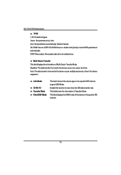
GA-7VCSV-RH Motherboard TYPE 1-39: Predefined types. Users: Set parameters by User. Multi-Sector Transfer This field displays the information of the device in the specific IDE ...
GA-7VCSV-RH Motherboard TYPE 1-39: Predefined types. Users: Set parameters by User. Multi-Sector Transfer This field displays the information of the device in the specific IDE ...
User Manual
Page 32
Protection Enabled Enable No Execute Mode Memory Protection function. (Default value) Disabled Disables No Execute Mode Memory Protection function. 32 GA-7VCSV-RH Motherboard Hyper Threading Enabled Disabled Enables Hyper-Threading Technology Feature when using Windows XP and Linux 2.4x operating systems that are optimized for HyperThreading technology. (...
Protection Enabled Enable No Execute Mode Memory Protection function. (Default value) Disabled Disables No Execute Mode Memory Protection function. 32 GA-7VCSV-RH Motherboard Hyper Threading Enabled Disabled Enables Hyper-Threading Technology Feature when using Windows XP and Linux 2.4x operating systems that are optimized for HyperThreading technology. (...
User Manual
Page 34
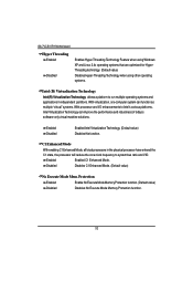
Save the changes and restart system. After rebooting system, the Memory Reset item will clear the memory error status. Memory Reset Yes No Select 'Yes', system will set to 'No' automatically. Disable this function. (Default value) Extend RAM Step Enabled Disabled Enable test extended memroy process. GA-7VCSV-RH Motherboard Memory Configuration Figure 2-1: Memory Configuration System Memory/Extended Memory/DIMMGroup 1~8 Status These category is display-only which is determined by POST (Power On Self Test) of the BIOS. Disable this function. (Default value) 34
Save the changes and restart system. After rebooting system, the Memory Reset item will clear the memory error status. Memory Reset Yes No Select 'Yes', system will set to 'No' automatically. Disable this function. (Default value) Extend RAM Step Enabled Disabled Enable test extended memroy process. GA-7VCSV-RH Motherboard Memory Configuration Figure 2-1: Memory Configuration System Memory/Extended Memory/DIMMGroup 1~8 Status These category is display-only which is determined by POST (Power On Self Test) of the BIOS. Disable this function. (Default value) 34
User Manual
Page 36
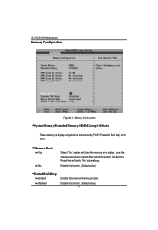
LAN2 Option ROM Scan Enabled Enable onboard LAN2 device and initialize device expansion ROM. (Default value) Disabled Disable this function. GA-7VCSV-RH Motherboard PCI Configuration Figure 2-2: PCI Configuration Embedded NIC LAN 1 Option ROM Scan Enabled Enable onboard LAN1 device and initialize device expansion ROM. (Default value) Disabled Disable this function. 36
LAN2 Option ROM Scan Enabled Enable onboard LAN2 device and initialize device expansion ROM. (Default value) Disabled Disable this function. GA-7VCSV-RH Motherboard PCI Configuration Figure 2-2: PCI Configuration Embedded NIC LAN 1 Option ROM Scan Enabled Enable onboard LAN1 device and initialize device expansion ROM. (Default value) Disabled Disable this function. 36
User Manual
Page 37
GA-7VCSV-RH Motherboard PCI Slot 1/2/3/4/5/6 Option ROM Enabled Disabled Enableing this item to initialize device expansion ROM. (Defualt value) Disable this function. 37
GA-7VCSV-RH Motherboard PCI Slot 1/2/3/4/5/6 Option ROM Enabled Disabled Enableing this item to initialize device expansion ROM. (Defualt value) Disable this function. 37


