
Manual
Page 1
GA-8I915G-MF GA-8I915GM GA-8I915GM-G Intel® Pentium® 4 LGA775 Processor Motherboard User's Manual Rev. 2203 12ME-8I915GMF-2203 * The WEEE marking on the product indicates this product must not be disposed of with user's other household waste and must be handed over to a designated collection point for the recycling of waste electrical and electronic equipment!! * The WEEE marking applies only in European Union's member states.
GA-8I915G-MF GA-8I915GM GA-8I915GM-G Intel® Pentium® 4 LGA775 Processor Motherboard User's Manual Rev. 2203 12ME-8I915GMF-2203 * The WEEE marking on the product indicates this product must not be disposed of with user's other household waste and must be handed over to a designated collection point for the recycling of waste electrical and electronic equipment!! * The WEEE marking applies only in European Union's member states.
Manual
Page 2
Motherboard GA-8I915G-MF Jun. 11, 2004 Motherboard GA-8I915G-MF Jun. 11, 2004
Motherboard GA-8I915G-MF Jun. 11, 2004 Motherboard GA-8I915G-MF Jun. 11, 2004

Manual
Page 4
Table of Content GA-8I915G-MF Motherboard Layout 6 Block Diagram ...7 Chapter 1 Hardware Installation 9 1-1 Considerations Prior to Installation 9 1-2 Feature Summary 10 1-3 Installation of the CPU and Heatsink 12 1-3-1 Installation of the CPU 12 1-3-2 ...
Table of Content GA-8I915G-MF Motherboard Layout 6 Block Diagram ...7 Chapter 1 Hardware Installation 9 1-1 Considerations Prior to Installation 9 1-2 Feature Summary 10 1-3 Installation of the CPU and Heatsink 12 1-3-1 Installation of the CPU 12 1-3-2 ...
Manual
Page 6
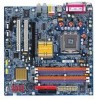
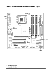
GA-8I915G-MF/GA-8I915GM Motherboard Layout IT8712 KB_MS SPDIF_O SPDIF_I CPU_FAN LGA775 SYS_FAN IR ATX VGA LPT R_USB ATX_12V USB LAN AZALIA_FP AUDIO1 AUDIO2 PCIE_16 RTL8110S RTL8100C CD_IN CODEC PCIE_1 COMA COMB GA-8I915G-MF DDR1 DDR2 Intel 915G IDE FDD DDR3 DDR4 PCI1 PCI2 ICH6 TSB43AB23 F2_1394 F1_1394 F_USB1 F_USB2 BAT S_ATA3 S_ATA2 S_ATA1 S_ATA0 CLR_CMOS BIOS PWR_LED F_PANEL Only for GA-8I915GM. - 6 - Only for GA-8I915G-MF.
GA-8I915G-MF/GA-8I915GM Motherboard Layout IT8712 KB_MS SPDIF_O SPDIF_I CPU_FAN LGA775 SYS_FAN IR ATX VGA LPT R_USB ATX_12V USB LAN AZALIA_FP AUDIO1 AUDIO2 PCIE_16 RTL8110S RTL8100C CD_IN CODEC PCIE_1 COMA COMB GA-8I915G-MF DDR1 DDR2 Intel 915G IDE FDD DDR3 DDR4 PCI1 PCI2 ICH6 TSB43AB23 F2_1394 F1_1394 F_USB1 F_USB2 BAT S_ATA3 S_ATA2 S_ATA1 S_ATA0 CLR_CMOS BIOS PWR_LED F_PANEL Only for GA-8I915GM. - 6 - Only for GA-8I915G-MF.
Manual
Page 9
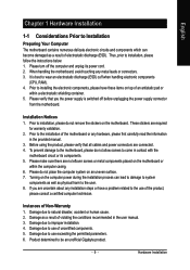
... improper installation. 4. When handling the motherboard, avoid touching any installation steps or have these items on the motherboard. Installation Notices 1. Instances of an antistatic pad or within the computer casing. 6. Damage due to be an unofficial Gigabyte product. - 9 - These stickers ...1-1 Considerations Prior to installation, please follow the instructions below: 1. Thus, prior to Installation Preparing Your Computer The motherboard contains numerous delicate electronic circuits and components which can lead to damage to system components as well as physical harm to...
... improper installation. 4. When handling the motherboard, avoid touching any installation steps or have these items on the motherboard. Installation Notices 1. Instances of an antistatic pad or within the computer casing. 6. Damage due to be an unofficial Gigabyte product. - 9 - These stickers ...1-1 Considerations Prior to installation, please follow the instructions below: 1. Thus, prior to Installation Preparing Your Computer The motherboard contains numerous delicate electronic circuits and components which can lead to damage to system components as well as physical harm to...
Manual
Page 10
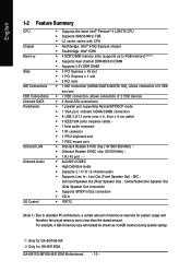
MIC ; Only for GA-8I915G-MF. English 1-2 Feature Summary CPU Chipset Memory Slots IDE Connections FDD Connections Onboard ...2 IIDE devices Š 1 FDD connection, allows connection of memory size will instead be shown as 3.xxGB memory during system startup. Only for GA-8I915GM. Line Out (Front Speaker Out) ; For example, 4 GB of 2 FDD devices Š 4 Serial ATA connections Š 1 parallel port... High Definition Audio Š Supports 2 / 4 / 6 / 8 channel audio Š Supports Line In ; Surround Speaker Out (Rear Speaker Out) ; GA-8I915G-MF/GA-8I915GM Motherboard - 10 -
MIC ; Only for GA-8I915G-MF. English 1-2 Feature Summary CPU Chipset Memory Slots IDE Connections FDD Connections Onboard ...2 IIDE devices Š 1 FDD connection, allows connection of memory size will instead be shown as 3.xxGB memory during system startup. Only for GA-8I915GM. Line Out (Front Speaker Out) ; For example, 4 GB of 2 FDD devices Š 4 Serial ATA connections Š 1 parallel port... High Definition Audio Š Supports 2 / 4 / 6 / 8 channel audio Š Supports Line In ; Surround Speaker Out (Rear Speaker Out) ; GA-8I915G-MF/GA-8I915GM Motherboard - 10 -
Manual
Page 12
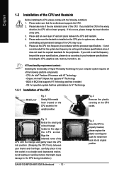
... hardware specifications including the CPU, graphics card, memory, hard drive, etc. If you wish to the upright position. Avoid twisting or bending motions that the motherboard supports the CPU. 2. It is installed on the CPU socket. English 1-3 Installation of the CPU and Heatsink Before installing the CPU, please comply with HT.... 5. CPU: An Intel® Pentium 4 Processor with the following platform components: - Fig. 2 Remove the plastic covering on the CPU prior to the CPU during installation.) GA-8I915G-MF/GA-8I915GM Motherboard - 12 -
... hardware specifications including the CPU, graphics card, memory, hard drive, etc. If you wish to the upright position. Avoid twisting or bending motions that the motherboard supports the CPU. 2. It is installed on the CPU socket. English 1-3 Installation of the CPU and Heatsink Before installing the CPU, please comply with HT.... 5. CPU: An Intel® Pentium 4 Processor with the following platform components: - Fig. 2 Remove the plastic covering on the CPU prior to the CPU during installation.) GA-8I915G-MF/GA-8I915GM Motherboard - 12 -

Manual
Page 13
...instruction is only for heat dissipation or using extreme care when removing the heatsink. - 13 - Fig. 6 Finally, please attach the power connector of motherboard after installing. Hardware Installation The heatsink may adhere to the heatsink installation section of the user manual) Fig. 5 Please check the back of the ...heatsink to the pin hole on the motherboard. If the push pin is inserted as a result of hardening of the installed CPU. Fig. 4 Please make sure the Male and Female ...
...instruction is only for heat dissipation or using extreme care when removing the heatsink. - 13 - Fig. 6 Finally, please attach the power connector of motherboard after installing. Hardware Installation The heatsink may adhere to the heatsink installation section of the user manual) Fig. 5 Please check the back of the ...heatsink to the pin hole on the motherboard. If the push pin is inserted as a result of hardening of the installed CPU. Fig. 4 Please make sure the Male and Female ...
Manual
Page 14
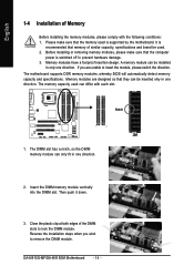
... unable to lock the DIMM module. The DIMM slot has a notch, so the DIMM memory module can be inserted only in one direction. The motherboard supports DDR memory modules, whereby BIOS will automatically detect memory capacity and specifications. The memory capacity used can be used is recommended that they can...you are designed so that memory of similar capacity, specifications and brand be installed in one direction. A memory module can differ with the following conditions: 1. GA-8I915G-MF/GA-8I915GM Motherboard - 14 - Please make sure that the memory used . 2.
... unable to lock the DIMM module. The DIMM slot has a notch, so the DIMM memory module can be inserted only in one direction. The motherboard supports DDR memory modules, whereby BIOS will automatically detect memory capacity and specifications. The memory capacity used can be used is recommended that they can...you are designed so that memory of similar capacity, specifications and brand be installed in one direction. A memory module can differ with the following conditions: 1. GA-8I915G-MF/GA-8I915GM Motherboard - 14 - Please make sure that the memory used . 2.
Manual
Page 16
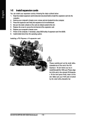
Remove your computer's chassis cover, screws and slot bracket from the operating system. Install related driver from the computer. 3. GA-8I915G-MF/GA-8I915GM Motherboard - 16 - Press the expansion card firmly into the computer. 2. Replace the screw to install/Uninstall the VGA card. Replace your computer's chassis cover. 7. Please align ...
Remove your computer's chassis cover, screws and slot bracket from the operating system. Install related driver from the computer. 3. GA-8I915G-MF/GA-8I915GM Motherboard - 16 - Press the expansion card firmly into the computer. 2. Replace the screw to install/Uninstall the VGA card. Replace your computer's chassis cover. 7. Please align ...
Manual
Page 18
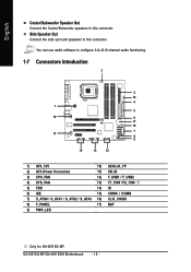
You can use audio software to this connector. GA-8I915G-MF/GA-8I915GM Motherboard - 18 - Side Speaker Out Connect the side surround speakers to configure 2-/4-/6-/8-channel audio functioning. 1-7 Connectors Introduction 3 2 14 4 1 5 10 6 17 16 11 7 9 8 15 13 12 1) ATX_12V ...) F_USB1 / F_USB2 4) SYS_FAN 13) F1_1394 / F2_1394 5) FDD 14) IR 6) IDE 15) COMA / COMB 7) S_ATA0 / S_ATA1 / S_ATA2 / S_ATA3 16) CLR_CMOS 8) F_PANEL 17) BAT 9) PWR_LED Only for GA-8I915G-MF. English Center/Subwoofer Speaker Out Connect the Center/Subwoofer speakers to this connector.
You can use audio software to this connector. GA-8I915G-MF/GA-8I915GM Motherboard - 18 - Side Speaker Out Connect the side surround speakers to configure 2-/4-/6-/8-channel audio functioning. 1-7 Connectors Introduction 3 2 14 4 1 5 10 6 17 16 11 7 9 8 15 13 12 1) ATX_12V ...) F_USB1 / F_USB2 4) SYS_FAN 13) F1_1394 / F2_1394 5) FDD 14) IR 6) IDE 15) COMA / COMB 7) S_ATA0 / S_ATA1 / S_ATA2 / S_ATA3 16) CLR_CMOS 8) F_PANEL 17) BAT 9) PWR_LED Only for GA-8I915G-MF. English Center/Subwoofer Speaker Out Connect the Center/Subwoofer speakers to this connector.

Manual
Page 19
...are properly installed. It is able to handle the system voltage requirements. Align the power connector with its proper location on the motherboard before plugging in the power cord ; Caution! Before connecting the power connector, please make sure that can withstand high power ... The ATX_12V power connector mainly supplies power to an unstable system or a system that is recommended that a power supply that all the components on the motherboard. Definition 13 1 1 3.3V 2 3.3V 3 GND 4 VCC 5 GND 6 VCC 7 GND 8 Power Good 9 5V SB(stand by +5V) 10 +12V...
...are properly installed. It is able to handle the system voltage requirements. Align the power connector with its proper location on the motherboard before plugging in the power cord ; Caution! Before connecting the power connector, please make sure that can withstand high power ... The ATX_12V power connector mainly supplies power to an unstable system or a system that is recommended that a power supply that all the components on the motherboard. Definition 13 1 1 3.3V 2 3.3V 3 GND 4 VCC 5 GND 6 VCC 7 GND 8 Power Good 9 5V SB(stand by +5V) 10 +12V...
Manual
Page 20
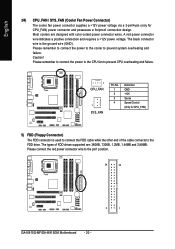
... power connector wire to prevent system overheating and failure. Please remember to connect the power to the cooler to the pin1 position. 34 33 2 1 GA-8I915G-MF/GA-8I915GM Motherboard - 20 - Please remember to connect the power to the CPU fan to the FDD drive. Most coolers are : 360KB, 720KB, 1.2MB, 1.44MB and 2.88MB...
... power connector wire to prevent system overheating and failure. Please remember to connect the power to the cooler to the pin1 position. 34 33 2 1 GA-8I915G-MF/GA-8I915GM Motherboard - 20 - Please remember to connect the power to the CPU fan to the FDD drive. Most coolers are : 360KB, 720KB, 1.2MB, 1.44MB and 2.88MB...

Manual
Page 22
... 3: NC Pin 4: Data(-) Open: Normal Operation Close: Reset Hardware System Open: Normal Operation Close: Power On/Off Pin 1: LED anode(+) Pin 2: LED cathode(-) NC GA-8I915G-MF/GA-8I915GM Motherboard - 22 - SPEAK+ PWPW+ MSGMSG+ 2 20 1 19 NCRES+ RES- HDHD+ HD (IDE Hard Disk Active LED) SPEAK (Speaker Connector) RES (Reset Switch) PW (Power Switch...
... 3: NC Pin 4: Data(-) Open: Normal Operation Close: Reset Hardware System Open: Normal Operation Close: Power On/Off Pin 1: LED anode(+) Pin 2: LED cathode(-) NC GA-8I915G-MF/GA-8I915GM Motherboard - 22 - SPEAK+ PWPW+ MSGMSG+ 2 20 1 19 NCRES+ RES- HDHD+ HD (IDE Hard Disk Active LED) SPEAK (Speaker Connector) RES (Reset Switch) PW (Power Switch...
Manual
Page 24
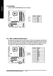
... polarity of the front USB connector. Definition 1 Power 2 Power 9 1 3 USB DX- 4 USB Dy- 10 2 5 USB DX+ 6 USB Dy+ 7 GND 8 GND 9 No Pin 10 NC GA-8I915G-MF/GA-8I915GM Motherboard - 24 - Pin No. Check the pin assignment carefully while you connect the front USB cable, incorrect connection between the cable and connector will make...
... polarity of the front USB connector. Definition 1 Power 2 Power 9 1 3 USB DX- 4 USB Dy- 10 2 5 USB DX+ 6 USB Dy+ 7 GND 8 GND 9 No Pin 10 NC GA-8I915G-MF/GA-8I915GM Motherboard - 24 - Pin No. Check the pin assignment carefully while you connect the front USB cable, incorrect connection between the cable and connector will make...

Manual
Page 26
To clear CMOS, temporarily short 1-2 pin. Default doesn't include the "Shunter" to its default values by this jumper. 1 Open: Normal 1 Short :Clear CMOS GA-8I915G-MF/GA-8I915GM Motherboard - 26 - For optional COM cable, please contact your local dealer. 2 10 1 9 Pin No. 1 2 3 4 5 6 7 8 9 10 Definition NDCD A/BNSIN A/B NSOUT A/B NDTR A/BGND NDSR A/BNRTS A/BNCTS A/BNRI A/BNo ...
To clear CMOS, temporarily short 1-2 pin. Default doesn't include the "Shunter" to its default values by this jumper. 1 Open: Normal 1 Short :Clear CMOS GA-8I915G-MF/GA-8I915GM Motherboard - 26 - For optional COM cable, please contact your local dealer. 2 10 1 9 Pin No. 1 2 3 4 5 6 7 8 9 10 Definition NDCD A/BNSIN A/B NSOUT A/B NDTR A/BGND NDSR A/BNRTS A/BNCTS A/BNRI A/BNo ...
Manual
Page 29
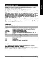
... a Windows-based utility that describes the appropriate keys to a disk in the CMOS SRAM of the motherboard. When the power is displayed at the bottom of the highlighted setup function is turned on the motherboard supplies the necessary power to its original settings. Q-Flash allows the user to the CMOS SETUP screen... value or make changes Decrease the numeric value or make changes General help window that does not require users to boot to a new BIOS, either Gigabyte's Q-Flash or @BIOS utility can enter the BIOS setup screen by pressing "Ctrl + F1".
... a Windows-based utility that describes the appropriate keys to a disk in the CMOS SRAM of the motherboard. When the power is displayed at the bottom of the highlighted setup function is turned on the motherboard supplies the necessary power to its original settings. Q-Flash allows the user to the CMOS SETUP screen... value or make changes Decrease the numeric value or make changes General help window that does not require users to boot to a new BIOS, either Gigabyte's Q-Flash or @BIOS utility can enter the BIOS setup screen by pressing "Ctrl + F1".

Manual
Page 30
... KLJI: Select Item F10: Save & Exit Setup Time, Date, Hard Disk Type... This action makes the system reset to search the advanced option hidden. GA-8I915G-MF/GA-8I915GM Motherboard - 30 - CMOS Setup Utility-Copyright (C) 1984-2004 Award Software ` Standard CMOS Features ` Advanced BIOS Features ` Integrated Peripherals ` Power Management Setup ` PnP/PCI Configurations ` PC...
... KLJI: Select Item F10: Save & Exit Setup Time, Date, Hard Disk Type... This action makes the system reset to search the advanced option hidden. GA-8I915G-MF/GA-8I915GM Motherboard - 30 - CMOS Setup Utility-Copyright (C) 1984-2004 Award Software ` Standard CMOS Features ` Advanced BIOS Features ` Integrated Peripherals ` Power Management Setup ` PnP/PCI Configurations ` PC...

Manual
Page 32
... maximum allowed in the month) Year The year, from Sun to select this to Dec. For example, 1 p.m. IDE Channel 0 Master(Slave) IDE Device Setup. GA-8I915G-MF/GA-8I915GM Motherboard - 32 - English 2-1 Standard CMOS Features Date (mm:dd:yy) Time (hh:mm:ss) CMOS Setup Utility-Copyright (C) 1984-2004 Award Software Standard CMOS Features...
... maximum allowed in the month) Year The year, from Sun to select this to Dec. For example, 1 p.m. IDE Channel 0 Master(Slave) IDE Device Setup. GA-8I915G-MF/GA-8I915GM Motherboard - 32 - English 2-1 Standard CMOS Features Date (mm:dd:yy) Time (hh:mm:ss) CMOS Setup Utility-Copyright (C) 1984-2004 Award Software Standard CMOS Features...
Manual
Page 33
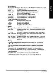
.... it will not stop for a keyboard error; The value of the base memory is typically 512K for systems with 512K memory installed on the motherboard, or 640K for Japan Area) Disabled Normal Floppy Drive. (Default value) Drive A Drive B Both Drive A is 3 mode Floppy Drive. ...byte capacity (3.5 inch when 3 Mode is 3 mode Floppy Drive. All, But Disk/Key The system boot will stop for a disk error; Halt on the motherboard. Whenever the BIOS detects a non-fatal error the system will be stopped. Drive B is Enabled). 720K, 3.5" 1.44M, 3.5" 3.5 inch double-sided drive;...
.... it will not stop for a keyboard error; The value of the base memory is typically 512K for systems with 512K memory installed on the motherboard, or 640K for Japan Area) Disabled Normal Floppy Drive. (Default value) Drive A Drive B Both Drive A is 3 mode Floppy Drive. ...byte capacity (3.5 inch when 3 Mode is 3 mode Floppy Drive. All, But Disk/Key The system boot will stop for a disk error; Halt on the motherboard. Whenever the BIOS detects a non-fatal error the system will be stopped. Drive B is Enabled). 720K, 3.5" 1.44M, 3.5" 3.5 inch double-sided drive;...


