
User Manual
Page 2
... Summary 5 GA-8ICXT Motherboard Layout 7 Chapter 2Hardware Installation Process 9 Step 1: Installing Processor and CPU Haet Sink 10 Step1-1: Installing CPU 10 Step1-2: Installing Heat Sink 11 Step 2: Install memory modules 12 Step 3: Install expansion cards 14 Step 4: Connect ribbon cables, cabinet wires, and power supply 15 Step 4-1 : I/O Back Panel Introduction 15 Step 4-2 :Connectors & Jumper Setting Introduction 17 Chapter 3 BIOS Setup 27 Main ...29 Advanced 32 Memory Configuration ...33 PCI Configuration ...35 I/O Device Configuration 37 Advanced Chipset Control 41 Security...
... Summary 5 GA-8ICXT Motherboard Layout 7 Chapter 2Hardware Installation Process 9 Step 1: Installing Processor and CPU Haet Sink 10 Step1-1: Installing CPU 10 Step1-2: Installing Heat Sink 11 Step 2: Install memory modules 12 Step 3: Install expansion cards 14 Step 4: Connect ribbon cables, cabinet wires, and power supply 15 Step 4-1 : I/O Back Panel Introduction 15 Step 4-2 :Connectors & Jumper Setting Introduction 17 Chapter 3 BIOS Setup 27 Main ...29 Advanced 32 Memory Configuration ...33 PCI Configuration ...35 I/O Device Configuration 37 Advanced Chipset Control 41 Security...
User Manual
Page 3
English Table of Content Chapter 4 Technical Reference 55 Block Diagram 55 Chapter 5 Driver Installation 56 A.Intel Chipset Software Installation Utilities 56 B.Intel Network Driver Installation 58 C.Intel VGA Driver Installation 59 D.Adapetc RAID Driver Installation 60 E.DirectX 9.0 Driver Installation 61 Chapter 6 Appendix 62 Acronyms ...62 3
English Table of Content Chapter 4 Technical Reference 55 Block Diagram 55 Chapter 5 Driver Installation 56 A.Intel Chipset Software Installation Utilities 56 B.Intel Network Driver Installation 58 C.Intel VGA Driver Installation 59 D.Adapetc RAID Driver Installation 60 E.DirectX 9.0 Driver Installation 61 Chapter 6 Appendix 62 Acronyms ...62 3
User Manual
Page 4
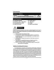
.... Ensure that the ATX power supply is switched off , so be a little hard to the chassis... Unplug your hands). Date Dec. 2004 Item Checklist The GA-8ICXT motherboard IDE (ATA100 ) cable x 1 / Floppy cable x 1 CD for motherboard driver & utility GA-8ICXT user's manual Serial ATA cable x 4 COM2 cable x 1 I/O Shield GA-8ICXT Quick Install Label WARNING! Computer motherboards and expansion cards contain very delicate Integrated Circuit (IC) chips. Installing the motherboard to cut the bottom portion of your hands to a safely grounded object or...
.... Ensure that the ATX power supply is switched off , so be a little hard to the chassis... Unplug your hands). Date Dec. 2004 Item Checklist The GA-8ICXT motherboard IDE (ATA100 ) cable x 1 / Floppy cable x 1 CD for motherboard driver & utility GA-8ICXT user's manual Serial ATA cable x 4 COM2 cable x 1 I/O Shield GA-8ICXT Quick Install Label WARNING! Computer motherboards and expansion cards contain very delicate Integrated Circuit (IC) chips. Installing the motherboard to cut the bottom portion of your hands to a safely grounded object or...
User Manual
Page 5
...Summary Form Factor CPU Chipset Memory I /O y Supports 3 PCI slots 32-Bit/33MHz (5V) y Supports 2 PCI-X slots 64/100MHz (3.3V) y Supports 1 PCI-Express X4 slot y ICH6R y Supports SATA RAID 0,1 y 1 Floppy port supports 2 FDD with 360K, 720K,1.2M, 1.44M and 2.88M bytes. y Supports Intel® Pentium Prescot LGA 775 processor y Intel® Prescot LGA 775 supports 800MHz FSB y L2 cache on 8Mb flash RAM - 5 - y 1 Parallel port supports Normal/EPP/ECP mode y 1 Serial port (COM) y 2 x USB 2.0 y 1 VGA Connector y 2 x LAN RJ45 y CPU/Power/System Fan Revolution Detect y CPU shutdown when overheat...
...Summary Form Factor CPU Chipset Memory I /O y Supports 3 PCI slots 32-Bit/33MHz (5V) y Supports 2 PCI-X slots 64/100MHz (3.3V) y Supports 1 PCI-Express X4 slot y ICH6R y Supports SATA RAID 0,1 y 1 Floppy port supports 2 FDD with 360K, 720K,1.2M, 1.44M and 2.88M bytes. y Supports Intel® Pentium Prescot LGA 775 processor y Intel® Prescot LGA 775 supports 800MHz FSB y L2 cache on 8Mb flash RAM - 5 - y 1 Parallel port supports Normal/EPP/ECP mode y 1 Serial port (COM) y 2 x USB 2.0 y 1 VGA Connector y 2 x LAN RJ45 y CPU/Power/System Fan Revolution Detect y CPU shutdown when overheat...
User Manual
Page 9
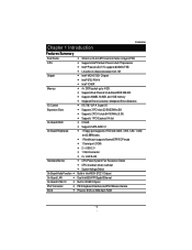
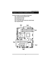
Connect ribbon cables, cabinet wires, and power supply Step 5- Setup BIOS software Step1 Step 4 BC117 C418 ATX_12V1 I3 DDR3 DDR4 COM1 USB1 KB_MS1 Step 2 DDR2 DDR1 FS4 FAN2 LPT1 2 1 VGA1 SW1...COM2 HDD_LED2 USB2 Step4 9 BAT1 IPMB2 JP1 F_PANEL3 CLR_CMOS1 FFC1 IPMB1 JIDES1 IDE1 I4 FDC1 S_ATA1 S_ATA2 S_ATA3 Step 4 Install memory modules Step 3- Hardware Installation Process Chapter 2 Hardware Installation Process To set up your computer, you must complete the following steps: Step 1- Install expansion cards Step 4- Install the Central Processing Unit (CPU) Step 2-
Connect ribbon cables, cabinet wires, and power supply Step 5- Setup BIOS software Step1 Step 4 BC117 C418 ATX_12V1 I3 DDR3 DDR4 COM1 USB1 KB_MS1 Step 2 DDR2 DDR1 FS4 FAN2 LPT1 2 1 VGA1 SW1...COM2 HDD_LED2 USB2 Step4 9 BAT1 IPMB2 JP1 F_PANEL3 CLR_CMOS1 FFC1 IPMB1 JIDES1 IDE1 I4 FDC1 S_ATA1 S_ATA2 S_ATA3 Step 4 Install memory modules Step 3- Hardware Installation Process Chapter 2 Hardware Installation Process To set up your computer, you must complete the following steps: Step 1- Install expansion cards Step 4- Install the Central Processing Unit (CPU) Step 2-
User Manual
Page 10
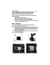
... following cautions: 1. Step 2 Remove the plastic covering on the processor before placing cooling fan. 4. Step 5 Close the lever, reverse step 1 & 2. 10 English GA-8ICXT Motherboard Step 1: Installing Processor and CPU Haet Sink Before installing the processor and cooling fan, adhere to the CPU during installation.) Step 4 Once the CPU is supported by the motherboard. 5. Step1-1: Installing CPU Step 1 Gently lift the metal lever located on the CPU socket to the upper-right...
... following cautions: 1. Step 2 Remove the plastic covering on the processor before placing cooling fan. 4. Step 5 Close the lever, reverse step 1 & 2. 10 English GA-8ICXT Motherboard Step 1: Installing Processor and CPU Haet Sink Before installing the processor and cooling fan, adhere to the CPU during installation.) Step 4 Once the CPU is supported by the motherboard. 5. Step1-1: Installing CPU Step 1 Gently lift the metal lever located on the CPU socket to the upper-right...
User Manual
Page 12
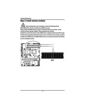
... BC117 C418 ATX_12V1 I3 DDR3 DDR4 COM1 USB1 KB_MS1 DDR2 DDR1 FS4 FAN2 LPT1 2 1 VGA1 GA-8ICXT Motherboard Step 2: Install memory modules Before installing the processor and heatsink, adhere to the notch. Please change the insert orientation. GA-8ICXT has 4 dual inline memory module (DIMM) socets. It supports the Dual Channel Technology. Memory size can only fit in one notches. Please note that the DIMM module can vary between...
... BC117 C418 ATX_12V1 I3 DDR3 DDR4 COM1 USB1 KB_MS1 DDR2 DDR1 FS4 FAN2 LPT1 2 1 VGA1 GA-8ICXT Motherboard Step 2: Install memory modules Before installing the processor and heatsink, adhere to the notch. Please change the insert orientation. GA-8ICXT has 4 dual inline memory module (DIMM) socets. It supports the Dual Channel Technology. Memory size can only fit in one notches. Please note that the DIMM module can vary between...
User Manual
Page 18
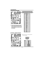
...WOR1 WOL1 B ) ATX 12V( +12V Power Connector) IPMB2 JP1 F_PANEL3 CLR_CMOS1 PXH_HEATSINK FFC1 IPMB1 JIDES1 IDE1 I4 FDC1 S_ATA1 S_ATA2 F_PANEL1 FS4 FAN2 S_ATA3 DDR1 PIN No. 1 2...used only for CPU1 Core Voltage. English GA-8ICXT Motherboard A) ATX (ATX Power Connector) BC117 C418 ATX_12V1 1 12 13 24 I3 DDR3 DDR4 COM1 USB1 KB_MS1 DDR2 I1 FAN7 LED3 R571 SW1 VGA1 LPT1 2 1 CI2 WOL1 WOR1 HDD_LED1 PCI_X2 EC45 PCI_E FAN5 COM2 HDD_LED2 USB2 BAT1 C187 CI1 AC power cord should only be connected to your power supply unit after ATX power cable and other related devices...
...WOR1 WOL1 B ) ATX 12V( +12V Power Connector) IPMB2 JP1 F_PANEL3 CLR_CMOS1 PXH_HEATSINK FFC1 IPMB1 JIDES1 IDE1 I4 FDC1 S_ATA1 S_ATA2 F_PANEL1 FS4 FAN2 S_ATA3 DDR1 PIN No. 1 2...used only for CPU1 Core Voltage. English GA-8ICXT Motherboard A) ATX (ATX Power Connector) BC117 C418 ATX_12V1 1 12 13 24 I3 DDR3 DDR4 COM1 USB1 KB_MS1 DDR2 I1 FAN7 LED3 R571 SW1 VGA1 LPT1 2 1 CI2 WOL1 WOR1 HDD_LED1 PCI_X2 EC45 PCI_E FAN5 COM2 HDD_LED2 USB2 BAT1 C187 CI1 AC power cord should only be connected to your power supply unit after ATX power cable and other related devices...
User Manual
Page 28
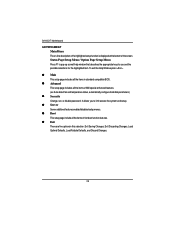
GA-8ICXT Motherboard GETTINGHELP Main Menu The on-line description of the highlighted setup function is displayed at the bottom of AMI special enhanced features. (ex: Auto detect fan and temperature status, automatically configure hard disk parameters.) z Security Change, set, or disable password. Status Page Setup Menu / Option Page Setup Menu Press F1 to pop up a small help window that describes the appropriate keys to limit access the system and setup. z Advanced This setup page includes all the...
GA-8ICXT Motherboard GETTINGHELP Main Menu The on-line description of the highlighted setup function is displayed at the bottom of AMI special enhanced features. (ex: Auto detect fan and temperature status, automatically configure hard disk parameters.) z Security Change, set, or disable password. Status Page Setup Menu / Option Page Setup Menu Press F1 to pop up a small help window that describes the appropriate keys to limit access the system and setup. z Advanced This setup page includes all the...
User Manual
Page 30
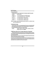
... the hard disk initialized after powering up, prior to F that has been installed in the documentation form your drive must match with the drive table. There are two types: auto type, and manual type. The hard disk will not work properly if you select User Type, related information will automatically detect HDD type. IDE Primary Master, Slave / Secondary Master, Slave, Parallel ATA The category identifies the types of a hard disk by BIOS. GA-8ICXT Motherboard Legacy Diskette...
... the hard disk initialized after powering up, prior to F that has been installed in the documentation form your drive must match with the drive table. There are two types: auto type, and manual type. The hard disk will not work properly if you select User Type, related information will automatically detect HDD type. IDE Primary Master, Slave / Secondary Master, Slave, Parallel ATA The category identifies the types of a hard disk by BIOS. GA-8ICXT Motherboard Legacy Diskette...
User Manual
Page 31
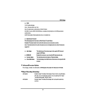
... technology. (Default value) Disables Hyper-Threading Technology when using other operating systems. 31 Disabled: The data transfer from and to max imize the IDE data transfer rate. This field shows the information of Multi-Sector Transfer Mode. Users: Set parameters by User. Multi-Sector Transfer This field displays the information of Teansfer Mode. This filed displays the DMA mode of CPU Speed, Processor ID, Processor L2 Cache. BIOS Setup TYPE 1-39: Predefined types. LBA Mode 32-Bit...
... technology. (Default value) Disables Hyper-Threading Technology when using other operating systems. 31 Disabled: The data transfer from and to max imize the IDE data transfer rate. This field shows the information of Multi-Sector Transfer Mode. Users: Set parameters by User. Multi-Sector Transfer This field displays the information of Teansfer Mode. This filed displays the DMA mode of CPU Speed, Processor ID, Processor L2 Cache. BIOS Setup TYPE 1-39: Predefined types. LBA Mode 32-Bit...
User Manual
Page 35
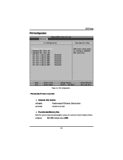
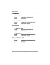
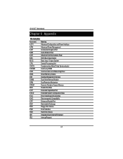
PCI Configuration BIOS Setup Figure 2-2: PCI Configuration Embedded Video Controller Onboard VGA Control Enabled Enable onboard VGA device. (Default value) Disabled Disable this function. Default value is 8MB. 35 Pre-Allocated Memory Size Select the amount of pre-allocated graphics memory for use by the Internal Graphics Device. Options 1MB, 8MB.
PCI Configuration BIOS Setup Figure 2-2: PCI Configuration Embedded Video Controller Onboard VGA Control Enabled Enable onboard VGA device. (Default value) Disabled Disable this function. Default value is 8MB. 35 Pre-Allocated Memory Size Select the amount of pre-allocated graphics memory for use by the Internal Graphics Device. Options 1MB, 8MB.
User Manual
Page 36
...) EmbeddedNIC #2 Onboard LAN2/ Control Enabled Enable onboard LAN2 device. (Default value) Disabled Disable this item to initialize device expansion ROM. Option ROM Scan Enabled Enableing this function. 36 Disabled Disable this function. (Defualt value) PCI Slot 1/2/3/4/5 Option ROM Enabled Disabled Enableing this item to initialize device expansion ROM. (Defualt value) Disable this item to initialize device expansion ROM. GA-8ICXT Motherboard EmbeddedNIC #1 Onboard LAN1/ Control Enabled Enable onboard LAN1 device. (Default value) Disabled Disable this function...
...) EmbeddedNIC #2 Onboard LAN2/ Control Enabled Enable onboard LAN2 device. (Default value) Disabled Disable this item to initialize device expansion ROM. Option ROM Scan Enabled Enableing this function. 36 Disabled Disable this function. (Defualt value) PCI Slot 1/2/3/4/5 Option ROM Enabled Disabled Enableing this item to initialize device expansion ROM. (Defualt value) Disable this item to initialize device expansion ROM. GA-8ICXT Motherboard EmbeddedNIC #1 Onboard LAN1/ Control Enabled Enable onboard LAN1 device. (Default value) Disabled Disable this function...
User Manual
Page 38
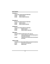
... to the desired value. type mouse. USB Controller This item allows users to enable or disable the USB device by using this option. Disabled Disable the configuration. Disabled Disable the configuration. GA-8ICXT Motherboard Serial Port A This allows users to configure serial prot A by using this option. Disabled Disable the configuration. Enabled Enable the configuration. (Default value) PS/2 Mouse Set this option 'Enabled' to be enabled regardless if a mouse is present. (Default value) Disabled 'Disabled' prevents any installed PS/2 mouse from functioning...
... to the desired value. type mouse. USB Controller This item allows users to enable or disable the USB device by using this option. Disabled Disable the configuration. Disabled Disable the configuration. GA-8ICXT Motherboard Serial Port A This allows users to configure serial prot A by using this option. Disabled Disable the configuration. Enabled Enable the configuration. (Default value) PS/2 Mouse Set this option 'Enabled' to be enabled regardless if a mouse is present. (Default value) Disabled 'Disabled' prevents any installed PS/2 mouse from functioning...
User Manual
Page 39
...Enables support for legacy USB (Default Value) Disabled Disables support for legacy USB Serial ATA Enabled Disabled Enables on-board serial ATA function. (Default Value) Disables on-board serial ATA function. ` Native Mode Operation This option allows user to function support for Serial ATA function. BIOS Setup USB 2.0 Controller This item allows users to enable or disable the USB 2.0 device by setting item to Serial ATA. ` SATA Controller Mode Option Compatible Mode SATA and PATA drives are auto-detected and placed in Legacy mode. (Default value) Enhanced (non-AHCI) Mode SATA...
...Enables support for legacy USB (Default Value) Disabled Disables support for legacy USB Serial ATA Enabled Disabled Enables on-board serial ATA function. (Default Value) Disables on-board serial ATA function. ` Native Mode Operation This option allows user to function support for Serial ATA function. BIOS Setup USB 2.0 Controller This item allows users to enable or disable the USB 2.0 device by setting item to Serial ATA. ` SATA Controller Mode Option Compatible Mode SATA and PATA drives are auto-detected and placed in Legacy mode. (Default value) Enhanced (non-AHCI) Mode SATA...
User Manual
Page 58
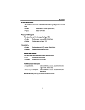
... contains LAN driver for Windows 64 Bit operating system, RK2_Gold folder contains other available operating systems. 3. Intel Network Driver Installation Insert the driver CD-title that came with your motherboard into your CD-ROM driver, the driver CD-title will auto start the installation. 2. Installation Procedures: 1. Auto Run windows Intel Network Drivers 1.Click "Intel Network Driver" item. (1) 2. GA-8ICXT Motherboard B. If not, please double click the CD-ROM device icon in "My computer", and execute the setup.exe...
... contains LAN driver for Windows 64 Bit operating system, RK2_Gold folder contains other available operating systems. 3. Intel Network Driver Installation Insert the driver CD-title that came with your motherboard into your CD-ROM driver, the driver CD-title will auto start the installation. 2. Installation Procedures: 1. Auto Run windows Intel Network Drivers 1.Click "Intel Network Driver" item. (1) 2. GA-8ICXT Motherboard B. If not, please double click the CD-ROM device icon in "My computer", and execute the setup.exe...
User Manual
Page 59
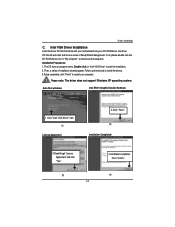
...-ROM device icon in "My computer", and execute the setup.exe. Please note: The driver does not support Windows XP opearting system. Auto Run windows Intel E7221 Graphic Installer Software 1. Then, a series of Setup Wizard dialog boxes. Driver Installation C. Click "Intel VGA Driver" item. (1) License Aggrement 2.Click "Next". (2) Installation Completed 3.Read throgh 'License Agreement' and click "Yes". (3) 59 4. Follow up the wizards to install the drivers. 3.Setup completed, click "Finish" to start...
...-ROM device icon in "My computer", and execute the setup.exe. Please note: The driver does not support Windows XP opearting system. Auto Run windows Intel E7221 Graphic Installer Software 1. Then, a series of Setup Wizard dialog boxes. Driver Installation C. Click "Intel VGA Driver" item. (1) License Aggrement 2.Click "Next". (2) Installation Completed 3.Read throgh 'License Agreement' and click "Yes". (3) 59 4. Follow up the wizards to install the drivers. 3.Setup completed, click "Finish" to start...
User Manual
Page 60
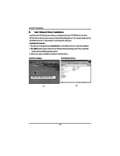
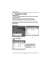
... the RAID driver. (3) 60 Adapetc RAID Driver Installation Installation Procedures: 1. Click "Adaptec RAID Driver" item. (1) (2) RAID Driver Operating System Selection Refer to yor operating systsem, select the desired folder to install the RAID driver. 4. The CD auto run program starts, Double click on "Adapyec RAID Driver" to a floppy diskette. When installing, insert the dsikette into floppy drive. Double click "Driver" folder. 3. Auto Run windows 1. GA-8ICXT Motherboard D. Note: User must enable "SATA RAID" function in the BIOS setup meun before installing Adaptec RAID...
... the RAID driver. (3) 60 Adapetc RAID Driver Installation Installation Procedures: 1. Click "Adaptec RAID Driver" item. (1) (2) RAID Driver Operating System Selection Refer to yor operating systsem, select the desired folder to install the RAID driver. 4. The CD auto run program starts, Double click on "Adapyec RAID Driver" to a floppy diskette. When installing, insert the dsikette into floppy drive. Double click "Driver" folder. 3. Auto Run windows 1. GA-8ICXT Motherboard D. Note: User must enable "SATA RAID" function in the BIOS setup meun before installing Adaptec RAID...
User Manual
Page 61
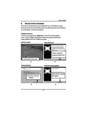
... the installation guide. Driver Installation E. Follow up the wizards to install the drivers. 3.Setup completed, click "Finish" to start the installation. 2. Installation Procedures: 1. Auto Run windows License Agreement 1.Click "DirectX 9.0 Driver" item (1) Starting Installaiton 2.Select "I accept the agreement and click "Next". (2) Installaiton Wizard completed 3. DirectX 9.0 Driver Installation Insert the driver CD-title that came with your motherboard into your computer. If not, please double click the CD-ROM device icon...
... the installation guide. Driver Installation E. Follow up the wizards to install the drivers. 3.Setup completed, click "Finish" to start the installation. 2. Installation Procedures: 1. Auto Run windows License Agreement 1.Click "DirectX 9.0 Driver" item (1) Starting Installaiton 2.Select "I accept the agreement and click "Next". (2) Installaiton Wizard completed 3. DirectX 9.0 Driver Installation Insert the driver CD-title that came with your motherboard into your computer. If not, please double click the CD-ROM device icon...
User Manual
Page 62
GA-8ICXT Motherboard RCehvaispitoenr H6istAoprypendix Acronyms Acronyms Meaning ACPI Advanced Configuration and Power Interface APM Advanced Power Management AGP Accelerated Graphics Port AMR Audio Modem Riser ACR Advanced Communications Riser BBS BIOS Boot Specification BIOS Basic Input / Output System CPU Central Processing Unit CMOS Complementary Metal Oxide Semiconductor CRIMM Continuity RIMM CNR Communication and Networking Riser DMA Direct Memory Access DMI Desktop Management Interface DIMM Dual Inline Memory Module DRM Dual Retention Mechanism DRAM ...
GA-8ICXT Motherboard RCehvaispitoenr H6istAoprypendix Acronyms Acronyms Meaning ACPI Advanced Configuration and Power Interface APM Advanced Power Management AGP Accelerated Graphics Port AMR Audio Modem Riser ACR Advanced Communications Riser BBS BIOS Boot Specification BIOS Basic Input / Output System CPU Central Processing Unit CMOS Complementary Metal Oxide Semiconductor CRIMM Continuity RIMM CNR Communication and Networking Riser DMA Direct Memory Access DMI Desktop Management Interface DIMM Dual Inline Memory Module DRM Dual Retention Mechanism DRAM ...


