
User Manual
Page 6
... 5 GA-8LD533 Series Motherboard Layout 7 Chapter 2 Hardware Installation Process 8 Step 1: Install the Central Processing Unit (CPU 9 Step1-1 CPU Installation 9 Step1-2 CPU Heat Sink Installation 10 Step 2: Install memory modules 11 Step 3: Install expansion cards 12 Step 4: Connect ribbon cables, cabinet wires, and power supply 13 Step4-1 I/O Back Panel Introduction 13 Step4-2 Connectors Introduction 15 Chapter 3 BIOS Setup 21 The Main Menu (For example: BIOS Ver. :F1 22 Standard CMOS Features 24 Advanced BIOS Features 27 Integrated Peripherals 29 GA-8LD533 Series Motherboard...
... 5 GA-8LD533 Series Motherboard Layout 7 Chapter 2 Hardware Installation Process 8 Step 1: Install the Central Processing Unit (CPU 9 Step1-1 CPU Installation 9 Step1-2 CPU Heat Sink Installation 10 Step 2: Install memory modules 11 Step 3: Install expansion cards 12 Step 4: Connect ribbon cables, cabinet wires, and power supply 13 Step4-1 I/O Back Panel Introduction 13 Step4-2 Connectors Introduction 15 Chapter 3 BIOS Setup 21 The Main Menu (For example: BIOS Ver. :F1 22 Standard CMOS Features 24 Advanced BIOS Features 27 Integrated Peripherals 29 GA-8LD533 Series Motherboard...
User Manual
Page 8
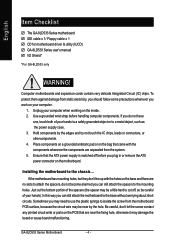
... hands to a safely grounded object or to the chassis... Installing the motherboard to a metal object, such as the power supply case. 3. English Item Checklist The GA-8LD533 Series motherboard IDE cable x 1/ Floppy cable x 1 CD for motherboard driver & utility (IUCD) GA-8LD533 Series user's manual I/O Shield* *For GA-8LD533 only WARNING! Be careful, don't let the screw contact any printed circuit write or parts on the motherboard. Computer motherboards and expansion cards contain very delicate Integrated Circuit (IC) chips. To protect...
... hands to a safely grounded object or to the chassis... Installing the motherboard to a metal object, such as the power supply case. 3. English Item Checklist The GA-8LD533 Series motherboard IDE cable x 1/ Floppy cable x 1 CD for motherboard driver & utility (IUCD) GA-8LD533 Series user's manual I/O Shield* *For GA-8LD533 only WARNING! Be careful, don't let the screw contact any printed circuit write or parts on the motherboard. Computer motherboards and expansion cards contain very delicate Integrated Circuit (IC) chips. To protect...
User Manual
Page 9
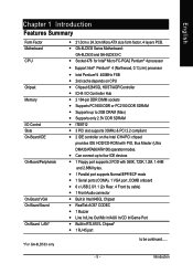
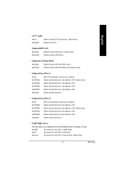
... onboard y 6 x USB 2.0/1.1 (2x Rear, 4 Front by cable) y 1 Front Audio connector y Built in Intel 845GL Chipset y RealTek AC97 CODEC y 1 Buzzer y Line In/Line Out/Mic In/AUX In/CD In/Game Port y Builit in RTL8101L Chipset* y 1 RJ 45 port *For GA-8LD533 only to 2GB DRAM (Max) y Supports only 2.5V DDR SDRAM y ITE8712 y 3 PCI slot supports 33MHz & PCI 2.2 compliant y 2 IDE controller on CPU y Chipset 82845GL HOST/AGP/Controller y ICH4 I /O Control Slots On-Board IDE On-Board Peripherals On-Board VGA On-Board Sound...
... onboard y 6 x USB 2.0/1.1 (2x Rear, 4 Front by cable) y 1 Front Audio connector y Built in Intel 845GL Chipset y RealTek AC97 CODEC y 1 Buzzer y Line In/Line Out/Mic In/AUX In/CD In/Game Port y Builit in RTL8101L Chipset* y 1 RJ 45 port *For GA-8LD533 only to 2GB DRAM (Max) y Supports only 2.5V DDR SDRAM y ITE8712 y 3 PCI slot supports 33MHz & PCI 2.2 compliant y 2 IDE controller on CPU y Chipset 82845GL HOST/AGP/Controller y ICH4 I /O Control Slots On-Board IDE On-Board Peripherals On-Board VGA On-Board Sound...
User Manual
Page 10
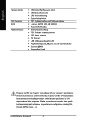
... system bus frequency over the CPU's specification because these specific bus frequencies properly will depend on y AC Recovery y USB KB/Mouse wake up from S3 y Poly fuse for CPU, chipset and most of the peripherals. English Hardware Monitor PS/2 Connector BIOS Additional Features y CPU/System Fan Revolution detect y CPU/System Fan Control y CPU Overheat Warning y System Voltage Detect y PS/2 Keyboard interface and PS/2 Mouse interace y Licensed AWARD BIOS, 2M bit FWH y Support Q-flash function y External Modem wake up y PS/2 Keyboard password power...
... system bus frequency over the CPU's specification because these specific bus frequencies properly will depend on y AC Recovery y USB KB/Mouse wake up from S3 y Poly fuse for CPU, chipset and most of the peripherals. English Hardware Monitor PS/2 Connector BIOS Additional Features y CPU/System Fan Revolution detect y CPU/System Fan Control y CPU Overheat Warning y System Voltage Detect y PS/2 Keyboard interface and PS/2 Mouse interace y Licensed AWARD BIOS, 2M bit FWH y Support Q-flash function y External Modem wake up y PS/2 Keyboard password power...
User Manual
Page 12
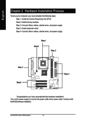
Install memory modules Step 3- Continue with the BIOS/software installation. Install the Central Processing Unit (CPU) Step 2- Turn on the power supply or connect the power cable to the power outlet. Install expansion cards Step 4- GA-8LD533 Series Motherboard - 8 - English Chapter 2 Hardware Installation Process To set up your computer, you have accomplished the hardware installation! Connect ribbon cables, cabinet wires, and power supply Step1 Step4 Step 2 Step 4 Step3 Step 4 Congratulations you must complete the following steps: Step 1- Connect ribbon cables, cabinet...
Install memory modules Step 3- Continue with the BIOS/software installation. Install the Central Processing Unit (CPU) Step 2- Turn on the power supply or connect the power cable to the power outlet. Install expansion cards Step 4- GA-8LD533 Series Motherboard - 8 - English Chapter 2 Hardware Installation Process To set up your computer, you have accomplished the hardware installation! Connect ribbon cables, cabinet wires, and power supply Step1 Step4 Step 2 Step 4 Step3 Step 4 Congratulations you must complete the following steps: Step 1- Connect ribbon cables, cabinet...

User Manual
Page 16
... bandwidth of expansion card from the operating system GA-8LD533 Series Motherboard - 12 - Step 3: Install expansion cards 1. Replace the screw to conventional SDRAM's 3.3 volts, DDR memory is a compelling solution for small form factor desktops and notebook applications. Install related driver from BIOS. 8. Replace your computer's chassis cover, screws and slot bracket from existing SDRAM designs due to build high performance and low latency DRAM subsystems that builds on...
... bandwidth of expansion card from the operating system GA-8LD533 Series Motherboard - 12 - Step 3: Install expansion cards 1. Replace the screw to conventional SDRAM's 3.3 volts, DDR memory is a compelling solution for small form factor desktops and notebook applications. Install related driver from BIOS. 8. Replace your computer's chassis cover, screws and slot bracket from existing SDRAM designs due to build high performance and low latency DRAM subsystems that builds on...
User Manual
Page 18
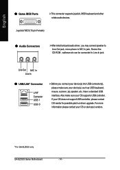
... GA-8LD533 Series Motherboard - 14 - For more information please contact your OS does not support USB controller, please contact OS vendor for possible patch or driver upgrade. Have a standard USB interface. Also make sure your OS supports USB controller. Joystick/ MIDI (15 pin Female) [ Audio Connectors After install onboard audio driver, you connect your device(s) into USB connector(s), please make sure your device(s) such as USB keyboard, mouse, scanner, zip,speaker..etc. Line Out MIC In Line In \ USB/LAN* Connector LAN* Connector USB 1 USB...
... GA-8LD533 Series Motherboard - 14 - For more information please contact your OS does not support USB controller, please contact OS vendor for possible patch or driver upgrade. Have a standard USB interface. Also make sure your OS supports USB controller. Joystick/ MIDI (15 pin Female) [ Audio Connectors After install onboard audio driver, you connect your device(s) into USB connector(s), please make sure your device(s) such as USB keyboard, mouse, scanner, zip,speaker..etc. Line Out MIC In Line In \ USB/LAN* Connector LAN* Connector USB 1 USB...
User Manual
Page 22
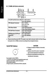
... + type recommended by the manufacturer. Pin 3: NC Pin 4: Data(-) RES (Reset Switch) Open: Normal Operation Close: Reset Hardware System PW (Soft Power Connector) Open: Normal Operation Close: Power On/Off MPD(Message LED/Power/ Pin 1: LED anode(+) Sleep LED) Pin 2: LED cathode(-) NC NC Please connect the power LED, PC speaker, reset switch and power switch etc of your chassis front panel to the F_PANEL connector according to the pin assignment above. 10) BATTERY (Battery) CAUTION Danger of used batteries according to erase CMOS... 1.Turn...
... + type recommended by the manufacturer. Pin 3: NC Pin 4: Data(-) RES (Reset Switch) Open: Normal Operation Close: Reset Hardware System PW (Soft Power Connector) Open: Normal Operation Close: Power On/Off MPD(Message LED/Power/ Pin 1: LED anode(+) Sleep LED) Pin 2: LED cathode(-) NC NC Please connect the power LED, PC speaker, reset switch and power switch etc of your chassis front panel to the F_PANEL connector according to the pin assignment above. 10) BATTERY (Battery) CAUTION Danger of used batteries according to erase CMOS... 1.Turn...
User Manual
Page 24
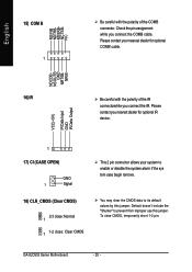
To clear CMOS, temporarily short 1-2 pin. GA-8LD533 Series Motherboard - 20 - Please contact your system to enable or disable the system alarm if the sys tem case begin remove. Check the pin assignment while you nearest dealer for optional IR device. 1 17) CI (CASE OPEN) GND 1 Signal 18) CLR_CMOS (Clear CMOS) 1 2-3 close: Normal 1 1-2 close: Clear CMOS This 2 pin connector allows your nearest dealer for optional COMB cable. NRIB- Please contact you connect the COMB cable. Default doesn't include...
To clear CMOS, temporarily short 1-2 pin. GA-8LD533 Series Motherboard - 20 - Please contact your system to enable or disable the system alarm if the sys tem case begin remove. Check the pin assignment while you nearest dealer for optional IR device. 1 17) CI (CASE OPEN) GND 1 Signal 18) CLR_CMOS (Clear CMOS) 1 2-3 close: Normal 1 1-2 close: Clear CMOS This 2 pin connector allows your nearest dealer for optional COMB cable. NRIB- Please contact you connect the COMB cable. Default doesn't include...
User Manual
Page 26
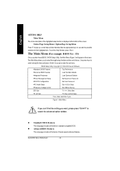
... Status Set User Passw ord Sav e & Ex it Setup }Frequency /Voltage Control ESC:Quit Ex it Without Sav ing higf:Select Item F8: Q-Flash F10:Sav e & Ex it Setup Time, Date, Hard Disk Ty pe... l Standard CMOS Features This setup page includes all the items of the screen. GA-8LD533 Series Motherboard - 22 - To exit the Help Window press . The Main Menu (For example: BIOS Ver. : F1) Once you enter Award BIOS CMOS Setup Utility, the Main Menu (Figure...
... Status Set User Passw ord Sav e & Ex it Setup }Frequency /Voltage Control ESC:Quit Ex it Without Sav ing higf:Select Item F8: Q-Flash F10:Sav e & Ex it Setup Time, Date, Hard Disk Ty pe... l Standard CMOS Features This setup page includes all the items of the screen. GA-8LD533 Series Motherboard - 22 - To exit the Help Window press . The Main Menu (For example: BIOS Ver. : F1) Once you enter Award BIOS CMOS Setup Utility, the Main Menu (Figure...
User Manual
Page 29
... enter improper information for this category. C Drive A / Drive B The category identifies the types of hard disk from driveC to the following items. Enter the information directly from the keyboard and press . C IDE Pri mary Master, S lave / IDE Secondary Master, Slave The category identifies the types of floppy disk driv e A or drive B that the specifications of sectors If a hard disk has not been installed select NONE and press . time clock. Manual type...
... enter improper information for this category. C Drive A / Drive B The category identifies the types of hard disk from driveC to the following items. Enter the information directly from the keyboard and press . C IDE Pri mary Master, S lave / IDE Secondary Master, Slave The category identifies the types of floppy disk driv e A or drive B that the specifications of sectors If a hard disk has not been installed select NONE and press . time clock. Manual type...
User Manual
Page 33
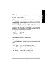
... Conductor Cable Auto If a hard disk IDE2 Conductor Cable Auto controller card is USB Controller USB Key board Support USB Mouse Support AC97 Audio Onboard H/W LAN * Onboard LAN Boot ROM * Onboard Serial Port 1 Onboard Serial Port 2 UART Mode Select x UR2 Duplex Mode Onboard Parallel Port Parallel Port Mode x ECP Mode Use DMA Game Port Address Midi Port Address Midi Port IRQ Enabled Disabled Disabled Auto Enabled Disabled 3F8/IRQ4 2F8/IRQ3 Normal Half 378/IRQ7 SPP 3 201 330 10 used, set at Disable [Enabled] Enable onboard IDE PORT [Disabled] Disable onboard IDE PORT higf: Mov e Enter...
... Conductor Cable Auto If a hard disk IDE2 Conductor Cable Auto controller card is USB Controller USB Key board Support USB Mouse Support AC97 Audio Onboard H/W LAN * Onboard LAN Boot ROM * Onboard Serial Port 1 Onboard Serial Port 2 UART Mode Select x UR2 Duplex Mode Onboard Parallel Port Parallel Port Mode x ECP Mode Use DMA Game Port Address Midi Port Address Midi Port IRQ Enabled Disabled Disabled Auto Enabled Disabled 3F8/IRQ4 2F8/IRQ3 Normal Half 378/IRQ7 SPP 3 201 330 10 used, set at Disable [Enabled] Enable onboard IDE PORT [Disabled] Disable onboard IDE PORT higf: Mov e Enter...
User Manual
Page 34
...our IDE dev ice and cable is compatible w ith ATA66/100). 8ATA33 Set IDE2 Conductor Cable to ATA33 (Please make sure y our IDE dev ice and cable is compatible w ith ATA33). C USB Keyboard Support 8Enabled Enable USB Key board Support. 8Disabled Disable USB Key board Support. (Default v alue) C USB Mouse Support 8Enabled Enable USB Mouse Support. 8Disabled Disable USB Mouse Support. (Default v alue) GA-8LD533 Series Motherboard - 30 - C On-Chip Secondary PCI IDE 8Enabled Enable onboard 2nd channel IDE port. (Default v alue) 8Disabled Disable onboard 2nd channel IDE port.
...our IDE dev ice and cable is compatible w ith ATA66/100). 8ATA33 Set IDE2 Conductor Cable to ATA33 (Please make sure y our IDE dev ice and cable is compatible w ith ATA33). C USB Keyboard Support 8Enabled Enable USB Key board Support. 8Disabled Disable USB Key board Support. (Default v alue) C USB Mouse Support 8Enabled Enable USB Mouse Support. 8Disabled Disable USB Mouse Support. (Default v alue) GA-8LD533 Series Motherboard - 30 - C On-Chip Secondary PCI IDE 8Enabled Enable onboard 2nd channel IDE port. (Default v alue) 8Disabled Disable onboard 2nd channel IDE port.
User Manual
Page 35
... Disabled onboard LAN Boot ROM function.(Default v alue) C Onboard Serial Port 1 8Auto BIOS w ill automatically setup the port 1 address. 83F8/IRQ4 Enable onboard Serial port 1 and address is 3F8. (Default v alue) 82F8/IRQ3 Enable onboard Serial port 1 and address is 2F8. 83E8/IRQ4 Enable onboard Serial port 1 and address is 3E8. 82E8/IRQ3 Enable onboard Serial port 1 and address is 2E8. 8Disabled Disable onboard Serial port 2. C UART Mode Select (This item allows you to determine which Infra Red(IR) function of Onboard I/O chip) 8ASKIR 8IrDA Set onboard I /O chip UART...
... Disabled onboard LAN Boot ROM function.(Default v alue) C Onboard Serial Port 1 8Auto BIOS w ill automatically setup the port 1 address. 83F8/IRQ4 Enable onboard Serial port 1 and address is 3F8. (Default v alue) 82F8/IRQ3 Enable onboard Serial port 1 and address is 2F8. 83E8/IRQ4 Enable onboard Serial port 1 and address is 3E8. 82E8/IRQ3 Enable onboard Serial port 1 and address is 2E8. 8Disabled Disable onboard Serial port 2. C UART Mode Select (This item allows you to determine which Infra Red(IR) function of Onboard I/O chip) 8ASKIR 8IrDA Set onboard I /O chip UART...
User Manual
Page 37
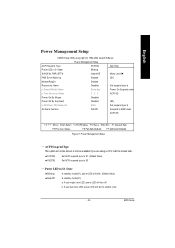
... using a CPU with the locked ratio. 8S1(POS) 8S3(STR) Set ACPI suspend ty pe to S1. (Default Value) Set ACPI suspend ty pe to another color. - 33 - BIOS Setup If use single color LED, pow er LED w ill turn to S3. If use dual color LED, pow er LED w ill turn off. C Power LED i n S1 State 8Blinking In standby mode(S1), pow er LED w ill blink. (Default Value) 8Dual/Off In standby mode...
... using a CPU with the locked ratio. 8S1(POS) 8S3(STR) Set ACPI suspend ty pe to S1. (Default Value) Set ACPI suspend ty pe to another color. - 33 - BIOS Setup If use single color LED, pow er LED w ill turn to S3. If use dual color LED, pow er LED w ill turn off. C Power LED i n S1 State 8Blinking In standby mode(S1), pow er LED w ill blink. (Default Value) 8Dual/Off In standby mode...
User Manual
Page 45
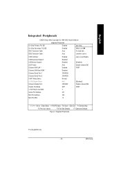
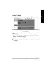
BIOS Setup English Top Performance CMOS Setup Utility -Copy right (C) 1984-2002 Aw ard Softw are }Standard CMOS Features Load Fail-Safe Defaults }Adv anced BIOS Features }Integrated PerTipohperPalesrformance Load Optimized Defaults Set Superv isor Passw ord }Pow er ManagDemiseanbtlSeedtu..p n ] Set User Passw ord }PnP/PCI ConfiEgunraabtiolends Sav e & Ex it Setup }Frequency /Voltage Control Ex it Without Sav ing Top Performance hi: Mov e ESC:Quit F8: Q-Flash ESC: Abort ENTER: Accept F3: Select...
BIOS Setup English Top Performance CMOS Setup Utility -Copy right (C) 1984-2002 Aw ard Softw are }Standard CMOS Features Load Fail-Safe Defaults }Adv anced BIOS Features }Integrated PerTipohperPalesrformance Load Optimized Defaults Set Superv isor Passw ord }Pow er ManagDemiseanbtlSeedtu..p n ] Set User Passw ord }PnP/PCI ConfiEgunraabtiolends Sav e & Ex it Setup }Frequency /Voltage Control Ex it Without Sav ing Top Performance hi: Mov e ESC:Quit F8: Q-Flash ESC: Abort ENTER: Accept F3: Select...
User Manual
Page 48
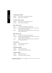
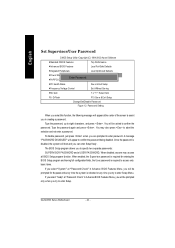
To disable password, just press when you are }Standard CMOS Features Top Performance }Adv anced BIOS Features Load Fail-Safe Defaults }Integrated Peripherals Load Optimized Defaults }Pow er Management Setup Enter Password: }PnP/PCI Configurations Set Superv isor Passw ord Set User Passw ord }PC Health Status Sav e & Ex it Setup }Frequency /Voltage Control Ex it Without Sav ing ESC:Quit higf:Select Item F8: Q-Flash F10:Sav e & Ex it Setup Change/Set/Disable Passw ord Figure...
To disable password, just press when you are }Standard CMOS Features Top Performance }Adv anced BIOS Features Load Fail-Safe Defaults }Integrated Peripherals Load Optimized Defaults }Pow er Management Setup Enter Password: }PnP/PCI Configurations Set Superv isor Passw ord Set User Passw ord }PC Health Status Sav e & Ex it Setup }Frequency /Voltage Control Ex it Without Sav ing ESC:Quit higf:Select Item F8: Q-Flash F10:Sav e & Ex it Setup Change/Set/Disable Passw ord Figure...
User Manual
Page 56
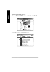
English STEP 3: Download BIOS and BIOS utility program. (1) Please go to Gigabyte website http://www.gigabyte.com.tw/index.html, and click "Support". (2) From Supportzone, click the "Motherboards BIOS & Drivers". GA-8LD533 Series Motherboard - 52 -
English STEP 3: Download BIOS and BIOS utility program. (1) Please go to Gigabyte website http://www.gigabyte.com.tw/index.html, and click "Support". (2) From Supportzone, click the "Motherboards BIOS & Drivers". GA-8LD533 Series Motherboard - 52 -
User Manual
Page 68
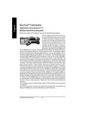
... products supported list in the control panel.Ifusers prefer "Overclock" by Gigabyte. This windows based utilityhas totally changed on the otherhand,they justneed to click "Auto Optimize" to pave the way for future generations. This is the firstwindows based overclocking utility is different from other components. For users who choose "Easy Mode", they can choose either "Easy Mode" or"Advanced Mode" foroverclocking attheir convenience. GA-8LD533 Series Motherboard - 64...
... products supported list in the control panel.Ifusers prefer "Overclock" by Gigabyte. This windows based utilityhas totally changed on the otherhand,they justneed to click "Auto Optimize" to pave the way for future generations. This is the firstwindows based overclocking utility is different from other components. For users who choose "Easy Mode", they can choose either "Easy Mode" or"Advanced Mode" foroverclocking attheir convenience. GA-8LD533 Series Motherboard - 64...
User Manual
Page 78
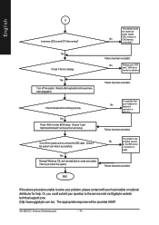
... help. Check if keyboard is display. Then try to enter BIOS setup. Or, you could be provided ASAP. The problem could submit your VGA card / VGA slot or monitor is defective. It is defective. Failure has been excluded. END If the above procedure unable to the service mail via Gigabyte website technical support zone (http://www.gigabyte.com.tw). GA-8LD533 Series Motherboard - 74 - Failure has been excluded. Failure has been excluded...
... help. Check if keyboard is display. Then try to enter BIOS setup. Or, you could be provided ASAP. The problem could submit your VGA card / VGA slot or monitor is defective. It is defective. Failure has been excluded. END If the above procedure unable to the service mail via Gigabyte website technical support zone (http://www.gigabyte.com.tw). GA-8LD533 Series Motherboard - 74 - Failure has been excluded. Failure has been excluded...


