
Manual
Page 6
Optional Accessories Š 2 Ports USB 2.0 Cable (Part Number: 12CR1-1UB030-51/R) Š 4 Ports USB 2.0 Cable (Part Number: 12CR1-1UB030-21/R) Š S/PDIF In and Out Cable (Part Number: 12CR1-1SPINO-11/R) Š e-SATA Cable (Part Number: 12CF1-3SATPW-11R) - 6 - Item Checklist IDE Cable x 1 and FDD Cable x 1 SATA 3Gb/s Cable x 2 I/O Shield * The items listed above are for reference only, and are subject to change without notice.
Optional Accessories Š 2 Ports USB 2.0 Cable (Part Number: 12CR1-1UB030-51/R) Š 4 Ports USB 2.0 Cable (Part Number: 12CR1-1UB030-21/R) Š S/PDIF In and Out Cable (Part Number: 12CR1-1SPINO-11/R) Š e-SATA Cable (Part Number: 12CF1-3SATPW-11R) - 6 - Item Checklist IDE Cable x 1 and FDD Cable x 1 SATA 3Gb/s Cable x 2 I/O Shield * The items listed above are for reference only, and are subject to change without notice.

Manual
Page 9
.... 4. Please do not allow screws to come in contact with the motherboard circuit or its power cord. 2. Instances of Non-Warranty 1. Please verify that all cables and power connectors are uncertain about any installation steps or have these items on top of an antistatic pad or within the computer casing. 6. These... circuits and components which can lead to damage to system components as well as physical harm to the user. 8. Product determined to be an unofficial Gigabyte product. - 9 -
.... 4. Please do not allow screws to come in contact with the motherboard circuit or its power cord. 2. Instances of Non-Warranty 1. Please verify that all cables and power connectors are uncertain about any installation steps or have these items on top of an antistatic pad or within the computer casing. 6. These... circuits and components which can lead to damage to system components as well as physical harm to the user. 8. Product determined to be an unofficial Gigabyte product. - 9 -
Manual
Page 10
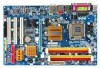
...4 / Celeron® D Š L2 cache varies with CPU Front Side Bus Š Supports 1066/800/533 MHz FSB Chipset Š Northbridge: Intel® 945G Express Chipset Š Southbridge: Intel® ICH7 LAN Š Onboard Realtek RTL8111B chip (10/100/1000 Mbit) Audio Š Onboard Realtek ALC888 chip Š ...panel connector Š 1 front audio connector Š 1 CD In connector Š 1 S/PDIF In/Out connector Š 2 USB 2.0/1.1 connectors for additional 4 ports by cables Š 1 Chassis Intrusion connector Š 1 power LED connector GA-945G-DS3 Motherboard - 10 -
...4 / Celeron® D Š L2 cache varies with CPU Front Side Bus Š Supports 1066/800/533 MHz FSB Chipset Š Northbridge: Intel® 945G Express Chipset Š Southbridge: Intel® ICH7 LAN Š Onboard Realtek RTL8111B chip (10/100/1000 Mbit) Audio Š Onboard Realtek ALC888 chip Š ...panel connector Š 1 front audio connector Š 1 CD In connector Š 1 S/PDIF In/Out connector Š 2 USB 2.0/1.1 connectors for additional 4 ports by cables Š 1 Chassis Intrusion connector Š 1 power LED connector GA-945G-DS3 Motherboard - 10 -
Manual
Page 20
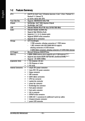
...work if you install it in the wrong direction and sometimes the chip fan will be damaged. Definition 1 GND 1 2 +12V 3 NC GA-945G-DS3 Motherboard - 20 - English 3/4/5) CPU_FAN / SYS_FAN / PWR_FAN (Cooler Fan Power Connector) The cooler fan power connector supplies a +12V power ...Pin No. A red power connector wire indicates a positive connection and requires a +12V power voltage. Remember to connect the CPU/system/power fan cable to the CPU_FAN/SYS_FAN/PWR_FAN connector to prevent CPU damage or system hanging caused by overheating. 1 CPU_FAN 1 SYS_FAN 1 PWR_FAN CPU_FAN : Pin No....
...work if you install it in the wrong direction and sometimes the chip fan will be damaged. Definition 1 GND 1 2 +12V 3 NC GA-945G-DS3 Motherboard - 20 - English 3/4/5) CPU_FAN / SYS_FAN / PWR_FAN (Cooler Fan Power Connector) The cooler fan power connector supplies a +12V power ...Pin No. A red power connector wire indicates a positive connection and requires a +12V power voltage. Remember to connect the CPU/system/power fan cable to the CPU_FAN/SYS_FAN/PWR_FAN connector to prevent CPU damage or system hanging caused by overheating. 1 CPU_FAN 1 SYS_FAN 1 PWR_FAN CPU_FAN : Pin No....

Manual
Page 21
...the IDE connector. 2 40 1 39 - 21 - If you wish to connect two IDE devices, please set the jumper on one IDE cable, and the single IDE cable can then connect to two IDE devices (hard drive or optical drive). Hardware Installation English 7) FDD (Floppy Connector) The FDD connector is used.... One IDE connector can connect to one IDE device as Slave (for information on settings, please refer to the FDD drive. Before attaching the IDE cable, please take note of the foolproof groove in the FDD connector. 33 1 34 2 8) IDE1 (IDE Connector) An IDE device connects to the ...
...the IDE connector. 2 40 1 39 - 21 - If you wish to connect two IDE devices, please set the jumper on one IDE cable, and the single IDE cable can then connect to two IDE devices (hard drive or optical drive). Hardware Installation English 7) FDD (Floppy Connector) The FDD connector is used.... One IDE connector can connect to one IDE device as Slave (for information on settings, please refer to the FDD drive. Before attaching the IDE cable, please take note of the foolproof groove in the FDD connector. 33 1 34 2 8) IDE1 (IDE Connector) An IDE device connects to the ...

Manual
Page 25
...DX+ USB Dy+ GND GND No Pin NC - 25 - Check the pin assignment carefully while you connect the S/PDIF cable, incorrect connection between the cable and connector will make the device unable to work or even damage it . Hardware Installation Check the pin assignment carefully while... you connect the front USB cable, incorrect connection between the cable and connector will make the device unable to an external Dolby Digital Decoder. For optional front USB cable, please contact your stereo system has digital input function. Use S/...
...DX+ USB Dy+ GND GND No Pin NC - 25 - Check the pin assignment carefully while you connect the S/PDIF cable, incorrect connection between the cable and connector will make the device unable to work or even damage it . Hardware Installation Check the pin assignment carefully while... you connect the front USB cable, incorrect connection between the cable and connector will make the device unable to an external Dolby Digital Decoder. For optional front USB cable, please contact your stereo system has digital input function. Use S/...

Manual
Page 37
... USB keyboard support. Azalia Codec Auto Auto detect Azalia audio function. (Default value) Disabled Disable Azalia audio function. Enabled BIOS will detect cabling issue and report the approximate distance to the fault or short. Pair1-2 Status = Pair3-6 Status = Pair4-5 Status = Pair7-8 Status...PU/PD: Value F10: Save F6: Fail-Safe Defaults ESC: Exit F1: General Help F7: Optimized Defaults This motherboard incorporates cable diagnostic feature designed to the motherboard, the Status fields of all USB storage devices. (Default value) Disabled Disable this function. ...
... USB keyboard support. Azalia Codec Auto Auto detect Azalia audio function. (Default value) Disabled Disable Azalia audio function. Enabled BIOS will detect cabling issue and report the approximate distance to the fault or short. Pair1-2 Status = Pair3-6 Status = Pair4-5 Status = Pair7-8 Status...PU/PD: Value F10: Save F6: Fail-Safe Defaults ESC: Exit F1: General Help F7: Optimized Defaults This motherboard incorporates cable diagnostic feature designed to the motherboard, the Status fields of all USB storage devices. (Default value) Disabled Disable this function. ...
Manual
Page 38
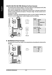
...DOS mode; Disabled Disable onboard Serial port 1. Enable onboard LPT port and address is 278/IRQ5. Link Detected --> 100Mbps Cable Length= 30m When LAN Cable Is Functioning Normally... When a Cable Problem Occurs... Example: Pair1-2 Status = Short / Length = 1.6m Explanation: A fault or short might occur at... onboard Serial port 1 and address is 2F8/IRQ3. 3E8/IRQ4 2E8/IRQ3 Enable onboard Serial port 1 and address is 3E8/IRQ4. GA-945G-DS3 Motherboard - 38 - ECP ECP+EPP Using Parallel port as ECP & EPP mode. Disabled Disable this function. Enable onboard LPT port ...
...DOS mode; Disabled Disable onboard Serial port 1. Enable onboard LPT port and address is 278/IRQ5. Link Detected --> 100Mbps Cable Length= 30m When LAN Cable Is Functioning Normally... When a Cable Problem Occurs... Example: Pair1-2 Status = Short / Length = 1.6m Explanation: A fault or short might occur at... onboard Serial port 1 and address is 2F8/IRQ3. 3E8/IRQ4 2E8/IRQ3 Enable onboard Serial port 1 and address is 3E8/IRQ4. GA-945G-DS3 Motherboard - 38 - ECP ECP+EPP Using Parallel port as ECP & EPP mode. Disabled Disable this function. Enable onboard LPT port ...

Manual
Page 43
... temperature. PWM Set to Voltage when you use a CPU fan with a 4-pin fan power cable. Note: In fact, the Voltage option can adjust the fan speed with 3-pin or 4-pin power cables. BIOS Setup With such CPU fans, selecting PWM will run at different speed depending on their ...Control is enabled, CPU fan will not effectively reduce the fan speed. - 43 - Enabled When this function. However, some 4-pin CPU fan power cables are not designed following Intel 4-Wire fans PWM control specifications. Users can be used for it. (Default value) Voltage Set to PWM when you ...
... temperature. PWM Set to Voltage when you use a CPU fan with a 4-pin fan power cable. Note: In fact, the Voltage option can adjust the fan speed with 3-pin or 4-pin power cables. BIOS Setup With such CPU fans, selecting PWM will run at different speed depending on their ...Control is enabled, CPU fan will not effectively reduce the fan speed. - 43 - Enabled When this function. However, some 4-pin CPU fan power cables are not designed following Intel 4-Wire fans PWM control specifications. Users can be used for it. (Default value) Voltage Set to PWM when you ...
Manual
Page 62
... motherboard and the surround cable, a small window will pop up and ask you can also find an Audio Manager icon in Control Panel). STEP 3: Connect the 4-channel speakers to open the Audio Control Panel. The 4channel audio setup is connected. In the upper left list, click 4CH Speaker. GA-945G-DS3 Motherboard - 62 - STEP...
... motherboard and the surround cable, a small window will pop up and ask you can also find an Audio Manager icon in Control Panel). STEP 3: Connect the 4-channel speakers to open the Audio Control Panel. The 4channel audio setup is connected. In the upper left list, click 4CH Speaker. GA-945G-DS3 Motherboard - 62 - STEP...

Manual
Page 63
Appendix English In the upper left list, click 6CH Speaker. Choose a device depending on the motherboard and the surround cable, a small window will pop up and ask you can also find the icon in your system tray (you what type of Front Speaker Out (Line ...
Appendix English In the upper left list, click 6CH Speaker. Choose a device depending on the motherboard and the surround cable, a small window will pop up and ask you can also find the icon in your system tray (you what type of Front Speaker Out (Line ...
Manual
Page 64
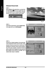
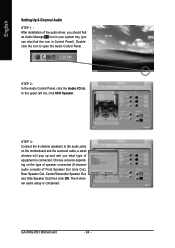
... the audio jacks on the type of speaker connected (8-channel audio consists of equipment is completed. Choose a device depending on the motherboard and the surround cable, a small window will pop up and ask you can also find an Audio Manager icon in your system tray (you what type of Front Speaker... Panel). In the upper left list, click 8CH Speaker. The 8-channel audio setup is connected. STEP 2: In the Audio Control Panel, click the Audio I/O tab. GA-945G-DS3 Motherboard - 64 - STEP 3: Connect the 8-channel speakers to open the Audio Control Panel.
... the audio jacks on the type of speaker connected (8-channel audio consists of equipment is completed. Choose a device depending on the motherboard and the surround cable, a small window will pop up and ask you can also find an Audio Manager icon in your system tray (you what type of Front Speaker... Panel). In the upper left list, click 8CH Speaker. The 8-channel audio setup is connected. STEP 2: In the Audio Control Panel, click the Audio I/O tab. GA-945G-DS3 Motherboard - 64 - STEP 3: Connect the 8-channel speakers to open the Audio Control Panel.


