Manual
Page 4
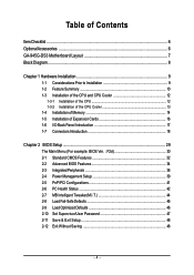
... ...6 GA-945G-DS3 Motherboard Layout 7 Block Diagram ...8 Chapter 1 Hardware Installation 9 1-1 Considerations Prior to Installation 9 1-2 Feature Summary 10 1-3 Installation of the CPU and CPU Cooler 12 1-3-1 Installation of the CPU 12 1-3-2 Installation of the CPU Cooler 13 1-4 Installation of Memory 14 1-5 Installation of Expansion Cards 16 1-6 I/O Back Panel Introduction 17 1-7 Connectors Introduction 18 Chapter 2 BIOS Setup 29 The Main Menu (For example: BIOS Ver. : F2d 30 2-1 Standard CMOS Features 32 2-2 Advanced BIOS Features 34 2-3 IntegratedPeripherals 36 2-4 Power...
... ...6 GA-945G-DS3 Motherboard Layout 7 Block Diagram ...8 Chapter 1 Hardware Installation 9 1-1 Considerations Prior to Installation 9 1-2 Feature Summary 10 1-3 Installation of the CPU and CPU Cooler 12 1-3-1 Installation of the CPU 12 1-3-2 Installation of the CPU Cooler 13 1-4 Installation of Memory 14 1-5 Installation of Expansion Cards 16 1-6 I/O Back Panel Introduction 17 1-7 Connectors Introduction 18 Chapter 2 BIOS Setup 29 The Main Menu (For example: BIOS Ver. : F2d 30 2-1 Standard CMOS Features 32 2-2 Advanced BIOS Features 34 2-3 IntegratedPeripherals 36 2-4 Power...
Manual
Page 10
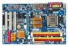
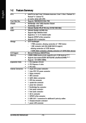
... 3 PCI slots Internal Connectors Š 1 24-pin ATX power connector Š 1 4-pin ATX 12V power connector Š 1 floppy connector Š 1 IDE connector Š 4 SATA 3Gb/s connectors Š 1 CPU fan connector Š 1 system fan connector Š 1 power fan connector Š 1 Northbridge fan connector Š 1 front panel connector Š 1 front audio connector Š 1 CD In connector Š 1 S/PDIF In/Out connector Š 2 USB 2.0/1.1 connectors for additional 4 ports by cables Š 1 Chassis Intrusion connector Š 1 power LED connector GA-945G-DS3 Motherboard...
... 3 PCI slots Internal Connectors Š 1 24-pin ATX power connector Š 1 4-pin ATX 12V power connector Š 1 floppy connector Š 1 IDE connector Š 4 SATA 3Gb/s connectors Š 1 CPU fan connector Š 1 system fan connector Š 1 power fan connector Š 1 Northbridge fan connector Š 1 front panel connector Š 1 front audio connector Š 1 CD In connector Š 1 S/PDIF In/Out connector Š 2 USB 2.0/1.1 connectors for additional 4 ports by cables Š 1 Chassis Intrusion connector Š 1 power LED connector GA-945G-DS3 Motherboard...

Manual
Page 13
... or using extreme care when removing the CPU cooler. - 13 - Fig. 6 Finally, please attach the power connector of the CPU cooler to the pin hole on the surface of the installed CPU. Hardware Installation The CPU cooler may adhere to the CPU cooler installation section of the user manual) Fig. 5 Please check the back of motherboard after installing. If the push pin is complete. English 1-3-2 Installation of the CPU Cooler...
... or using extreme care when removing the CPU cooler. - 13 - Fig. 6 Finally, please attach the power connector of the CPU cooler to the pin hole on the surface of the installed CPU. Hardware Installation The CPU cooler may adhere to the CPU cooler installation section of the user manual) Fig. 5 Please check the back of motherboard after installing. If the push pin is complete. English 1-3-2 Installation of the CPU Cooler...
Manual
Page 15
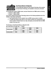
English Dual Channel Memory Configuration The GA-945G-DS3 supports the Dual Channel Technology. After operating the Dual Channel Technology, the bandwidth of Intel chipset specifications. 1. The GA-945G-DS3 includes 4 DIMM sockets, and each Channel has two DIMM sockets as following: Channel 0 : DDRII1, DDRII2 Channel 1 : DDRII3, DDRII4 If you must install them into DIMM sockets of the same color. To enable Dual Channel mode with two or four memory modules (it is recommended to the limitation of memory bus will not be enabled if...
English Dual Channel Memory Configuration The GA-945G-DS3 supports the Dual Channel Technology. After operating the Dual Channel Technology, the bandwidth of Intel chipset specifications. 1. The GA-945G-DS3 includes 4 DIMM sockets, and each Channel has two DIMM sockets as following: Channel 0 : DDRII1, DDRII2 Channel 1 : DDRII3, DDRII4 If you must install them into DIMM sockets of the same color. To enable Dual Channel mode with two or four memory modules (it is recommended to the limitation of memory bus will not be enabled if...

Manual
Page 18
... 1) ATX_12V 2) ATX (Power Connector) 3) CPU_FAN 4) SYS_FAN 5) PWR_FAN 6) NB_FAN 7) FDD 8) IDE1 9) SATAII0/1/2/3 10) PWR_LED 11) F_PANEL 12) F_AUDIO 13) CD_IN 14) SPDIF_IO 15) F_USB1 / F_USB2 16) CI 17) CLR_CMOS 18) BATTERY GA-945G-DS3 Motherboard - 18 - English MIC In The default MIC In jack. Please refer to perform different functions via the audio software. Only microphones still MUST be connected to the default Mic...
... 1) ATX_12V 2) ATX (Power Connector) 3) CPU_FAN 4) SYS_FAN 5) PWR_FAN 6) NB_FAN 7) FDD 8) IDE1 9) SATAII0/1/2/3 10) PWR_LED 11) F_PANEL 12) F_AUDIO 13) CD_IN 14) SPDIF_IO 15) F_USB1 / F_USB2 16) CI 17) CLR_CMOS 18) BATTERY GA-945G-DS3 Motherboard - 18 - English MIC In The default MIC In jack. Please refer to perform different functions via the audio software. Only microphones still MUST be connected to the default Mic...
Manual
Page 20
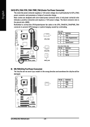
... GA-945G-DS3 Motherboard - 20 - Most coolers are designed with color-coded power connector wires. Remember to connect the CPU/system/power fan cable to the CPU_FAN/SYS_FAN/PWR_FAN connector to prevent CPU damage or system hanging caused by overheating. 1 CPU_FAN 1 SYS_FAN 1 PWR_FAN CPU_FAN : Pin No. 1 2 3 4 Definition GND +12V / Speed Control Sense Speed Control SYS_FAN / PWR_FAN : Pin No. English 3/4/5) CPU_FAN / SYS_FAN / PWR_FAN (Cooler Fan Power Connector) The cooler fan power connector supplies a +12V power voltage via a 3-pin/4-pin(only for CPU_FAN) power connector and...
... GA-945G-DS3 Motherboard - 20 - Most coolers are designed with color-coded power connector wires. Remember to connect the CPU/system/power fan cable to the CPU_FAN/SYS_FAN/PWR_FAN connector to prevent CPU damage or system hanging caused by overheating. 1 CPU_FAN 1 SYS_FAN 1 PWR_FAN CPU_FAN : Pin No. 1 2 3 4 Definition GND +12V / Speed Control Sense Speed Control SYS_FAN / PWR_FAN : Pin No. English 3/4/5) CPU_FAN / SYS_FAN / PWR_FAN (Cooler Fan Power Connector) The cooler fan power connector supplies a +12V power voltage via a 3-pin/4-pin(only for CPU_FAN) power connector and...

Manual
Page 21
... (IDE Connector) An IDE device connects to the computer via an IDE connector. One IDE connector can connect to one IDE device as Master and the other end of FDD drives supported are: 360 KB, 720 KB, 1.2 MB, 1.44 MB and 2.88 MB. The types of the cable connects to two IDE devices (hard drive or optical drive). If you wish to connect two IDE devices, please set the jumper on one IDE cable, and the single IDE cable can then connect...
... (IDE Connector) An IDE device connects to the computer via an IDE connector. One IDE connector can connect to one IDE device as Master and the other end of FDD drives supported are: 360 KB, 720 KB, 1.2 MB, 1.44 MB and 2.88 MB. The types of the cable connects to two IDE devices (hard drive or optical drive). If you wish to connect two IDE devices, please set the jumper on one IDE cable, and the single IDE cable can then connect...
Manual
Page 22
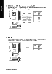
... the system enters suspend mode(S1). GA-945G-DS3 Motherboard - 22 - SATAII0 7 1 SATAII2 7 1 1 7 SATAII1 1 7 SATAII3 Pin No. 1 2 3 4 5 6 7 Definition GND TXP TXN GND RXN RXP GND 10) PWR_LED The PWR_LED connector is on/off. Please refer to the BIOS setting for the SATA 3Gb/s and install the proper driver in order to indicate whether the system is connected with the system power indicator to work properly. Pin No...
... the system enters suspend mode(S1). GA-945G-DS3 Motherboard - 22 - SATAII0 7 1 SATAII2 7 1 1 7 SATAII1 1 7 SATAII3 Pin No. 1 2 3 4 5 6 7 Definition GND TXP TXN GND RXN RXP GND 10) PWR_LED The PWR_LED connector is on/off. Please refer to the BIOS setting for the SATA 3Gb/s and install the proper driver in order to indicate whether the system is connected with the system power indicator to work properly. Pin No...

Manual
Page 23
RESRES+ NC Reset Switch IDE Hard Disk Active LED MSG (Message LED/Power/Sleep LED) (Yellow) PW (Power Switch) (Red) SPEAK (Speaker Connector) (Amber) HD (IDE Hard Disk Active LED) (Blue) RES (Reset Switch) (Green) NC ( Purple) Pin 1: LED anode(+) Pin 2: LED cathode(-) Open: Normal Close: Power On/Off Pin 1: Power Pin 2- Pin 3: NC Pin 4: Data(-) Pin 1: LED anode(+) Pin 2: LED cathode(-) Open: Normal Close: Reset Hardware System NC - 23 - PW+ PWSPEAK+ SPEAK- 2 20 1 19 HD+ HD- Message LED/ Power/ Sleep LED Power Switch Speaker Connector MSG+ MSG- of your chassis front panel to the...
RESRES+ NC Reset Switch IDE Hard Disk Active LED MSG (Message LED/Power/Sleep LED) (Yellow) PW (Power Switch) (Red) SPEAK (Speaker Connector) (Amber) HD (IDE Hard Disk Active LED) (Blue) RES (Reset Switch) (Green) NC ( Purple) Pin 1: LED anode(+) Pin 2: LED cathode(-) Open: Normal Close: Power On/Off Pin 1: Power Pin 2- Pin 3: NC Pin 4: Data(-) Pin 1: LED anode(+) Pin 2: LED cathode(-) Open: Normal Close: Reset Hardware System NC - 23 - PW+ PWSPEAK+ SPEAK- 2 20 1 19 HD+ HD- Message LED/ Power/ Sleep LED Power Switch Speaker Connector MSG+ MSG- of your chassis front panel to the...
Manual
Page 24
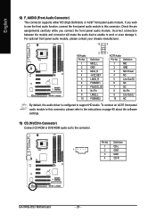
... the software settings. 13) CD_IN (CD In Connector) Connect CD-ROM or DVD-ROM audio out to support HD Audio. Pin No. Check the pin assignments carefully while you wish to use the front audio function, connect the front panel audio module to work or even damage it. Definition 1 MIC 2 GND 3 MIC Power 4 NC 5 Line Out (R) 6 NC 7 NC 8 No Pin 9 Line Out (L) 10 NC By default, the audio driver is configured to the connector. To connect...
... the software settings. 13) CD_IN (CD In Connector) Connect CD-ROM or DVD-ROM audio out to support HD Audio. Pin No. Check the pin assignments carefully while you wish to use the front audio function, connect the front panel audio module to work or even damage it. Definition 1 MIC 2 GND 3 MIC Power 4 NC 5 Line Out (R) 6 NC 7 NC 8 No Pin 9 Line Out (L) 10 NC By default, the audio driver is configured to the connector. To connect...
Manual
Page 32
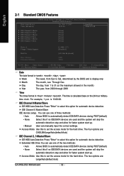
...- Access Mode Use this to automatically detect IDE/SATA devices during POST(default) Select this option for faster system start up . English 2-1 Standard CMOS Features Date (mm:dd:yy) Time (hh:mm:ss) CMOS Setup Utility-Copyright (C) 1984-2007 Award Software Standard CMOS Features Tue, Feb 13 2007 18:25:04 Item Help Menu Level` ` IDE Channel 0 Master ` IDE Channel 0 Slave ` IDE Channel 2 Master ` IDE Channel 2 Slave ` IDE Channel 3 Master ` IDE Channel 3 Slave [None] [None] [None] [None] [None] [None] Drive A Floppy 3 Mode Support Halt...
...- Access Mode Use this to automatically detect IDE/SATA devices during POST(default) Select this option for faster system start up . English 2-1 Standard CMOS Features Date (mm:dd:yy) Time (hh:mm:ss) CMOS Setup Utility-Copyright (C) 1984-2007 Award Software Standard CMOS Features Tue, Feb 13 2007 18:25:04 Item Help Menu Level` ` IDE Channel 0 Master ` IDE Channel 0 Slave ` IDE Channel 2 Master ` IDE Channel 2 Slave ` IDE Channel 3 Master ` IDE Channel 3 Slave [None] [None] [None] [None] [None] [None] Drive A Floppy 3 Mode Support Halt...

Manual
Page 37
... users to decide whether to detect the status of wires will detect cabling issue and report the approximate distance to the following information for diagnosing your LAN cable: When No LAN Cable Is Attached... BIOS Setup Enabled Enable USB 2.0 controller. (Default value) Disabled Disable USB 2.0 controller. SMART LAN CMOS Setup Utility-Copyright (C) 1984-2007 Award Software SMART LAN Start detecting at Port..... USB Keyboard Support Enabled Enable USB keyboard support. Enabled BIOS will scan all four pairs of the attached LAN cable. Refer to the fault or short...
... users to decide whether to detect the status of wires will detect cabling issue and report the approximate distance to the following information for diagnosing your LAN cable: When No LAN Cable Is Attached... BIOS Setup Enabled Enable USB 2.0 controller. (Default value) Disabled Disable USB 2.0 controller. SMART LAN CMOS Setup Utility-Copyright (C) 1984-2007 Award Software SMART LAN Start detecting at Port..... USB Keyboard Support Enabled Enable USB keyboard support. Enabled BIOS will scan all four pairs of the attached LAN cable. Refer to the fault or short...

Manual
Page 42
... / 176oF. GA-945G-DS3 Motherboard - 42 - Monitor CPU temperature at 70oC / 158oF. Monitor CPU temperature at next boot. Disable this function. (Default value) CPU/POWER/SYSTEM FAN Fail Warning Disabled Enabled Disable the fan fail warning function. (Default value) Enable the fan fail warning function. Current CPU Temperature Detect CPU temperature automatically. Current CPU/POWER/SYSTEM FAN Speed (RPM) Detect CPU/Power/System fan speed status automatically. If you want to reset "Case Opened" value, set "Reset Case Open Status" to "Enabled" and save CMOS, your computer...
... / 176oF. GA-945G-DS3 Motherboard - 42 - Monitor CPU temperature at 70oC / 158oF. Monitor CPU temperature at next boot. Disable this function. (Default value) CPU/POWER/SYSTEM FAN Fail Warning Disabled Enabled Disable the fan fail warning function. (Default value) Enable the fan fail warning function. Current CPU Temperature Detect CPU temperature automatically. Current CPU/POWER/SYSTEM FAN Speed (RPM) Detect CPU/Power/System fan speed status automatically. If you want to reset "Case Opened" value, set "Reset Case Open Status" to "Enabled" and save CMOS, your computer...

Manual
Page 45
... FSB voltage by DRAM SPD data). Normal CPU Vcore Display your system is highly dependent on CPUs. (Default value: Normal) Please note that if your CPU's normal voltage. - 45 - for automatic system restart or clear the CMOS setup data and perform a safe restart. For power End-User use a 533 MHz FSB processor, set memory frequency by 0.1V to 100 MHz. PCI Express Frequency Auto Set PCI Express frequency automatically. (Default value) SYC PCI Express frequency SYC with CPU. Warning: Stability is overclocked and...
... FSB voltage by DRAM SPD data). Normal CPU Vcore Display your system is highly dependent on CPUs. (Default value: Normal) Please note that if your CPU's normal voltage. - 45 - for automatic system restart or clear the CMOS setup data and perform a safe restart. For power End-User use a 533 MHz FSB processor, set memory frequency by 0.1V to 100 MHz. PCI Express Frequency Auto Set PCI Express frequency automatically. (Default value) SYC PCI Express frequency SYC with CPU. Warning: Stability is overclocked and...

Manual
Page 47
.../User Password CMOS Setup Utility-Copyright (C) 1984-2007 Award Software ` Standard CMOS Features ` Advanced BIOS Features ` Integrated Peripherals ` Power Management Setup ` PnP/PCI ConfiguratioEnsnter Password: ` PC Health Status ` MB Intelligent Tweaker(M.I.T.) Load Fail-Safe Defaults Load Optimized Defaults Set Supervisor Password Set User Password Save & Exit Setup Exit Without Saving ESC: Quit F8: Q-Flash KLJI: Select Item F10: Save & Exit Setup Change/Set/Disable Password When you select this function, the following message will appear at the center of the screen...
.../User Password CMOS Setup Utility-Copyright (C) 1984-2007 Award Software ` Standard CMOS Features ` Advanced BIOS Features ` Integrated Peripherals ` Power Management Setup ` PnP/PCI ConfiguratioEnsnter Password: ` PC Health Status ` MB Intelligent Tweaker(M.I.T.) Load Fail-Safe Defaults Load Optimized Defaults Set Supervisor Password Set User Password Save & Exit Setup Exit Without Saving ESC: Quit F8: Q-Flash KLJI: Select Item F10: Save & Exit Setup Change/Set/Disable Password When you select this function, the following message will appear at the center of the screen...

Manual
Page 49
English Chapter 3 Install Drivers Pictures below are shown in "Universal Serial Bus controller" under Windows XP operating system, please use Windows Service Pack. Please pick the item that came with your motherboard into your CD-ROM drive, the driver CD-title will scan automatically the system and then list all items defaulted. System will show the installation guide. After restarting your system automatically. After install Windows Service Pack, it will reboot...
English Chapter 3 Install Drivers Pictures below are shown in "Universal Serial Bus controller" under Windows XP operating system, please use Windows Service Pack. Please pick the item that came with your motherboard into your CD-ROM drive, the driver CD-title will scan automatically the system and then list all items defaulted. System will show the installation guide. After restarting your system automatically. After install Windows Service Pack, it will reboot...

Manual
Page 54
... Initial access by booting from CD-ROM and subsequent access by pressing the key in the bottom left corner of OS and all required drivers as well as software. Intel 945 BIOS for the first time, it will stay permanent in your CD-ROM drive. Boot from CD-ROM. System requirements: 1. Save the settings and exit the BIOS Setup. VESA-supported VGA cards How to boot from CD/DVD: Award Modular BIOS...
... Initial access by booting from CD-ROM and subsequent access by pressing the key in the bottom left corner of OS and all required drivers as well as software. Intel 945 BIOS for the first time, it will stay permanent in your CD-ROM drive. Boot from CD-ROM. System requirements: 1. Save the settings and exit the BIOS Setup. VESA-supported VGA cards How to boot from CD/DVD: Award Modular BIOS...
Manual
Page 56
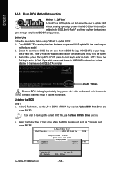
...:Reset :Power Off HDD 0-0 Total size : 0 F5 : Refresh GA-945G-DS3 Motherboard Free size : 0 DEL : Delete - 56 - b. Q-Flash Utility v2.02 Flash Type/Size MXIC SPI Serial Fla 512K Keep DMI Data Enable Update BIOS from the hassles of going through complicated BIOS flashing process. Before Use: Follow the steps below before using FAT32/16/12 file system. 3. English 4-1-3 Flash BIOS Method Introduction Method 1 : Q-FlashTM Q-FlashTM is a BIOS update tool that matches your floppy disk or hard disk. Intel 945 BIOS for 945G-DS3 F2d . . . . : BIOS Setup/Q-Flash...
...:Reset :Power Off HDD 0-0 Total size : 0 F5 : Refresh GA-945G-DS3 Motherboard Free size : 0 DEL : Delete - 56 - b. Q-Flash Utility v2.02 Flash Type/Size MXIC SPI Serial Fla 512K Keep DMI Data Enable Update BIOS from the hassles of going through complicated BIOS flashing process. Before Use: Follow the steps below before using FAT32/16/12 file system. 3. English 4-1-3 Flash BIOS Method Introduction Method 1 : Q-FlashTM Q-FlashTM is a BIOS update tool that matches your floppy disk or hard disk. Intel 945 BIOS for 945G-DS3 F2d . . . . : BIOS Setup/Q-Flash...
Manual
Page 58
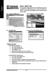
... automatically download and update the BIOS. Installation Complete and Run @BIOS Click Start/ Programs/ Gigabyte/ BIOS/ @BIOS Select @BIOS item than click Install Fig 3. Click "Update New BIOS" c. d. Just select the desired @BIOS server to update their BIOS under Windows. Do not click "Internet Update" icon b. The @BIOS Utility Fig 4. Click "Update New BIOS" icon c . II. Fig 1. Please search for BIOS unzip file, downloading from internet or any other methods (such as: 945GDS3.F2). GA-945G-DS3 Motherboard - 58...
... automatically download and update the BIOS. Installation Complete and Run @BIOS Click Start/ Programs/ Gigabyte/ BIOS/ @BIOS Select @BIOS item than click Install Fig 3. Click "Update New BIOS" c. d. Just select the desired @BIOS server to update their BIOS under Windows. Do not click "Internet Update" icon b. The @BIOS Utility Fig 4. Click "Update New BIOS" icon c . II. Fig 1. Please search for BIOS unzip file, downloading from internet or any other methods (such as: 945GDS3.F2). GA-945G-DS3 Motherboard - 58...
Manual
Page 66
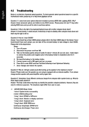
...Question 4: Why do I still get a weak sound after turning up . If not, please change another speaker with an internal amplifier. The situations might differ from MB. 3. AWARD BIOS Beep Codes 1 short: System boots successfully 2 short: CMOS setting error 1 long 1 short: DRAM or M/B error 1 long 2 short: Monitor or display card error 1 long 3 short: Keyboard error 1 long 9 short: BIOS ROM error Continuous long beeps: DRAM error Continuous short beeps: Power error GA-945G-DS3 Motherboard - 66 - Why? Re-insert the battery to see some boards, a small amount of electricity is kept on...
...Question 4: Why do I still get a weak sound after turning up . If not, please change another speaker with an internal amplifier. The situations might differ from MB. 3. AWARD BIOS Beep Codes 1 short: System boots successfully 2 short: CMOS setting error 1 long 1 short: DRAM or M/B error 1 long 2 short: Monitor or display card error 1 long 3 short: Keyboard error 1 long 9 short: BIOS ROM error Continuous long beeps: DRAM error Continuous short beeps: Power error GA-945G-DS3 Motherboard - 66 - Why? Re-insert the battery to see some boards, a small amount of electricity is kept on...


