Manual
Page 4
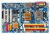
Table of Contents ItemChecklist ...6 OptionalAccessories ...6 GA-945G-DS3 Motherboard Layout 7 Block Diagram ...8 Chapter 1 Hardware Installation 9 1-1 Considerations Prior to Installation 9 1-2 Feature Summary 10 1-3 Installation of the CPU and CPU... 13 1-4 Installation of Memory 14 1-5 Installation of Expansion Cards 16 1-6 I/O Back Panel Introduction 17 1-7 Connectors Introduction 18 Chapter 2 BIOS Setup 29 The Main Menu (For example: BIOS Ver. : F2d 30 2-1 Standard CMOS Features 32 2-2 Advanced BIOS Features 34 2-3 IntegratedPeripherals 36 2-4 Power Management Setup 39 2-5...
Table of Contents ItemChecklist ...6 OptionalAccessories ...6 GA-945G-DS3 Motherboard Layout 7 Block Diagram ...8 Chapter 1 Hardware Installation 9 1-1 Considerations Prior to Installation 9 1-2 Feature Summary 10 1-3 Installation of the CPU and CPU... 13 1-4 Installation of Memory 14 1-5 Installation of Expansion Cards 16 1-6 I/O Back Panel Introduction 17 1-7 Connectors Introduction 18 Chapter 2 BIOS Setup 29 The Main Menu (For example: BIOS Ver. : F2d 30 2-1 Standard CMOS Features 32 2-2 Advanced BIOS Features 34 2-3 IntegratedPeripherals 36 2-4 Power Management Setup 39 2-5...

Manual
Page 19
... connector, the power supply can lead to an unstable system or a system that is able to handle the system voltage requirements. The ATX_12V power connector mainly supplies power to all components and devices are properly installed. If a power supply is used (300W or greater).
... connector, the power supply can lead to an unstable system or a system that is able to handle the system voltage requirements. The ATX_12V power connector mainly supplies power to all components and devices are properly installed. If a power supply is used (300W or greater).

Manual
Page 29
...to the CMOS SETUP screen. When the power is turned on the motherboard supplies the necessary power to use and the possible selections for Main Menu Main Menu The on-line description of the highlighted setup function is turned off, the battery on , press the button during the BIOS POST ...value from the Internet. When the power is displayed at the bottom of the motherboard. CONTROL KEYS Enter> Move to a new BIOS, either GIGABYTE's Q-Flash or @BIOS utility can enter the BIOS setup screen by pressing "Ctrl + F1". If you to activate certain system features.
...to the CMOS SETUP screen. When the power is turned on the motherboard supplies the necessary power to use and the possible selections for Main Menu Main Menu The on-line description of the highlighted setup function is turned off, the battery on , press the button during the BIOS POST ...value from the Internet. When the power is displayed at the bottom of the motherboard. CONTROL KEYS Enter> Move to a new BIOS, either GIGABYTE's Q-Flash or @BIOS utility can enter the BIOS setup screen by pressing "Ctrl + F1". If you to activate certain system features.

Manual
Page 30
... you enter Award BIOS CMOS Setup Utility, the Main Menu (as usual. Select the Load Optimized Defaults item in this chapter are for reference only and may differ from the exact settings for stability. 3. This action makes the system reset to access advanced options. 2. GA-945G-DS3 Motherboard - 30 - CMOS Setup Utility-Copyright (C)... to enter the Xpress Recovery2 screen. : Boot Menu Press the F12 key to enter Boot Menu to accept or enter the sub-menu. The Main Menu (For example: BIOS Ver. : F2d) Once you want, press "Ctrl+F1" to the default settings for your motherboard.
... you enter Award BIOS CMOS Setup Utility, the Main Menu (as usual. Select the Load Optimized Defaults item in this chapter are for reference only and may differ from the exact settings for stability. 3. This action makes the system reset to access advanced options. 2. GA-945G-DS3 Motherboard - 30 - CMOS Setup Utility-Copyright (C)... to enter the Xpress Recovery2 screen. : Boot Menu Press the F12 key to enter Boot Menu to accept or enter the sub-menu. The Main Menu (For example: BIOS Ver. : F2d) Once you want, press "Ctrl+F1" to the default settings for your motherboard.

Manual
Page 55
...IDE channel 3 f. SATA IDE channel 4 Precautions: 1. Please contact your hard disk. (This button will not appear if there is recom- REBOOT: Exit the main screen and restart the system. PATA IDE primary channel b. BACKUP: Back up ) 4. Not compatible to release disk space. (This button will store the backup...Windows 2000, be backed up data from the driver CD before data backup. 2. It is no backup file.) 2. Appendix English The Main Screen of the hard disk, so free space available on the hard disk for Xpress Recovery2 to correctly identify RAID and SATA IDE mode....
...IDE channel 3 f. SATA IDE channel 4 Precautions: 1. Please contact your hard disk. (This button will not appear if there is recom- REBOOT: Exit the main screen and restart the system. PATA IDE primary channel b. BACKUP: Back up ) 4. Not compatible to release disk space. (This button will store the backup...Windows 2000, be backed up data from the driver CD before data backup. 2. It is no backup file.) 2. Appendix English The Main Screen of the hard disk, so free space available on the hard disk for Xpress Recovery2 to correctly identify RAID and SATA IDE mode....

Manual
Page 57
... complete. - 57 - Step 3: When the update process is complete, press any kEeySCto:Rceosnettinue F10:Power Off Step 4: Press ESC and then ENTER to the Q-Flash main menu. CopUypBdaItOeSBcIoOmSpflreotemd D- System will re-detect all peripherals devices after BIOS update, so we recommend that you will see the new BIOS version during POST...
... complete. - 57 - Step 3: When the update process is complete, press any kEeySCto:Rceosnettinue F10:Power Off Step 4: Press ESC and then ENTER to the Q-Flash main menu. CopUypBdaItOeSBcIoOmSpflreotemd D- System will re-detect all peripherals devices after BIOS update, so we recommend that you will see the new BIOS version during POST...