

Manual
Page 1
GA-945GZM-S2 Intel® CoreTM 2 Extreme dual-core / CoreTM 2 Duo / Intel® Pentium® D / Pentium® 4 / Celeron® D LGA775 Processor Motherboard User's Manual Rev. 6601 12ME-945GZMS2-6601R * The WEEE marking on the product indicates this product must not be disposed of with user's other household waste and must be handed over to a designated collection point for the recycling of waste electrical and electronic equipment!! * The WEEE marking applies only in European Union's member states.
GA-945GZM-S2 Intel® CoreTM 2 Extreme dual-core / CoreTM 2 Duo / Intel® Pentium® D / Pentium® 4 / Celeron® D LGA775 Processor Motherboard User's Manual Rev. 6601 12ME-945GZMS2-6601R * The WEEE marking on the product indicates this product must not be disposed of with user's other household waste and must be handed over to a designated collection point for the recycling of waste electrical and electronic equipment!! * The WEEE marking applies only in European Union's member states.

Manual
Page 2
Motherboard GA-945GZM-S2 Jan. 12, 2007 Motherboard GA-945GZM-S2 Jan. 12, 2007
Motherboard GA-945GZM-S2 Jan. 12, 2007 Motherboard GA-945GZM-S2 Jan. 12, 2007

Manual
Page 4
Table of Contents ItemChecklist ...6 OptionalAccessories ...6 GA-945GZM-S2 Motherboard Layout 7 Block Diagram ...8 Chapter 1 Hardware Installation 9 1-1 Considerations Prior to Installation 9 1-2 Feature Summary 10 1-3 Installation of the CPU and CPU Cooler 12 1-3-1 Installation of the CPU ...
Table of Contents ItemChecklist ...6 OptionalAccessories ...6 GA-945GZM-S2 Motherboard Layout 7 Block Diagram ...8 Chapter 1 Hardware Installation 9 1-1 Considerations Prior to Installation 9 1-2 Feature Summary 10 1-3 Installation of the CPU and CPU Cooler 12 1-3-1 Installation of the CPU ...

Manual
Page 7
GA-945GZM-S2 Motherboard Layout KB_MS ATX_12V LGA775 CPU_FAN GA-945GZM-S2 ATX IT8718 COMA VGA LPT R_USB USB_LAN SYS _FAN AUDIO F_AUDIO RTL8110SC Intel® 945 PCIE_16 PCI1 DDRII1 DDRII2 IDE FDD SATAII2 SATAII3 CODEC CD_IN SPDIF_IO COMB PCI2 Intel® ICH7 PCI3 BIOS SATAII0 SATAII1 F_USB1 F_USB2 PWR_LED BATTERY CI CLR_CMOS F_PANEL - 7 -
GA-945GZM-S2 Motherboard Layout KB_MS ATX_12V LGA775 CPU_FAN GA-945GZM-S2 ATX IT8718 COMA VGA LPT R_USB USB_LAN SYS _FAN AUDIO F_AUDIO RTL8110SC Intel® 945 PCIE_16 PCI1 DDRII1 DDRII2 IDE FDD SATAII2 SATAII3 CODEC CD_IN SPDIF_IO COMB PCI2 Intel® ICH7 PCI3 BIOS SATAII0 SATAII1 F_USB1 F_USB2 PWR_LED BATTERY CI CLR_CMOS F_PANEL - 7 -

Manual
Page 9
...antistatic pad or within the computer casing. 6. To prevent damage to the motherboard, please do not remove the stickers on an uneven surface. 7. Damage due to be an unofficial Gigabyte product. - 9 - Product determined to improper installation. 4. English Chapter 1... Hardware Installation 1-1 Considerations Prior to Installation Preparing Your Computer The motherboard contains numerous delicate electronic circuits and components which can...
...antistatic pad or within the computer casing. 6. To prevent damage to the motherboard, please do not remove the stickers on an uneven surface. 7. Damage due to be an unofficial Gigabyte product. - 9 - Product determined to improper installation. 4. English Chapter 1... Hardware Installation 1-1 Considerations Prior to Installation Preparing Your Computer The motherboard contains numerous delicate electronic circuits and components which can...

Manual
Page 10
... Š 1 S/PDIF In/Out connector Š 2 USB 2.0/1.1 connectors for additional 4 USB 2.0/1.1 ports by cables Š 1 COMB connector Š 1 power LED connector Š 1 Chassis Intrusion connector GA-945GZM-S2 Motherboard - 10 -
... Š 1 S/PDIF In/Out connector Š 2 USB 2.0/1.1 connectors for additional 4 USB 2.0/1.1 ports by cables Š 1 COMB connector Š 1 power LED connector Š 1 Chassis Intrusion connector GA-945GZM-S2 Motherboard - 10 -

Manual
Page 11
... Bundle Software Š Norton Internet Security (OEM version) Form Factor Š Micro ATX form factor; 24.4cm x 22.0cm (Note 1) The GA-945GZM-S2 supports up to PCI Express x4 mode. (please refer to the VGA cards support list on page 16) (Note 2) EasyTune functions may vary depending on different motherboards. - 11 - Hardware Installation
... Bundle Software Š Norton Internet Security (OEM version) Form Factor Š Micro ATX form factor; 24.4cm x 22.0cm (Note 1) The GA-945GZM-S2 supports up to PCI Express x4 mode. (please refer to the VGA cards support list on page 16) (Note 2) EasyTune functions may vary depending on different motherboards. - 11 - Hardware Installation

Manual
Page 12
If you wish to the CPU during installation.) GA-945GZM-S2 Motherboard - 12 - HT functionality requirement content : Enabling the functionality of Hyper-Threading Technology for your computer system requires all of the CPU socket. Fig. 3 Notice the ... colored triangle located on the CPU prior to system use, otherwise overheating and permanent damage of the CPU. 3. Avoid twisting or bending motions that the motherboard supports the CPU. 2. If this occurs, please change the insert direction of the CPU may occur. 5. Fig. 2 Remove the plastic covering on the CPU socket...
If you wish to the CPU during installation.) GA-945GZM-S2 Motherboard - 12 - HT functionality requirement content : Enabling the functionality of Hyper-Threading Technology for your computer system requires all of the CPU socket. Fig. 3 Notice the ... colored triangle located on the CPU prior to system use, otherwise overheating and permanent damage of the CPU. 3. Avoid twisting or bending motions that the motherboard supports the CPU. 2. If this occurs, please change the insert direction of the CPU may occur. 5. Fig. 2 Remove the plastic covering on the CPU socket...

Manual
Page 13
... Cooler Male Push Pin The top of Female Push Pin Female Push Pin Fig.1 Please apply an even layer of CPU cooler paste on the motherboard. Fig. 4 Please make sure the Male and Female push pin are joined closely. (for Intel boxed fan) Fig. 3 Place the CPU cooler atop the CPU... heat dissipation or using extreme care when removing the CPU cooler. - 13 - Fig. 2 (Turning the push pin along the direction of arrow sign on the motherboard.Pressing down the push pins diagonally. To prevent such an occurrence, it is to install.) Please note the direction of arrow is to the CPU...
... Cooler Male Push Pin The top of Female Push Pin Female Push Pin Fig.1 Please apply an even layer of CPU cooler paste on the motherboard. Fig. 4 Please make sure the Male and Female push pin are joined closely. (for Intel boxed fan) Fig. 3 Place the CPU cooler atop the CPU... heat dissipation or using extreme care when removing the CPU cooler. - 13 - Fig. 2 (Turning the push pin along the direction of arrow sign on the motherboard.Pressing down the push pins diagonally. To prevent such an occurrence, it is to install.) Please note the direction of arrow is to the CPU...

Manual
Page 14
... damage. 3. Notch DDRII Fig.1 The DIMM socket has a notch, so the DIMM memory module can differ with the following conditions: 1. GA-945GZM-S2 Motherboard - 14 - A memory module can be used can only fit in only one direction. If you wish to lock the DIMM module. ... edges of the DIMM sockets to remove the DIMM module. It is recommended that the computer power is supported by the motherboard. The motherboard supports DDRII memory modules, whereby BIOS will automatically detect memory capacity and specifications. English 1-4 Installation of Memory Before installing the...
... damage. 3. Notch DDRII Fig.1 The DIMM socket has a notch, so the DIMM memory module can differ with the following conditions: 1. GA-945GZM-S2 Motherboard - 14 - A memory module can be used can only fit in only one direction. If you wish to lock the DIMM module. ... edges of the DIMM sockets to remove the DIMM module. It is recommended that the computer power is supported by the motherboard. The motherboard supports DDRII memory modules, whereby BIOS will automatically detect memory capacity and specifications. English 1-4 Installation of Memory Before installing the...

Manual
Page 15
... operating system. Make sure the card is installed. 2. Remove your computer's chassis cover. 7. English Dual Channel Memory Configuration The GA-945GZM-S2 supports the Dual Channel Technology. Replace the screw to the limitation of Intel chipset specifications. 1. Install related driver from the slot....: Installing a PCI Express x16 VGA card: When installing the graphics card, push down on the card are indeed seated in motherboard. 4. Read the related expansion card's instruction document before install the expansion card into DIMM sockets of the same color. 1-5 Installation...
... operating system. Make sure the card is installed. 2. Remove your computer's chassis cover. 7. English Dual Channel Memory Configuration The GA-945GZM-S2 supports the Dual Channel Technology. Replace the screw to the limitation of Intel chipset specifications. 1. Install related driver from the slot....: Installing a PCI Express x16 VGA card: When installing the graphics card, push down on the card are indeed seated in motherboard. 4. Read the related expansion card's instruction document before install the expansion card into DIMM sockets of the same color. 1-5 Installation...

Manual
Page 16
...driver for the add-on graphics card. Graphics Chip Nvidia ATi Maker Gigabyte Gigabyte Gigabyte Gigabyte Gigabyte Gigabyte Gigabyte Gigabyte Gigabyte Gigabyte Gigabyte Gigabyte Gigabyte Gigabyte Gigabyte Gigabyte Gigabyte Gigabyte Gigabyte Gigabyte Nvidia Nvidia ASUS MSI WinFast Gigabyte Gigabyte Gigabyte Gigabyte Gigabyte Gigabyte Gigabyte Gigabyte Gigabyte Gigabyte Gigabyte Gigabyte Gigabyte Gigabyte Gigabyte Gigabyte ASUS ASUS MSI Model Name GV-NX53128D GV-NX57128D GV-NX59128D GV-...RX16P256D-RH GV-RX18L256V-B GV-RX18T512V-B AX800XT AX700PRO RX600 XT-TD128 GA-945GZM-S2 Motherboard - 16 -
...driver for the add-on graphics card. Graphics Chip Nvidia ATi Maker Gigabyte Gigabyte Gigabyte Gigabyte Gigabyte Gigabyte Gigabyte Gigabyte Gigabyte Gigabyte Gigabyte Gigabyte Gigabyte Gigabyte Gigabyte Gigabyte Gigabyte Gigabyte Gigabyte Gigabyte Nvidia Nvidia ASUS MSI WinFast Gigabyte Gigabyte Gigabyte Gigabyte Gigabyte Gigabyte Gigabyte Gigabyte Gigabyte Gigabyte Gigabyte Gigabyte Gigabyte Gigabyte Gigabyte Gigabyte ASUS ASUS MSI Model Name GV-NX53128D GV-NX57128D GV-NX59128D GV-...RX16P256D-RH GV-RX18L256V-B GV-RX18T512V-B AX800XT AX700PRO RX600 XT-TD128 GA-945GZM-S2 Motherboard - 16 -

Manual
Page 18
... 6) FDD 7) SATAII 0 / 1 / 2 / 3 8) PWR_LED 9) F_PANEL 2 5 6 7 17 15 9 13 8 16 10) F_AUDIO 11) CD_IN 12) SPDIF_IO 13) F_USB1 / F_USB2 14) COMB 15) CI 16) CLR_CMOS 17) BATTERY GA-945GZM-S2 Motherboard - 18 - Only microphones still MUST be connected to the 2-/4-/6-/8- In addition to the default speakers settings, the ~ audio jacks can be connected to perform different...
... 6) FDD 7) SATAII 0 / 1 / 2 / 3 8) PWR_LED 9) F_PANEL 2 5 6 7 17 15 9 13 8 16 10) F_AUDIO 11) CD_IN 12) SPDIF_IO 13) F_USB1 / F_USB2 14) COMB 15) CI 16) CLR_CMOS 17) BATTERY GA-945GZM-S2 Motherboard - 18 - Only microphones still MUST be connected to the 2-/4-/6-/8- In addition to the default speakers settings, the ~ audio jacks can be connected to perform different...
Manual
Page 19
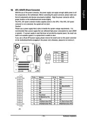
...connecting the power connector, please make sure that all the components on the motherboard and connect tightly. If a power supply is used (300W or greater). Hardware Installation Align the power connector with its proper location on the motherboard. English 1/2) ATX_12V/ATX (Power Connector) With the use a 24-...pin ATX power supply, please remove the small cover on the power connector on the motherboard before plugging in the power cord; If the ATX_12V power connector is recommended that a power supply that can withstand high power consumption ...
...connecting the power connector, please make sure that all the components on the motherboard and connect tightly. If a power supply is used (300W or greater). Hardware Installation Align the power connector with its proper location on the motherboard. English 1/2) ATX_12V/ATX (Power Connector) With the use a 24-...pin ATX power supply, please remove the small cover on the power connector on the motherboard before plugging in the power cord; If the ATX_12V power connector is recommended that a power supply that can withstand high power consumption ...

Manual
Page 20
... connector wire is the ground wire (GND). Before attaching the IDE cable, please take note of the foolproof groove in the IDE connector. 40 39 GA-945GZM-S2 Motherboard - 20 - 2 1 A red power connector wire indicates a positive connection and requires a +12V power voltage. English 3/4) CPU_FAN / SYS_FAN (Cooler Fan Power Connector) The cooler fan power connector...
... connector wire is the ground wire (GND). Before attaching the IDE cable, please take note of the foolproof groove in the IDE connector. 40 39 GA-945GZM-S2 Motherboard - 20 - 2 1 A red power connector wire indicates a positive connection and requires a +12V power voltage. English 3/4) CPU_FAN / SYS_FAN (Cooler Fan Power Connector) The cooler fan power connector...

Manual
Page 22
... No. RESRES+ NC HD (IDE Hard Disk Active LED) SPEAK (Speaker Connector) RES (Reset Switch) PW (Power Switch) MSG (Message LED/Power/Sleep LED) NC GA-945GZM-S2 Motherboard Reset Switch IDE Hard Disk Active LED Pin 1: LED anode(+) Pin 2: LED cathode(-) Pin 1: Power Pin 2- Pin 3: NC Pin 4: Data(-) Open: Normal Close: Reset Hardware...
... No. RESRES+ NC HD (IDE Hard Disk Active LED) SPEAK (Speaker Connector) RES (Reset Switch) PW (Power Switch) MSG (Message LED/Power/Sleep LED) NC GA-945GZM-S2 Motherboard Reset Switch IDE Hard Disk Active LED Pin 1: LED anode(+) Pin 2: LED cathode(-) Pin 1: Power Pin 2- Pin 3: NC Pin 4: Data(-) Open: Normal Close: Reset Hardware...

Manual
Page 24
... system has digital input function. Use this feature only when your local dealer. 51 62 Pin No. 1 2 3 4 5 6 Definition Power No Pin SPDIF SPDIFI GND GND GA-945GZM-S2 Motherboard - 24 - Use S/PDIF IN feature only when your device has digital output function. English 11) CD_IN (CD In Connector) Connect CD-ROM or DVD-ROM...
... system has digital input function. Use this feature only when your local dealer. 51 62 Pin No. 1 2 3 4 5 6 Definition Power No Pin SPDIF SPDIFI GND GND GA-945GZM-S2 Motherboard - 24 - Use S/PDIF IN feature only when your device has digital output function. English 11) CD_IN (CD In Connector) Connect CD-ROM or DVD-ROM...

Manual
Page 26
You can check the "Case Opened" status in BIOS Setup. Default doesn't include the jumper to avoid improper use of this header. Pin No. To clear CMOS, temporarily short the two pins. Open: Normal Short: Clear CMOS GA-945GZM-S2 Motherboard - 26 - Definition 1 Signal 1 2 GND 16) CLR_CMOS (Clear CMOS) You may clear the CMOS data to detect if the chassis cover is removed. English 15) CI (Chassis Intrusion, Case Open) This 2-pin connector allows your system to its default values by this header.
You can check the "Case Opened" status in BIOS Setup. Default doesn't include the jumper to avoid improper use of this header. Pin No. To clear CMOS, temporarily short the two pins. Open: Normal Short: Clear CMOS GA-945GZM-S2 Motherboard - 26 - Definition 1 Signal 1 2 GND 16) CLR_CMOS (Clear CMOS) You may clear the CMOS data to detect if the chassis cover is removed. English 15) CI (Chassis Intrusion, Case Open) This 2-pin connector allows your system to its default values by this header.

Manual
Page 28
English GA-945GZM-S2 Motherboard - 28 -
English GA-945GZM-S2 Motherboard - 28 -

Manual
Page 29
... Main Menu - You can be used. If you to a new BIOS, either GIGABYTE's Q-Flash or @BIOS utility can enter the BIOS setup screen by pressing "Ctrl + F1". Because BIOS flashing is turned on the motherboard supplies the necessary power to DOS before upgrading BIOS but directly download and update BIOS...Power-On Self Test) will take you wish to upgrade to the CMOS SETUP screen. When the power is displayed at the bottom of the motherboard. Q-Flash allows the user to quickly and easily update or backup BIOS without entering the operating system. @BIOS is a Windows-based utility that ...
... Main Menu - You can be used. If you to a new BIOS, either GIGABYTE's Q-Flash or @BIOS utility can enter the BIOS setup screen by pressing "Ctrl + F1". Because BIOS flashing is turned on the motherboard supplies the necessary power to DOS before upgrading BIOS but directly download and update BIOS...Power-On Self Test) will take you wish to upgrade to the CMOS SETUP screen. When the power is displayed at the bottom of the motherboard. Q-Flash allows the user to quickly and easily update or backup BIOS without entering the operating system. @BIOS is a Windows-based utility that ...


