Manual
Page 4
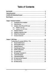
...GA-965G-DS3 Motherboard Layout 7 Block Diagram ...8 Chapter 1 Hardware Installation 9 1-1 Considerations Prior to Installation 9 1-2 Feature Summary 10 1-3 Installation of the CPU and CPU Cooler 12 1-3-1 Installation of the CPU 12 1-3-2 Installation of the CPU Cooler 13 1-4 Installation of Memory 14 1-5 Installation of Expansion Cards 16 1-6 I/O Back Panel Introduction 17 1-7 Connectors Introduction 18 Chapter 2 BIOS... Setup 29 The Main Menu (For example: BIOS Ver. : F7a 30 2-1 Standard CMOS Features 32 2-2 Advanced BIOS Features 34 2-3 ...
...GA-965G-DS3 Motherboard Layout 7 Block Diagram ...8 Chapter 1 Hardware Installation 9 1-1 Considerations Prior to Installation 9 1-2 Feature Summary 10 1-3 Installation of the CPU and CPU Cooler 12 1-3-1 Installation of the CPU 12 1-3-2 Installation of the CPU Cooler 13 1-4 Installation of Memory 14 1-5 Installation of Expansion Cards 16 1-6 I/O Back Panel Introduction 17 1-7 Connectors Introduction 18 Chapter 2 BIOS... Setup 29 The Main Menu (For example: BIOS Ver. : F7a 30 2-1 Standard CMOS Features 32 2-2 Advanced BIOS Features 34 2-3 ...

Manual
Page 5
Channel Audio Function Introduction 75 4-2 Troubleshooting 80 - 5 - Chapter 3 Install Drivers 51 3-1 Install Chipset Drivers 51 3-2 SoftwareApplications 52 3-3 Driver CD Information 52 3-4 Hardware Information 53 3-5 Contact Us ...53 Chapter 4 Appendix 55 4-1 Unique Software Utilities 55 4-1-1 EasyTune 5 Introduction 55 4-1-2 Xpress Recovery2 Introduction 56 4-1-3 Flash BIOS Method Introduction 58 4-1-4 Configuring SATA Hard Drive(s) (Controller: GIGABYTE SATA2 62 4-1-5 2- / 4- / 6- / 8-
Channel Audio Function Introduction 75 4-2 Troubleshooting 80 - 5 - Chapter 3 Install Drivers 51 3-1 Install Chipset Drivers 51 3-2 SoftwareApplications 52 3-3 Driver CD Information 52 3-4 Hardware Information 53 3-5 Contact Us ...53 Chapter 4 Appendix 55 4-1 Unique Software Utilities 55 4-1-1 EasyTune 5 Introduction 55 4-1-2 Xpress Recovery2 Introduction 56 4-1-3 Flash BIOS Method Introduction 58 4-1-4 Configuring SATA Hard Drive(s) (Controller: GIGABYTE SATA2 62 4-1-5 2- / 4- / 6- / 8-
Manual
Page 7
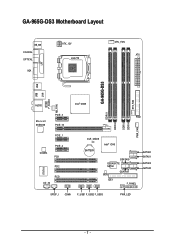
GA-965G-DS3 Motherboard Layout KB_MS COAXIAL OPTICAL VGA LPT ATX_12V LGA775 CPU_FAN ATX GA-965G-DS3 USB USB LAN SYS_FAN F_AUDIO AUDIO Intel® G965 NB_FAN DDRII1 PCIE_3 FDD Marvell 88E8056 PCIE_16 DDRII3 DDRII4 PWR_FAN DDRII2 PCIE_1 CODEC PCIE_2 PCI1 PCI2 IT8718 PCI3 CD_IN CLR_CMOS BATTERY Intel® ICH8 GSATAII0 GIGABYTE SATA2 GSATAII1 BIOS IDE1 CI F_PANEL SATAII0 SATAII1 SATAII2 SATAII3 SPDIF_I COMA F_USB1 F_USB2 F_USB3 PWR_LED - 7 -
GA-965G-DS3 Motherboard Layout KB_MS COAXIAL OPTICAL VGA LPT ATX_12V LGA775 CPU_FAN ATX GA-965G-DS3 USB USB LAN SYS_FAN F_AUDIO AUDIO Intel® G965 NB_FAN DDRII1 PCIE_3 FDD Marvell 88E8056 PCIE_16 DDRII3 DDRII4 PWR_FAN DDRII2 PCIE_1 CODEC PCIE_2 PCI1 PCI2 IT8718 PCI3 CD_IN CLR_CMOS BATTERY Intel® ICH8 GSATAII0 GIGABYTE SATA2 GSATAII1 BIOS IDE1 CI F_PANEL SATAII0 SATAII1 SATAII2 SATAII3 SPDIF_I COMA F_USB1 F_USB2 F_USB3 PWR_LED - 7 -
Manual
Page 8
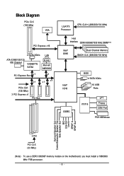
Block Diagram PCIe CLK (100 MHz) VGA PCI Express x16 ATA-33/66/100/133 IDE Channel 2 SATA 3Gb/s GIGABYTE SATA2 LAN RJ45 Marvell 88E8056 PCI Express Bus x 1 x1 x1 x1 x1 PCIe CLK (100 MHz) 3 PCI Express x1 PCI Bus LGA775 Processor CPU CLK+/-(...) Host Interface DDRII 800/667/533 MHz DIMM(Note) Intel® G965 Dual Channel Memory GMCH CLK (266/200/133 MHz) Intel® ICH8 CODEC BIOS 4 SATA 3Gb/s 10 USB Ports IT8718 LPT Floppy COM Port PS/2 KB/Mouse Surround Speaker Out Center/Subwoofer Speaker Out Side Speaker Out MIC Line...
Block Diagram PCIe CLK (100 MHz) VGA PCI Express x16 ATA-33/66/100/133 IDE Channel 2 SATA 3Gb/s GIGABYTE SATA2 LAN RJ45 Marvell 88E8056 PCI Express Bus x 1 x1 x1 x1 x1 PCIe CLK (100 MHz) 3 PCI Express x1 PCI Bus LGA775 Processor CPU CLK+/-(...) Host Interface DDRII 800/667/533 MHz DIMM(Note) Intel® G965 Dual Channel Memory GMCH CLK (266/200/133 MHz) Intel® ICH8 CODEC BIOS 4 SATA 3Gb/s 10 USB Ports IT8718 LPT Floppy COM Port PS/2 KB/Mouse Surround Speaker Out Center/Subwoofer Speaker Out Side Speaker Out MIC Line...
Manual
Page 11
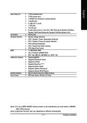
... Š CPU / System fan failure warning Š CPU Smart Fan Control BIOS Š 1 8 Mbit flash ROM Š Use of licensed AWARD BIOS Š PnP 1.0a, DMI 2.0, SM BIOS 2.3, ACPI 1.0b Additional Features Š Supports @BIOS Š Supports Download Center Š Supports Q-Flash Š Supports EasyTune ...(Note 2) Š Supports Xpress Install Š Supports Xpress Recovery2 Š Supports Xpress BIOS Rescue Bundle Software Š Norton Internet Security (OEM revision) Form Factor Š ATX form factor; 30.5cm x 21.0cm (Note...
... Š CPU / System fan failure warning Š CPU Smart Fan Control BIOS Š 1 8 Mbit flash ROM Š Use of licensed AWARD BIOS Š PnP 1.0a, DMI 2.0, SM BIOS 2.3, ACPI 1.0b Additional Features Š Supports @BIOS Š Supports Download Center Š Supports Q-Flash Š Supports EasyTune ...(Note 2) Š Supports Xpress Install Š Supports Xpress Recovery2 Š Supports Xpress BIOS Rescue Bundle Software Š Norton Internet Security (OEM revision) Form Factor Š ATX form factor; 30.5cm x 21.0cm (Note...
Manual
Page 12
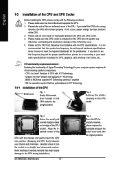
... the CPU Metal Lever Fig. 1 Gently lift the metal lever located on the CPU prior to the CPU during installation.) GA-965G-DS3 Motherboard - 12 - Please add an even layer of the CPU. BIOS: A BIOS that the motherboard supports the CPU. 2. Fig. 2 Remove the plastic covering on the edge of the CPU socket. Please take...
... the CPU Metal Lever Fig. 1 Gently lift the metal lever located on the CPU prior to the CPU during installation.) GA-965G-DS3 Motherboard - 12 - Please add an even layer of the CPU. BIOS: A BIOS that the motherboard supports the CPU. 2. Fig. 2 Remove the plastic covering on the edge of the CPU socket. Please take...
Manual
Page 14
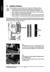
... switched off to insert the module, please switch the direction. The motherboard supports DDRII memory modules, whereby BIOS will automatically detect memory capacity and specifications. Insert the DIMM memory module vertically into the DIMM socket. GA-965G-DS3 Motherboard - 14 - Before installing or removing memory modules, please make sure that the computer power is...
... switched off to insert the module, please switch the direction. The motherboard supports DDRII memory modules, whereby BIOS will automatically detect memory capacity and specifications. Insert the DIMM memory module vertically into the DIMM socket. GA-965G-DS3 Motherboard - 14 - Before installing or removing memory modules, please make sure that the computer power is...
Manual
Page 16
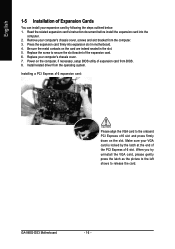
... to the left shows to the onboard PCI Express x16 slot and press firmly down on the computer, if necessary, setup BIOS utility of expansion card from the operating system. GA-965G-DS3 Motherboard - 16 - Remove your expansion card by the latch at the end of the PCI Express x16 slot. English 1-5 Installation of...
... to the left shows to the onboard PCI Express x16 slot and press firmly down on the computer, if necessary, setup BIOS utility of expansion card from the operating system. GA-965G-DS3 Motherboard - 16 - Remove your expansion card by the latch at the end of the PCI Express x16 slot. English 1-5 Installation of...
Manual
Page 22
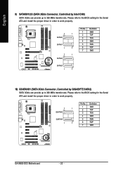
... install the proper driver in order to 300 MB/s transfer rate. English 9) SATAII0/1/2/3 (SATA 3Gb/s Connector, Controlled by GIGABYTE SATA2) SATA 3Gb/s can provide up to 300 MB/s transfer rate. Please refer to the BIOS setting for the Serial ATA and install the proper driver in order to work properly. 7 1 SATAII0 SATAII1.../s Connector, Controlled by Intel ICH8) SATA 3Gb/s can provide up to work properly. 7 1 GSATAII0 GSATAII1 1 7 Pin No. 1 2 3 4 5 6 7 Definition GND TXP TXN GND RXN RXP GND GA-965G-DS3 Motherboard - 22 -
... install the proper driver in order to 300 MB/s transfer rate. English 9) SATAII0/1/2/3 (SATA 3Gb/s Connector, Controlled by GIGABYTE SATA2) SATA 3Gb/s can provide up to 300 MB/s transfer rate. Please refer to the BIOS setting for the Serial ATA and install the proper driver in order to work properly. 7 1 SATAII0 SATAII1.../s Connector, Controlled by Intel ICH8) SATA 3Gb/s can provide up to work properly. 7 1 GSATAII0 GSATAII1 1 7 Pin No. 1 2 3 4 5 6 7 Definition GND TXP TXN GND RXN RXP GND GA-965G-DS3 Motherboard - 22 -
Manual
Page 27
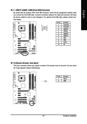
...) F_ USB1/F_USB2/F_USB3 (Front USB Connector) Be careful with the polarity of the front USB connector. You can check the "Case Opened" status in BIOS Setup. Hardware Installation Check the pin assignment carefully while you connect the front USB cable, incorrect connection between the cable and connector will make the...
...) F_ USB1/F_USB2/F_USB3 (Front USB Connector) Be careful with the polarity of the front USB connector. You can check the "Case Opened" status in BIOS Setup. Hardware Installation Check the pin assignment carefully while you connect the front USB cable, incorrect connection between the cable and connector will make the...
Manual
Page 29
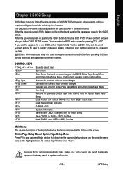
... Decrease the numeric value or make changes General help window that describes the appropriate keys to a new BIOS, either Gigabyte's Q-Flash or @BIOS utility can enter the BIOS setup screen by pressing "Ctrl + F1". English Chapter 2 BIOS Setup BIOS (Basic Input and Output System) includes a CMOS SETUP utility which allows user to configure required settings or...
... Decrease the numeric value or make changes General help window that describes the appropriate keys to a new BIOS, either Gigabyte's Q-Flash or @BIOS utility can enter the BIOS setup screen by pressing "Ctrl + F1". English Chapter 2 BIOS Setup BIOS (Basic Input and Output System) includes a CMOS SETUP utility which allows user to configure required settings or...
Manual
Page 30
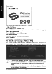
...select among the items and press to BIOS F12: Load CMOS from the exact settings for stability. 3. This action makes the system reset to the default settings for your motherboard. GA-965G-DS3 Motherboard - 30 - Startup Screen: English :POST Screen :BIOS Setup/Q-Flash :XpressRecovery2 :Boot Menu ...: POST Screen Press the TAB key to see BIOS POST screen. (To show the BIOS POST screen at system startup, refer to ...
...select among the items and press to BIOS F12: Load CMOS from the exact settings for stability. 3. This action makes the system reset to the default settings for your motherboard. GA-965G-DS3 Motherboard - 30 - Startup Screen: English :POST Screen :BIOS Setup/Q-Flash :XpressRecovery2 :Boot Menu ...: POST Screen Press the TAB key to see BIOS POST screen. (To show the BIOS POST screen at system startup, refer to ...
Manual
Page 31
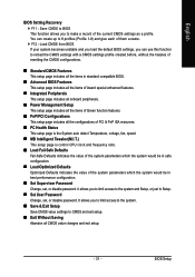
... It allows you can create up to 8 profiles (Profile 1-8) and give each of them a name. English BIOS Setting Recovery F11 : Save CMOS to BIOS This function allows you to limit access to the system. „ Save & Exit Setup Save CMOS value settings to CMOS and ...or disable password. You can use this function to make a record of the system parameters which the system would be in standard compatible BIOS. „ Advanced BIOS Features This setup page includes all the items of Award special enhanced features. „ Integrated Peripherals This setup page includes all onboard peripherals...
... It allows you can create up to 8 profiles (Profile 1-8) and give each of them a name. English BIOS Setting Recovery F11 : Save CMOS to BIOS This function allows you to limit access to the system. „ Save & Exit Setup Save CMOS value settings to CMOS and ...or disable password. You can use this function to make a record of the system parameters which the system would be in standard compatible BIOS. „ Advanced BIOS Features This setup page includes all the items of Award special enhanced features. „ Integrated Peripherals This setup page includes all onboard peripherals...

Manual
Page 32
...Channel 2/3 Master, IDE Channel 4/5 Master, Slave IDE Auto-Detection Press "Enter" to select this to set the access mode for automatic device detection. GA-965G-DS3 Motherboard - 32 - Week Month The week, from 1999 through 2099 Time The times format in the month) Year The year, from Sun to automatically...POST(default) • None Select this option for the hard drive. User can use one of the two methods: • Auto Allows BIOS to 31 (or the maximum allowed in . The four options are used and the system will skip the automatic detection step and allow for...
...Channel 2/3 Master, IDE Channel 4/5 Master, Slave IDE Auto-Detection Press "Enter" to select this to set the access mode for automatic device detection. GA-965G-DS3 Motherboard - 32 - Week Month The week, from 1999 through 2099 Time The times format in the month) Year The year, from Sun to automatically...POST(default) • None Select this option for the hard drive. User can use one of the two methods: • Auto Allows BIOS to 31 (or the maximum allowed in . The four options are used and the system will skip the automatic detection step and allow for...
Manual
Page 33
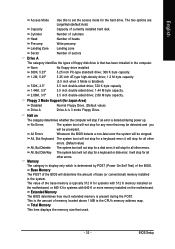
...it will stop for Japan Area) Disabled Drive A Normal Floppy Drive. (Default value) Drive A is determined by POST (Power On Self Test) of the BIOS. None No floppy drive installed 360K, 5.25" 5.25 inch PC-type standard drive; 360 K byte capacity. 1.2M, 5.25" 5.25 inch AT-type ... Disk/Key The system boot will not stop for systems with 512 K memory installed on the motherboard. BIOS Setup it will not stop for the hard drive. Extended Memory The BIOS determines how much extended memory is the amount of base (or conventional) memory installed in the computer. ...
...it will stop for Japan Area) Disabled Drive A Normal Floppy Drive. (Default value) Drive A is determined by POST (Power On Self Test) of the BIOS. None No floppy drive installed 360K, 5.25" 5.25 inch PC-type standard drive; 360 K byte capacity. 1.2M, 5.25" 5.25 inch AT-type ... Disk/Key The system boot will not stop for systems with 512 K memory installed on the motherboard. BIOS Setup it will not stop for the hard drive. Extended Memory The BIOS determines how much extended memory is the amount of base (or conventional) memory installed in the computer. ...
Manual
Page 34
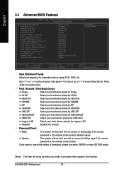
... Floppy. ZIP Select your boot device priority by ZIP. GA-965G-DS3 Motherboard - 34 - Capability CPU Hyper-Threading (Note) Limit CPUID Max. USB-FDD Select your boot device priority by USB-FDD. English 2-2 Advanced BIOS Features CMOS Setup Utility-Copyright (C) 1984-2006 Award Software Advanced BIOS Features Hard Disk Boot Priority First Boot Device Second...
... Floppy. ZIP Select your boot device priority by ZIP. GA-965G-DS3 Motherboard - 34 - Capability CPU Hyper-Threading (Note) Limit CPUID Max. USB-FDD Select your boot device priority by USB-FDD. English 2-2 Advanced BIOS Features CMOS Setup Utility-Copyright (C) 1984-2006 Award Software Advanced BIOS Features Hard Disk Boot Priority First Boot Device Second...
Manual
Page 35
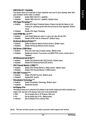
... (TM2) function. Please note that this feature is installed. to 3 (Note) Enabled Disabled Limit CPUID Maximum value to "Disabled". BIOS Setup Full Screen LOGO Show Enabled Show full screen logo at system startup. (Default value) Disabled Disable this function. Limit CPUID Max.... Enabled Enable HDD S.M.A.R.T. capability. If you wish to see BIOS POST screen, set this function. - 35 - PCI Onboard Set Init display first to PCI. (Default value) Set Init Display...
... (TM2) function. Please note that this feature is installed. to 3 (Note) Enabled Disabled Limit CPUID Maximum value to "Disabled". BIOS Setup Full Screen LOGO Show Enabled Show full screen logo at system startup. (Default value) Disabled Disable this function. Limit CPUID Max.... Enabled Enable HDD S.M.A.R.T. capability. If you wish to see BIOS POST screen, set this function. - 35 - PCI Onboard Set Init display first to PCI. (Default value) Set Init Display...
Manual
Page 37
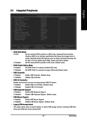
... ATA features such as Native Command Queuing and hot plug. Disabled Disable USB Keyboard Support. (Default value) USB Mouse Support Enabled Enable USB Mouse Support. BIOS Setup Enabled Enable USB 2.0 Controller. (Default value) Disabled Disable USB 2.0 Controller.
... ATA features such as Native Command Queuing and hot plug. Disabled Disable USB Keyboard Support. (Default value) USB Mouse Support Enabled Enable USB Mouse Support. BIOS Setup Enabled Enable USB 2.0 Controller. (Default value) Disabled Disable USB 2.0 Controller.
Manual
Page 38
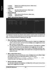
English Enabled Disabled Azalia Codec Auto Disabled BIOS will scan all four pairs of Pair 1-2 and Pair 3-6 will show Normal and the Length fields will show N/A. Refer to detect the status of wires, ... the Length fields show Short or Open and the length shown will detect cabling issue and report the approximate distance to the fault or short. GA-965G-DS3 Motherboard - 38 - When No LAN Cable Is Attached... If no LAN cable is detected on the LAN cable connected to the motherboard, the Status fields...
English Enabled Disabled Azalia Codec Auto Disabled BIOS will scan all four pairs of Pair 1-2 and Pair 3-6 will show Normal and the Length fields will show N/A. Refer to detect the status of wires, ... the Length fields show Short or Open and the length shown will detect cabling issue and report the approximate distance to the fault or short. GA-965G-DS3 Motherboard - 38 - When No LAN Cable Is Attached... If no LAN cable is detected on the LAN cable connected to the motherboard, the Status fields...
Manual
Page 39
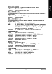
...Enable this function. (Default value) Onboard SATA/IDE Device This function allows users to enable or disable the SATA/IDE ports controlled by the GIGABYTE SATA2 controller. IDE Set the SATA channel to IDE mode.(Default value) AHCI Set the SATA channel to IDE mode. Enable onboard Serial port... 1 and address is 3E8/IRQ4. 2E8/IRQ3 Enable onboard Serial port 1 and address is 3BC/IRQ7. BIOS Setup For more details about AHCI, please visit Intel's website. Enable onboard LPT port and address is 2E8/IRQ3. Onboard Parallel Port Disabled 378...
...Enable this function. (Default value) Onboard SATA/IDE Device This function allows users to enable or disable the SATA/IDE ports controlled by the GIGABYTE SATA2 controller. IDE Set the SATA channel to IDE mode.(Default value) AHCI Set the SATA channel to IDE mode. Enable onboard Serial port... 1 and address is 3E8/IRQ4. 2E8/IRQ3 Enable onboard Serial port 1 and address is 3BC/IRQ7. BIOS Setup For more details about AHCI, please visit Intel's website. Enable onboard LPT port and address is 2E8/IRQ3. Onboard Parallel Port Disabled 378...


