
Manual
Page 1
GA-EP43-DS3LR/ GA-EP43-DS3L/ GA-EP43-S3L LGA775 socket motherboard for Intel® CoreTM processor family/ Intel® Pentium® processor family/Intel® Celeron® processor family User's Manual Rev. 1006 12ME-EP43DS3L-1006R
GA-EP43-DS3LR/ GA-EP43-DS3L/ GA-EP43-S3L LGA775 socket motherboard for Intel® CoreTM processor family/ Intel® Pentium® processor family/Intel® Celeron® processor family User's Manual Rev. 1006 12ME-EP43DS3L-1006R

Manual
Page 3
Motherboard GA-EP43-DS3LR Oct. 9, 2008 Motherboard GA-EP43-DS3LR Oct. 9, 2008
Motherboard GA-EP43-DS3LR Oct. 9, 2008 Motherboard GA-EP43-DS3LR Oct. 9, 2008

Manual
Page 5
Table of Contents Box Contents ...7 OptionalItems...7 GA-EP43-DS3LR/DS3L/S3L Motherboard Layout 8 Block Diagram...9 Chapter 1 Hardware Installation 11 1-1 Installation Precautions 11 1-2 Product Specifications 12 1-3 Installing the CPU and CPU Cooler 15 1-3-1 Installing the CPU 15 1-3-2 ...
Table of Contents Box Contents ...7 OptionalItems...7 GA-EP43-DS3LR/DS3L/S3L Motherboard Layout 8 Block Diagram...9 Chapter 1 Hardware Installation 11 1-1 Installation Precautions 11 1-2 Product Specifications 12 1-3 Installing the CPU and CPU Cooler 15 1-3-1 Installing the CPU 15 1-3-2 ...

Manual
Page 6
... (Optional 94 5-2-3 Configuring Microphone Recording 96 5-2-4 Using the Sound Recorder 98 5-3 Troubleshooting 99 5-3-1 Frequently Asked Questions 99 5-3-2 Troubleshooting Procedure 100 5-4 Regulatory Statements 102 Only for GA-EP43-DS3LR. - 6 -
... (Optional 94 5-2-3 Configuring Microphone Recording 96 5-2-4 Using the Sound Recorder 98 5-3 Troubleshooting 99 5-3-1 Frequently Asked Questions 99 5-3-2 Troubleshooting Procedure 100 5-4 Regulatory Statements 102 Only for GA-EP43-DS3LR. - 6 -

Manual
Page 7
... cable (Part No. 12CF1-1CM001-32R) LPT port cable (Part No. 12CF1-1LP001-01R) - 7 - The box contents are for reference only. Box Contents GA-EP43-DS3LR or GA-EP43-DS3L or GA-EP43-S3L motherboard Motherboard driver disk User's Manual Quick Installation Guide One IDE cable and one floppy disk drive cable Two SATA 3Gb/s cables I/O Shield •...
... cable (Part No. 12CF1-1CM001-32R) LPT port cable (Part No. 12CF1-1LP001-01R) - 7 - The box contents are for reference only. Box Contents GA-EP43-DS3LR or GA-EP43-DS3L or GA-EP43-S3L motherboard Motherboard driver disk User's Manual Quick Installation Guide One IDE cable and one floppy disk drive cable Two SATA 3Gb/s cables I/O Shield •...

Manual
Page 8
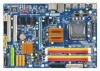
Only for GA-EP43-DS3L. Only for GA-EP43-DS3LR. - 8 - Only for GA-EP43-S3L. GA-EP43-DS3LR/DS3L/S3L Motherboard Layout KB_MS R_SPDIF COAXIAL R_USB_1 R_USB_2 R_USB_3 ATX_12V CPU_FAN PHASE LED ATX LGA775 DDR2_1 GA-EP43-DS3LR/DS3L/S3L DDR2_2 DDR2_3 DDR2_4 FDD SYS_FAN2 USB_LAN AUDIO Intel® P43 F_AUDIO SYS_FAN1 RTL8111C PCIEX1_1 PCIEX16 PCIEX1_2 PWR_FAN CODEC SPDIF_O ...ICH10 Intel® ICH10R SATA2_3 SATA2_0 SATA2_4 SATA2_ 1 JMicron 368 IDE SATA2_5 SATA2_2 F_USB1 F_PANEL PWR_LED COMA LPT F_USB2 "*" The GA-EP43-DS3LR/GA-EP43-DS3L adopts All-Solid Capacitor design.
Only for GA-EP43-DS3L. Only for GA-EP43-DS3LR. - 8 - Only for GA-EP43-S3L. GA-EP43-DS3LR/DS3L/S3L Motherboard Layout KB_MS R_SPDIF COAXIAL R_USB_1 R_USB_2 R_USB_3 ATX_12V CPU_FAN PHASE LED ATX LGA775 DDR2_1 GA-EP43-DS3LR/DS3L/S3L DDR2_2 DDR2_3 DDR2_4 FDD SYS_FAN2 USB_LAN AUDIO Intel® P43 F_AUDIO SYS_FAN1 RTL8111C PCIEX1_1 PCIEX16 PCIEX1_2 PWR_FAN CODEC SPDIF_O ...ICH10 Intel® ICH10R SATA2_3 SATA2_0 SATA2_4 SATA2_ 1 JMicron 368 IDE SATA2_5 SATA2_2 F_USB1 F_PANEL PWR_LED COMA LPT F_USB2 "*" The GA-EP43-DS3LR/GA-EP43-DS3L adopts All-Solid Capacitor design.

Manual
Page 9
... Speaker Out Center/Subwoofer Speaker Out Side Speaker Out MIC Line-Out Line-In SPDIF In SPDIF Out 2 PCI PCI CLK (33 MHz) Only for GA-EP43-S3L. Only for GA-EP43-DS3L. Only for GA-EP43-DS3LR. - 9 -
... Speaker Out Center/Subwoofer Speaker Out Side Speaker Out MIC Line-Out Line-In SPDIF In SPDIF Out 2 PCI PCI CLK (33 MHz) Only for GA-EP43-S3L. Only for GA-EP43-DS3L. Only for GA-EP43-DS3LR. - 9 -

Manual
Page 12
... of system memory (Note 1) Š Dual channel memory architecture Š Support for DDR2 1200/1066/800/667 MHz memory modules (Go to GIGABYTE's website for the latest memory support list.) Š Realtek ALC888 codec Š High Definition Audio Š 2/4/5.1/7.1-channel Š Support for S/... Up to 12 USB 2.0/1.1 ports (8 on the back panel, 4 via the USB brackets connected to 6 SATA 3Gb/s devices - Only for GA-EP43-DS3L. Only for GA-EP43-S3L. Support for GA-EP43-DS3LR. Only for SATA RAID 0, RAID 1, RAID 5 and RAID 10 Š JMicron 368 chip: - 1 x IDE connector supporting ATA-133...
... of system memory (Note 1) Š Dual channel memory architecture Š Support for DDR2 1200/1066/800/667 MHz memory modules (Go to GIGABYTE's website for the latest memory support list.) Š Realtek ALC888 codec Š High Definition Audio Š 2/4/5.1/7.1-channel Š Support for S/... Up to 12 USB 2.0/1.1 ports (8 on the back panel, 4 via the USB brackets connected to 6 SATA 3Gb/s devices - Only for GA-EP43-DS3L. Only for GA-EP43-S3L. Support for GA-EP43-DS3LR. Only for SATA RAID 0, RAID 1, RAID 5 and RAID 10 Š JMicron 368 chip: - 1 x IDE connector supporting ATA-133...

Manual
Page 13
Only for GA-EP43-DS3L. Internal Connectors Š 1 x 24-pin ATX main power connector Š 1 x 4-pin ATX 12V power connector Š 1 x floppy disk drive connector Š 1 x IDE connector Š 6 x .../System/Power fan speed detection Š CPU overheating warning Š CPU/System/Power fan fail warning Š CPU/System fan speed control (Note 2) Only for GA-EP43-DS3LR. - 13 - Hardware Installation
Only for GA-EP43-DS3L. Internal Connectors Š 1 x 24-pin ATX main power connector Š 1 x 4-pin ATX 12V power connector Š 1 x floppy disk drive connector Š 1 x IDE connector Š 6 x .../System/Power fan speed detection Š CPU overheating warning Š CPU/System/Power fan fail warning Š CPU/System fan speed control (Note 2) Only for GA-EP43-DS3LR. - 13 - Hardware Installation

Manual
Page 14
GA-EP43-DS3LR/DS3L/S3L Motherboard - 14 - BIOS Unique Features Bundled Software Operating System Form Factor Š 2 x 8 Mbit flash Š Use of licensed AWARD BIOS Š Support for DualBIOSTM Š ...
GA-EP43-DS3LR/DS3L/S3L Motherboard - 14 - BIOS Unique Features Bundled Software Operating System Form Factor Š 2 x 8 Mbit flash Š Use of licensed AWARD BIOS Š Support for DualBIOSTM Š ...

Manual
Page 16
... cover from the power outlet to prevent damage to correctly install the CPU into position. CPU Socket Lever Step 1: Completely raise the CPU socket lever. B. GA-EP43-DS3LR/DS3L/S3L Motherboard - 16 - Align the CPU pin one marking (triangle) with the pin one corner of the CPU socket (or you may align the CPU...
... cover from the power outlet to prevent damage to correctly install the CPU into position. CPU Socket Lever Step 1: Completely raise the CPU socket lever. B. GA-EP43-DS3LR/DS3L/S3L Motherboard - 16 - Align the CPU pin one marking (triangle) with the pin one corner of the CPU socket (or you may align the CPU...

Manual
Page 18
...limitation, read the following guidelines before installing the memory in Dual Channel mode. 1. Dual Channel mode cannot be used . (Go to GIGABYTE's website for optimum performance. When memory modules of the same capacity, brand, speed, and chips be enabled if only one direction. ...brand, speed, and chips be installed in only one DDR2 memory module is operating in Flex Memory Mode will double the original memory bandwidth. GA-EP43-DS3LR/DS3L/S3L Motherboard - 18 - The four DDR2 memory sockets are installed, a message which says memory is installed. 2. DS/SS - - 1-4 ...
...limitation, read the following guidelines before installing the memory in Dual Channel mode. 1. Dual Channel mode cannot be used . (Go to GIGABYTE's website for optimum performance. When memory modules of the same capacity, brand, speed, and chips be enabled if only one direction. ...brand, speed, and chips be installed in only one DDR2 memory module is operating in Flex Memory Mode will double the original memory bandwidth. GA-EP43-DS3LR/DS3L/S3L Motherboard - 18 - The four DDR2 memory sockets are installed, a message which says memory is installed. 2. DS/SS - - 1-4 ...
Manual
Page 20
... outlet before you begin to install an expansion card: • Make sure the motherboard supports the expansion card. Align the card with your operating system. GA-EP43-DS3LR/DS3L/S3L Motherboard - 20 - Turn on the card until it is fully seated in the expansion slot. 1. Example: Installing and Removing a PCI Express x16 Graphics Card...
... outlet before you begin to install an expansion card: • Make sure the motherboard supports the expansion card. Align the card with your operating system. GA-EP43-DS3LR/DS3L/S3L Motherboard - 20 - Turn on the card until it is fully seated in the expansion slot. 1. Example: Installing and Removing a PCI Express x16 Graphics Card...

Manual
Page 21
... at up to connect a PS/2 keyboard. Only for USB devices such as an USB keyboard/mouse, USB printer, USB flash drive and etc. Only for GA-EP43-DS3L. 1-6 Back Panel Connectors PS/2 Keyboard and PS/2 Mouse Port Use the upper port (green) to connect a PS/2 mouse and the lower port (purple) to... supports the USB 2.0/1.1 specification. Do not rock it straight out from your audio system provides a coaxial digital audio in connector. Before using this port for GA-EP43-DS3LR. - 21 -
... at up to connect a PS/2 keyboard. Only for USB devices such as an USB keyboard/mouse, USB printer, USB flash drive and etc. Only for GA-EP43-DS3L. 1-6 Back Panel Connectors PS/2 Keyboard and PS/2 Mouse Port Use the upper port (green) to connect a PS/2 mouse and the lower port (purple) to... supports the USB 2.0/1.1 specification. Do not rock it straight out from your audio system provides a coaxial digital audio in connector. Before using this port for GA-EP43-DS3LR. - 21 -

Manual
Page 22
... Jack (Black) Use this jack. Microphones must be reconfigured to connect center/subwoofer speakers in jack. Line Out Jack (Green) The default line out jack. GA-EP43-DS3LR/DS3L/S3L Motherboard - 22 - Line In Jack (Blue) The default line in Chapter 5, "Configuring 2/4/5.1/7.1-Channel Audio." Mic In Jack (Pink) The default Mic in a 5.1/7.1-channel audio...
... Jack (Black) Use this jack. Microphones must be reconfigured to connect center/subwoofer speakers in jack. Line Out Jack (Green) The default line out jack. GA-EP43-DS3LR/DS3L/S3L Motherboard - 22 - Line In Jack (Blue) The default line in Chapter 5, "Configuring 2/4/5.1/7.1-Channel Audio." Mic In Jack (Pink) The default Mic in a 5.1/7.1-channel audio...

Manual
Page 24
... Definition 3.3V -12V GND PS_ON(soft On/Off) GND GND GND -5V +5V +5V +5V (Only for 2x12-pinATX) GND (Only for 2x12-pin ATX) GA-EP43-DS3LR/DS3L/S3L Motherboard - 24 - The power connector possesses a foolproof design. If the 12V power connector is not connected, the computer will not start. • To meet...
... Definition 3.3V -12V GND PS_ON(soft On/Off) GND GND GND -5V +5V +5V +5V (Only for 2x12-pinATX) GND (Only for 2x12-pin ATX) GA-EP43-DS3LR/DS3L/S3L Motherboard - 24 - The power connector possesses a foolproof design. If the 12V power connector is not connected, the computer will not start. • To meet...

Manual
Page 26
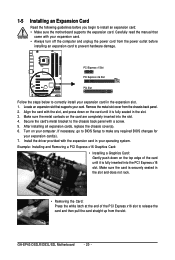
Only for GA-EP43-DS3L. If you wish to connect two IDE devices, remember to set the jumpers and the cabling according to the role of the SATA 3Gb/s ... supports a single SATA device. 7 SATA2_3 SATA2_4 SATA2_5 7 17 17 1 SATA2_0 SATA2_1 SATA2_2 1 Pin No. 1 2 3 4 5 6 7 Definition GND TXP TXN GND RXN RXP GND Only for GA-EP43-S3L. GA-EP43-DS3LR/DS3L/S3L Motherboard - 26 - Before attaching the IDE cable, locate the foolproof groove on the connector. 7) IDE (IDE Connector) The IDE connector supports up to SATA 3Gb...
Only for GA-EP43-DS3L. If you wish to connect two IDE devices, remember to set the jumpers and the cabling according to the role of the SATA 3Gb/s ... supports a single SATA device. 7 SATA2_3 SATA2_4 SATA2_5 7 17 17 1 SATA2_0 SATA2_1 SATA2_2 1 Pin No. 1 2 3 4 5 6 7 Definition GND TXP TXN GND RXN RXP GND Only for GA-EP43-S3L. GA-EP43-DS3LR/DS3L/S3L Motherboard - 26 - Before attaching the IDE cable, locate the foolproof groove on the connector. 7) IDE (IDE Connector) The IDE connector supports up to SATA 3Gb...
Manual
Page 27
... at least two hard drives. The LED keeps blinking when the system is in S1 sleep state. Refer to Chapter 5, "Configuring SATA Hard Drive(s)," for GA-EP43-DS3LR. - 27 - Definition 1 MPD+ 1 2 MPD- 3 MPD- If more than two hard drives are compatible with SATA 1.5Gb/s standard. The LED is operating. System Status LED S0...
... at least two hard drives. The LED keeps blinking when the system is in S1 sleep state. Refer to Chapter 5, "Configuring SATA Hard Drive(s)," for GA-EP43-DS3LR. - 27 - Definition 1 MPD+ 1 2 MPD- 3 MPD- If more than two hard drives are compatible with SATA 1.5Gb/s standard. The LED is operating. System Status LED S0...

Manual
Page 28
... module to Chapter 5, "Configuring 2/4/5.1/7.1-Channel Audio." • Some chassis provide a front panel audio module that has different wire assignments, please contact the chassis manufacturer. GA-EP43-DS3LR/DS3L/S3L Motherboard - 28 - For HD Front Panel Audio: For AC'97 Front Panel Audio: Pin No. If you want to mute the back panel audio (only...
... module to Chapter 5, "Configuring 2/4/5.1/7.1-Channel Audio." • Some chassis provide a front panel audio module that has different wire assignments, please contact the chassis manufacturer. GA-EP43-DS3LR/DS3L/S3L Motherboard - 28 - For HD Front Panel Audio: For AC'97 Front Panel Audio: Pin No. If you want to mute the back panel audio (only...
Manual
Page 30
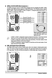
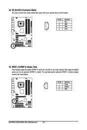
12) CD_IN (CD In Connector, Black) You may connect the audio cable that came with your optical drive to an audio device that supports digital audio out via an optional S/PDIF in cable, please contact the local dealer. 1 Pin No. Definition 1 Power 2 SPDIFI 3 GND GA-EP43-DS3LR/DS3L/S3L Motherboard - 30 - For purchasing the optional S/PDIF in cable. Definition 1 CD-L 2 GND 3 GND 4 CD-R 1 13) SPDIF_I (S/PDIF In Header, Red) This header supports digital S/PDIF in and can connect to the header. Pin No.
12) CD_IN (CD In Connector, Black) You may connect the audio cable that came with your optical drive to an audio device that supports digital audio out via an optional S/PDIF in cable, please contact the local dealer. 1 Pin No. Definition 1 Power 2 SPDIFI 3 GND GA-EP43-DS3LR/DS3L/S3L Motherboard - 30 - For purchasing the optional S/PDIF in cable. Definition 1 CD-L 2 GND 3 GND 4 CD-R 1 13) SPDIF_I (S/PDIF In Header, Red) This header supports digital S/PDIF in and can connect to the header. Pin No.