Manual
Page 4
... CPU Cooler 15 1-4 Installing the Memory 16 1-4-1 Dual/3 Channel Memory Configuration 16 1-4-2 Installing a Memory 17 1-5 Installing an Expansion Card 18 1-6 Installing the SATA Bracket 19 1-7 Back Panel Connectors 20 1-8 Internal Connectors 22 Chapter 2 BIOS Setup 35 2-1 Startup Screen 36 2-2 The Main Menu 37 2-3 MB Intelligent Tweaker(M.I.T 39 2-4 Standard CMOS Features 49 2-5 Advanced BIOS Features 51 2-6 Integrated Peripherals 53 2-7 Power Management Setup 56 2-8 PC Health Status 58 2-9 Load Fail-Safe Defaults 60 2-10 Load Optimized Defaults 60 2-11 Set Supervisor/User...
... CPU Cooler 15 1-4 Installing the Memory 16 1-4-1 Dual/3 Channel Memory Configuration 16 1-4-2 Installing a Memory 17 1-5 Installing an Expansion Card 18 1-6 Installing the SATA Bracket 19 1-7 Back Panel Connectors 20 1-8 Internal Connectors 22 Chapter 2 BIOS Setup 35 2-1 Startup Screen 36 2-2 The Main Menu 37 2-3 MB Intelligent Tweaker(M.I.T 39 2-4 Standard CMOS Features 49 2-5 Advanced BIOS Features 51 2-6 Integrated Peripherals 53 2-7 Power Management Setup 56 2-8 PC Health Status 58 2-9 Load Fail-Safe Defaults 60 2-10 Load Optimized Defaults 60 2-11 Set Supervisor/User...
Manual
Page 10
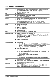
... to PCI Express 2.0 standard.) 1 x PCI Express x4 slot 1 x PCI Express x1 slot 3 x PCI slots South Bridge: - 6 x SATA 3Gb/s connectors (SATA2_0, SATA2_1, SATA2_2, SATA2_3, SATA2_4, SATA2_5) supporting up to 2 SATA 3Gb/s devices - 1-2 Product Specifications CPU QPI Chipset Memory Audio LAN Expansion Slots Storage Interface USB IEEE 1394 Support for an Intel® CoreTM i7 series processor in the South Bridge Up to 12 USB 2.0/1.1 ports (8 on the back panel, 1 via the USB brackets connected to the internal USB headers) ...
... to PCI Express 2.0 standard.) 1 x PCI Express x4 slot 1 x PCI Express x1 slot 3 x PCI slots South Bridge: - 6 x SATA 3Gb/s connectors (SATA2_0, SATA2_1, SATA2_2, SATA2_3, SATA2_4, SATA2_5) supporting up to 2 SATA 3Gb/s devices - 1-2 Product Specifications CPU QPI Chipset Memory Audio LAN Expansion Slots Storage Interface USB IEEE 1394 Support for an Intel® CoreTM i7 series processor in the South Bridge Up to 12 USB 2.0/1.1 ports (8 on the back panel, 1 via the USB brackets connected to the internal USB headers) ...
Manual
Page 16
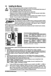
... enabling Dual Channel mode with two memory modules, be installed in Flex Memory Mode will automatically detect the specifications and capacity of the same capacity, brand, speed, and chips be sure to prevent hardware damage. • Memory modules have a foolproof design. A memory module can be sure to insert the memory, switch the direction. 1-4-1 Dual/3 Channel Memory Configuration This motherboard provides six DDR3 memory sockets and supports Dual/3 Channel Technology. Intel ® Flex Memory Technology offers greater flexibility to upgrade...
... enabling Dual Channel mode with two memory modules, be installed in Flex Memory Mode will automatically detect the specifications and capacity of the same capacity, brand, speed, and chips be sure to prevent hardware damage. • Memory modules have a foolproof design. A memory module can be sure to insert the memory, switch the direction. 1-4-1 Dual/3 Channel Memory Configuration This motherboard provides six DDR3 memory sockets and supports Dual/3 Channel Technology. Intel ® Flex Memory Technology offers greater flexibility to upgrade...
Manual
Page 24
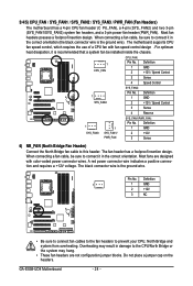
... wire). When connecting a fan cable, be installed inside the chassis. 1 CPU_FAN 1 SYS_FAN2 1 SYS_FAN3 1 SYS_FAN1/ PWR_FAN CPU_FAN: Pin No. For optimum heat dissipation, it is the ground wire. Most fans are not configuration jumper blocks. Definition 1 1 GND 2 +12V 3 NC • Be sure to connect fan cables to the fan headers to this header. Most fan headers possess a foolproof insertion design. The motherboard supports CPU fan speed control, which requires the use of a CPU fan with color-coded power connector wires. Definition 1 GND 2 +12V / Speed Control...
... wire). When connecting a fan cable, be installed inside the chassis. 1 CPU_FAN 1 SYS_FAN2 1 SYS_FAN3 1 SYS_FAN1/ PWR_FAN CPU_FAN: Pin No. For optimum heat dissipation, it is the ground wire. Most fans are not configuration jumper blocks. Definition 1 1 GND 2 +12V 3 NC • Be sure to connect fan cables to the fan headers to this header. Most fan headers possess a foolproof insertion design. The motherboard supports CPU fan speed control, which requires the use of a CPU fan with color-coded power connector wires. Definition 1 GND 2 +12V / Speed Control...
Manual
Page 33
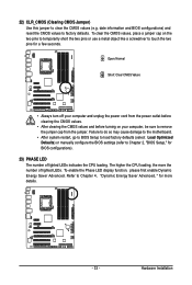
... (Clearing CMOS Jumper) Use this jumper to factory defaults. Failure to do so may cause damage to the motherboard. • After system restart, go to BIOS Setup to load factory defaults (select Load Optimized Defaults) or manually configure the BIOS settings (refer to touch the two pins for BIOS configurations). 23) PHASE LED The number of lighted LEDs. To enable the Phase LED display function, please first enable Dynamic Energy Saver Advanced. Hardware Installation date information and BIOS configurations) and reset the CMOS...
... (Clearing CMOS Jumper) Use this jumper to factory defaults. Failure to do so may cause damage to the motherboard. • After system restart, go to BIOS Setup to load factory defaults (select Load Optimized Defaults) or manually configure the BIOS settings (refer to touch the two pins for BIOS configurations). 23) PHASE LED The number of lighted LEDs. To enable the Phase LED display function, please first enable Dynamic Energy Saver Advanced. Hardware Installation date information and BIOS configurations) and reset the CMOS...
Manual
Page 38
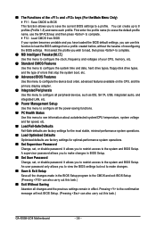
First enter the profile name (to erase the default profile name, use this function to load the BIOS settings from BIOS If your CPU, memory, etc. Standard CMOS Features Use this menu to configure the system time and date, hard drive types, floppy disk drive types, and the type of reconfiguring the BIOS settings. A supervisor password allows you to make changes. Save & Exit Setup Save all changes and the previous settings remain in BIOS Setup. Set User Password Change, set , or disable password. It allows...
First enter the profile name (to erase the default profile name, use this function to load the BIOS settings from BIOS If your CPU, memory, etc. Standard CMOS Features Use this menu to configure the system time and date, hard drive types, floppy disk drive types, and the type of reconfiguring the BIOS settings. A supervisor password allows you to make changes. Save & Exit Setup Save all changes and the previous settings remain in BIOS Setup. Set User Password Change, set , or disable password. It allows...
Manual
Page 39
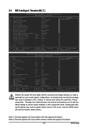
... CMOS values and reset the board to CPU, chipset, or memory and reduce the useful life of these components. BIOS Setup 2-3 MB Intelligent Tweaker(M.I.T.) CMOS Setup Utility-Copyright (C) 1984-2008 Award Software MB Intelligent Tweaker(M.I.T.) CPU Clock Ratio (Note 1) CPU Frequency Advanced CPU Features QPI Link Speed QPI Link Speed UnCore & QPI Features Base Clock(BCLK) Control x BCLK Frequency (Mhz) Advanced Clock Control Performance Enhance Extreme Memory Profile (X.M.P.) (Note 2) System Memory Multiplier (SPD) Memory Frequency (Mhz) 800 DRAM...
... CMOS values and reset the board to CPU, chipset, or memory and reduce the useful life of these components. BIOS Setup 2-3 MB Intelligent Tweaker(M.I.T.) CMOS Setup Utility-Copyright (C) 1984-2008 Award Software MB Intelligent Tweaker(M.I.T.) CPU Clock Ratio (Note 1) CPU Frequency Advanced CPU Features QPI Link Speed QPI Link Speed UnCore & QPI Features Base Clock(BCLK) Control x BCLK Frequency (Mhz) Advanced Clock Control Performance Enhance Extreme Memory Profile (X.M.P.) (Note 2) System Memory Multiplier (SPD) Memory Frequency (Mhz) 800 DRAM...
Manual
Page 41
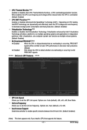
... Enter: Select F5: Previous Values +/-/PU/PD: Value F10: Save F6: Fail-Safe Defaults ESC: Exit F1: General Help F7: Optimized Defaults QPI Link Speed Allows you to set the UnCore frequency. CPU Thermal Monitor (Note) Enables or disables Intel CPU Thermal Monitor function, a CPU overheating protection function. Depending on CPU loading, Intel EIST technology can function as multiple virtual systems. (Default: Enabled) Bi-Directional PROCHOT (Note) Enabled Disabled When the CPU or chipset...
... Enter: Select F5: Previous Values +/-/PU/PD: Value F10: Save F6: Fail-Safe Defaults ESC: Exit F1: General Help F7: Optimized Defaults QPI Link Speed Allows you to set the UnCore frequency. CPU Thermal Monitor (Note) Enables or disables Intel CPU Thermal Monitor function, a CPU overheating protection function. Depending on CPU loading, Intel EIST technology can function as multiple virtual systems. (Default: Enabled) Bi-Directional PROCHOT (Note) Enabled Disabled When the CPU or chipset...
Manual
Page 42
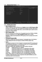
... CPU loading. Warning: Before using C.I .A.2. (Default) Cruise Increases CPU frequency by 7% or 9% depending on your system bus to 150 MHz. ******* Advanced Clock Control ******* CMOS Setup Utility-Copyright (C) 1984-2008 Award Software Advanced Clock Control >>>>> Sandard Clock Control Base Clock(BCLK) Control x BCLK Frequency (Mhz) PCI Express Frequency (Mhz) C.I .A.2) is designed to automatically adjust CPU computing power to maximize system performance. The adjustable range is enabled. Auto sets the PCIe clock frequency to standard 100 MHz. (Default: Auto) C.I.A.2 CPU...
... CPU loading. Warning: Before using C.I .A.2. (Default) Cruise Increases CPU frequency by 7% or 9% depending on your system bus to 150 MHz. ******* Advanced Clock Control ******* CMOS Setup Utility-Copyright (C) 1984-2008 Award Software Advanced Clock Control >>>>> Sandard Clock Control Base Clock(BCLK) Control x BCLK Frequency (Mhz) PCI Express Frequency (Mhz) C.I .A.2) is designed to automatically adjust CPU computing power to maximize system performance. The adjustable range is enabled. Auto sets the PCIe clock frequency to standard 100 MHz. (Default: Auto) C.I.A.2 CPU...
Manual
Page 47
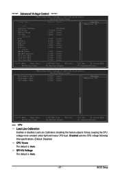
...BIOS Setup Disabled sets the CPU voltage following Intel specifications. (Default: Disabled) CPU Vcore The default is Auto. - 47 - ******* Advanced Voltage Control ******* CMOS Setup Utility-Copyright (C) 1984-2008 Award Software Advanced Voltage Control Voltage Types Normal Current >>> CPU Load-Line Calibration [Disabled] CPU Vcore 1.22500V [Auto] QPI/Vtt Voltage 1.150V [Auto] CPU PLL 1.800V [Auto] >>> MCH/ICH PCIE 1.500V [Auto] QPI PLL 1.100V [Auto] IOH Core 1.100V [Auto ICH I/O 1.500V [Auto] ICH Core 1.100V [Auto] >>> DRAM DRAM Voltage 1.500V [Auto] DRAM...
...BIOS Setup Disabled sets the CPU voltage following Intel specifications. (Default: Disabled) CPU Vcore The default is Auto. - 47 - ******* Advanced Voltage Control ******* CMOS Setup Utility-Copyright (C) 1984-2008 Award Software Advanced Voltage Control Voltage Types Normal Current >>> CPU Load-Line Calibration [Disabled] CPU Vcore 1.22500V [Auto] QPI/Vtt Voltage 1.150V [Auto] CPU PLL 1.800V [Auto] >>> MCH/ICH PCIE 1.500V [Auto] QPI PLL 1.100V [Auto] IOH Core 1.100V [Auto ICH I/O 1.500V [Auto] ICH Core 1.100V [Auto] >>> DRAM DRAM Voltage 1.500V [Auto] DRAM...
Manual
Page 51
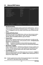
... CMOS Setup Utility-Copyright (C) 1984-2008 Award Software Advanced BIOS Features Hard Disk Boot Priority First Boot Device [Press Enter] [Floppy] Item Help Menu Level Second Boot Device Third Boot Device Password Check [Hard Disk] [CDROM] [Setup] HDD S.M.A.R.T. Options are: Floppy, LS120, Hard Disk, CDROM, ZIP, USB-FDD, USB-ZIP, USB-CDROM, USB-HDD, Legacy LAN, Disabled. After configuring this item to issue warnings when a third party hardware monitor utility is installed. (Default: Disabled) Limit CPUID Max. Use the up or down arrow key to select a hard drive...
... CMOS Setup Utility-Copyright (C) 1984-2008 Award Software Advanced BIOS Features Hard Disk Boot Priority First Boot Device [Press Enter] [Floppy] Item Help Menu Level Second Boot Device Third Boot Device Password Check [Hard Disk] [CDROM] [Setup] HDD S.M.A.R.T. Options are: Floppy, LS120, Hard Disk, CDROM, ZIP, USB-FDD, USB-ZIP, USB-CDROM, USB-HDD, Legacy LAN, Disabled. After configuring this item to issue warnings when a third party hardware monitor utility is installed. (Default: Disabled) Limit CPUID Max. Use the up or down arrow key to select a hard drive...
Manual
Page 52
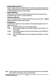
... For HDD (Secs) Allows you install a CPU that supports this feature. PCI Sets the PCI graphics card as the first display. (Default) PEG Sets PCI Express graphics card on the first PCI Express x16 slot (PCIEX16_1) as the first display. For more information about Intel CPUs' unique features, please visit Intel's website. GA-EX58-UD4 Motherboard - 52 - PEG3 Sets PCI Express graphics card on the second PCI Express x16 slot (PCIEX16_2) as the first display. No-Execute Memory Protect (Note) Enables or disables Intel Execute Disable Bit function. Disabled displays...
... For HDD (Secs) Allows you install a CPU that supports this feature. PCI Sets the PCI graphics card as the first display. (Default) PEG Sets PCI Express graphics card on the first PCI Express x16 slot (PCIEX16_1) as the first display. For more information about Intel CPUs' unique features, please visit Intel's website. GA-EX58-UD4 Motherboard - 52 - PEG3 Sets PCI Express graphics card on the second PCI Express x16 slot (PCIEX16_2) as the first display. No-Execute Memory Protect (Note) Enables or disables Intel Execute Disable Bit function. Disabled displays...
Manual
Page 53
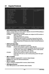
...Default) RAID Enables RAID for the SATA controllers. USB 2.0 Controller Enables or disables the integrated USB 2.0 controller. (Default: Enabled) USB Keyboard Function Allows USB keyboard to AHCI mode. Enable Native IDE mode if you wish to install operating systems that support Native mode. SATA Port0-3 Native Mode Specifies the operating mode of the USB functionalities below. Set this option to Disabled if you wish to AHCI mode. 2-6 Integrated Peripherals CMOS Setup Utility-Copyright (C) 1984-2008 Award Software Integrated Peripherals SATA RAID/AHCI Mode SATA...
...Default) RAID Enables RAID for the SATA controllers. USB 2.0 Controller Enables or disables the integrated USB 2.0 controller. (Default: Enabled) USB Keyboard Function Allows USB keyboard to AHCI mode. Enable Native IDE mode if you wish to install operating systems that support Native mode. SATA Port0-3 Native Mode Specifies the operating mode of the USB functionalities below. Set this option to Disabled if you wish to AHCI mode. 2-6 Integrated Peripherals CMOS Setup Utility-Copyright (C) 1984-2008 Award Software Integrated Peripherals SATA RAID/AHCI Mode SATA...
Manual
Page 55
... Displays transmission speed Displays the approximate length of 10/100/1000 Mbps in MS-DOS mode; IDE Disables RAID for the SATA controller and configures the SATA controller to PATA mode. (Default) AHCI Configures the SATA controller to enable advanced Serial ATA features such as Native Command Queuing and hot plug. Advanced Host Controller Interface (AHCI) is the approximate length of 10/100 Mbps in Windows mode or when the LAN Boot ROM is detected on the LAN cable connected to AHCI mode...
... Displays transmission speed Displays the approximate length of 10/100/1000 Mbps in MS-DOS mode; IDE Disables RAID for the SATA controller and configures the SATA controller to PATA mode. (Default) AHCI Configures the SATA controller to enable advanced Serial ATA features such as Native Command Queuing and hot plug. Advanced Host Controller Interface (AHCI) is the approximate length of 10/100 Mbps in Windows mode or when the LAN Boot ROM is detected on the LAN cable connected to AHCI mode...
Manual
Page 59
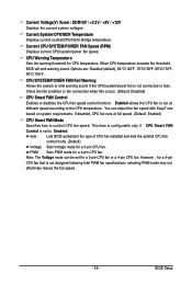
... System/CPU/MCH Temperature Displays current system/CPU/North Bridge temperature. Options are: Disabled (default), 60 oC/140oF, 70oC/158oF, 80oC/176oF, 90oC/194oF. CPU/SYSTEM/POWER FAN Fail Warning Allows the system to control CPU fan speed. Auto Lets BIOS autodetect the type of CPU fan installed and sets the optimal CPU fan control mode. (Default) Voltage Sets Voltage mode for a 3-pin CPU fan or a 4-pin CPU fan. Enabled allows the CPU fan to run at full speed. (Default: Enabled) CPU Smart FAN Mode Specifies how to emit warning sound if the CPU/system/power fan is not...
... System/CPU/MCH Temperature Displays current system/CPU/North Bridge temperature. Options are: Disabled (default), 60 oC/140oF, 70oC/158oF, 80oC/176oF, 90oC/194oF. CPU/SYSTEM/POWER FAN Fail Warning Allows the system to control CPU fan speed. Auto Lets BIOS autodetect the type of CPU fan installed and sets the optimal CPU fan control mode. (Default) Voltage Sets Voltage mode for a 3-pin CPU fan or a 4-pin CPU fan. Enabled allows the CPU fan to run at full speed. (Default: Enabled) CPU Smart FAN Mode Specifies how to emit warning sound if the CPU/system/power fan is not...

Manual
Page 74
... set . GA-EX58-UD4 Motherboard - 74 - Available functions in Quick Boost mode or clicking Default to restore to default values, be changed linearly based on the CPU temperature thresholds you set temperature/fan speed alarm.You can select memory module on a specific slot to be sure to restart your own sound file (.wav file). (Note) Due to the hardware limitation, you must install a DDR3 1066 MHz memory module(s) (or above) to change system clock settings and voltages settings using...
... set . GA-EX58-UD4 Motherboard - 74 - Available functions in Quick Boost mode or clicking Default to restore to default values, be changed linearly based on the CPU temperature thresholds you set temperature/fan speed alarm.You can select memory module on a specific slot to be sure to restart your own sound file (.wav file). (Note) Due to the hardware limitation, you must install a DDR3 1066 MHz memory module(s) (or above) to change system clock settings and voltages settings using...
Manual
Page 80
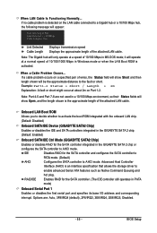
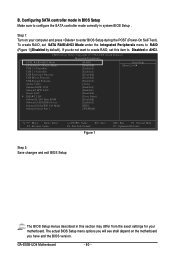
... BIOS version. The BIOS Setup menus described in BIOS Setup Make sure to RAID (Figure 1)(Disabled by default). CMOS Setup Utility-Copyright (C) 1984-2008 Award Software Integrated Peripherals SATA RAID/AHCI Mode SATA Port0-3 Native Mode USB 1.0 Controller USB 2.0 Controller USB Keyboard Function USB Mouse Function USB Storage Function Azalia Codec Onboard H/W 1394 Onboard H/W LAN Green LAN SMART LAN Onboard LAN1 Boot ROM Onboard SATA/IDE Device Onboard SATA/IDE Ctrl Mode Onboard Serial Port 1 [RAID] [Disabled] [Enabled] [Enabled] [Disabled] [Disabled] [Enabled] [Auto] [Enabled...
... BIOS version. The BIOS Setup menus described in BIOS Setup Make sure to RAID (Figure 1)(Disabled by default). CMOS Setup Utility-Copyright (C) 1984-2008 Award Software Integrated Peripherals SATA RAID/AHCI Mode SATA Port0-3 Native Mode USB 1.0 Controller USB 2.0 Controller USB Keyboard Function USB Mouse Function USB Storage Function Azalia Codec Onboard H/W 1394 Onboard H/W LAN Green LAN SMART LAN Onboard LAN1 Boot ROM Onboard SATA/IDE Device Onboard SATA/IDE Ctrl Mode Onboard Serial Port 1 [RAID] [Disabled] [Enabled] [Enabled] [Disabled] [Disabled] [Enabled] [Auto] [Enabled...
Manual
Page 85
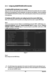
... the BIOS version. - 85 - B. Step 1: Turn on your power supply to IDE or AHCI, depending on the motherboard. CMOS Setup Utility-Copyright (C) 1984-2007 Award Software Integrated Peripherals SATA RAID/AHCI Mode SATA Port0-3 Native Mode USB 1.0 Controller USB 2.0 Controller USB Keyboard Function USB Mouse Function USB Storage Function Azalia Codec Onboard H/W 1394 Onboard H/W LAN Green LAN SMART LAN Onboard LAN1 Boot ROM Onboard SATA/IDE Device Onboard SATA/IDE Ctrl Mode Onboard Serial Port 1 [Disabled] [Disabled] [Enabled] [Enabled] [Disabled] [Disabled] [Enabled] [Auto] [Enabled...
... the BIOS version. - 85 - B. Step 1: Turn on your power supply to IDE or AHCI, depending on the motherboard. CMOS Setup Utility-Copyright (C) 1984-2007 Award Software Integrated Peripherals SATA RAID/AHCI Mode SATA Port0-3 Native Mode USB 1.0 Controller USB 2.0 Controller USB Keyboard Function USB Mouse Function USB Storage Function Azalia Codec Onboard H/W 1394 Onboard H/W LAN Green LAN SMART LAN Onboard LAN1 Boot ROM Onboard SATA/IDE Device Onboard SATA/IDE Ctrl Mode Onboard Serial Port 1 [Disabled] [Disabled] [Enabled] [Enabled] [Disabled] [Disabled] [Enabled] [Auto] [Enabled...
Manual
Page 86
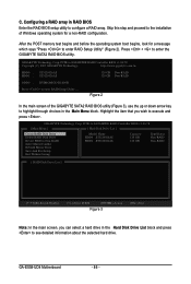
... Technology Corp. Configuring a RAID array in the Main Menu block. Figure 2 In the main screen of Windows operating system for a message which says "Press to configure a RAID array. Skip this step and proceed to the installation of the GIGABYTE SATA2 RAID BIOS utility (Figure 3), use the up or down arrow key to highlight through choices in RAID BIOS Enter the RAID BIOS setup utility to enter RAID Setup Utility" (Figure 2). C. PCIE-to-SATAII/IDE RAID Controller BIOS v1.06.78 [ Main Menu ] [ Hard Disk Drive List ] Create RAID Disk Drive Delete RAID Disk Drive Revert HDD...
... Technology Corp. Configuring a RAID array in the Main Menu block. Figure 2 In the main screen of Windows operating system for a message which says "Press to configure a RAID array. Skip this step and proceed to the installation of the GIGABYTE SATA2 RAID BIOS utility (Figure 3), use the up or down arrow key to highlight through choices in RAID BIOS Enter the RAID BIOS setup utility to enter RAID Setup Utility" (Figure 2). C. PCIE-to-SATAII/IDE RAID Controller BIOS v1.06.78 [ Main Menu ] [ Hard Disk Drive List ] Create RAID Disk Drive Delete RAID Disk Drive Revert HDD...
Manual
Page 93
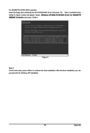
...use with the Windows XP installation. - 93 - Then a controller menu similar to continue the driver installation. Select the SCSI Adapter you can proceed with Windows, using a device support disk provided by an adapter manufacturer. After the driver installation, you want from the following list, or press ESC to return to the previous screen. (Windows XP/2003) RAID/AHCI Driver for GIGABYTE GBB36X Controller (Windows 2000) RAID Driver for GIGABYTE GBB363 Controller (Windows 2000) AHCI Driver for GIGABYTE GBB363 Controller (Windows 2000) RAID Driver for GIGABYTE GBB360 Controller ENTER...
...use with the Windows XP installation. - 93 - Then a controller menu similar to continue the driver installation. Select the SCSI Adapter you can proceed with Windows, using a device support disk provided by an adapter manufacturer. After the driver installation, you want from the following list, or press ESC to return to the previous screen. (Windows XP/2003) RAID/AHCI Driver for GIGABYTE GBB36X Controller (Windows 2000) RAID Driver for GIGABYTE GBB363 Controller (Windows 2000) AHCI Driver for GIGABYTE GBB363 Controller (Windows 2000) RAID Driver for GIGABYTE GBB360 Controller ENTER...


